de manincor FK600 Manual

englishespañol
USER AND MAINTENANCE HANDBOOK
Thermocookers and Thermostoves
INSTRUCCIONES DE USO Y MANTENIMIENTO
Termococinas y Termoestufas de leña

2

INDEX english
NORMAS DE SEGURIDAD 16
1. IDENTIFICACIÓN DEL APARATO 16
1.1 PLACA DE IDENTIFICACIÓN 16
1.2 TABLA DE DATOS TÉCNICOS 16
1.3
DESCRIPCIÓN TERMOCOCINAS SERIE CLASSICA 17
1.4
DESCRIPCIÓN TERMOCOCINAS SERIE ECO 17
1.5 DESCRIPCIÓN TERMOESTUFAS 17
2. INSTALLATION 18
2.1 MOVIMIENTO Y COLOCACIÓN 18
2.2 DISTANCIA DE SEGURIDAD 18
2.3 SERIE ECO: REGULACIÓN DEL BLOQUEO DE LA
DE LA PUERTA DE FUEGO 19
2.4 LA SALIDA DE HUMOS 19
CARACTERÍSTICAS DE LA SALIDA DE HUMOS 19
DIMENSIONES DE LA SALIDA DE HUMOS 19
CONEXIÓN AL CAÑÓN DE LA SALIDA DE HUMOS 20
2.5
CONEXIÓN HIDRÁULICA 20
CONEXIÓN A UNA INSTALACIÓN DE VASO CERRADO
21
CONEXIÓN A UNA INSTALACIÓN DE VASO ABIERTO
22
3. INSTRUCCIONES DE USO 23
EL COMBUSTIBLE 23
PRIMER ENCENDIDO 23
3.1 NORMAS DE USO 23
PUESTA EN FUNCIONAMIENTO 23
FUNCIONAMIENTO 24
VELOCIDAD DE LA COMBUSTIÓN 24
3.2 USO DEL HORNO 24
3.3 CONSEJOS ÚTILES 24
3.4 QUÉ HACER SI... 25
4. MANTENIMIENTO 26
4.1
LIMPIEZA ORDINARIA Y CONTROLES PERIÓDICOS 26
4.2 MANTENIMIENTO DE LA PLANCHA RADIANTE 26
4.3 PLACA Y OTRAS PARTES EXTERNAS 27
5. GARANTÍA 27
ÍNDICE español
SAFETY RULES 4
1. IDENTIFICATION OF THE APPLIANCE 4
1.1 IDENTIFICATION PLATE 4
1.2 TABLE OF TECHNICAL SPECIFICATIONS 4
1.3 D
ESCRIPTION OF THE CLASSICA THERMOCOOKER
5
1.4 DESCRIPTION OF THE ECO THERMOCOOKER 5
1.5 DESCRIPTION OF THE THERMOSTOVE 5
2. INSTALLATION 6
2.1 HANDLING AND INSTALLATION 6
2.2 SAFETY CLEARANCE 6
2.3 ECO SERIES: ADJUSTING THE FIREDOOR LOCK 7
2.4 THE FLUE SYSTEM 7
FLUE PIPE CHARACTERISTICS 7
FLUE PIPE DIMENSIONS 7
CONNECTION TO THE FLUE PIPE 8
2.5 HYDRAULIC CONNECTION 8
CONNECTION TO A CLOSED SYSTEM 9
CONNECTION TO AN OPEN-CUP SYSTEM 10
3. INSTRUCTIONS ON USE 11
FUEL 11
INITIAL USE 11
3.1 OPERATING INSTRUCTIONS 11
INITIAL START-UP 11
OPERATING INSTRUCTIONS 12
COMBUSTION SPEED 12
3.2 USING THE OVEN 12
3.3 USEFUL NOTES 12
3.4 TROUBLESHOOTING 13
4. MAINTENANCE 14
4.1 ROUTINE CLEANING AND CHECKS 14
4.2 MAINTENANCE OF THE COOKING PLATE 14
4.3 STRUCTURE AND OTHER EXTERNAL PARTS 14
5. GUARANTEE 15
englishespañol

4
1. IDENTIFICATION OF THE APPLIANCE
1.1 IDENTIFICATION PLATE
There is an identification plate on the right-hand side of the wood box that indicates the model number and serial number.
For models without wood box, the plate is at the back.
1.2 TABLE OF TECHNICAL SPECIFICATIONS
SAFETY RULES
RULES AND/OR INSTRUCTIONS MARKED WITH THIS
SYMBOL ARE ASSOCIATED WITH SAFETY!
The following rules and precautions help you to avoid the
risks associated with use of this appliance:
• The appliance must be installed according to the rules in
section 2 of this handbook;
• Installation must be carried out in conformity with all rules at
the workplace, as well as with all domestic and European
regulations;
• Make sure the flue is suitable before connecting the cooker to
it;
• It is strictly forbidden to use chemical products for lighting
the cooker – such as alcohol, oil, petrol, etc.
• Do not put in too much fuel as this can produce excessive
heat and overheat the appliance, causing potential
damage;
• The cooking plate can reach high temperatures of up to
around 400 °C; be careful therefore and do not touch it
without appropriate protection – the same applies to the
other components such as the fire chamber and oven doors
and their respective handles, glass surfaces and the flue pipe;
• Do not put any plastic bottles or spray cans on top or in the
immediate vicinity of the appliance (risk of fire and
explosion);
• Warn children of the risks and keep them away from the
stove when it is in operation;
• Place sheet metal protection on the floor under the fill
opening, especially if the floor is made of lino or wood;
• Use only natural fuel such as: wood, blocks of compressed
wood and lignite briquettes;
• Do not burn any plastics, treated wood (e.g. chipboard) or
textiles;
• Clean the flue on a regular basis.
THERMOCOOKERS
TECHNICAL SPECIFICATIONS um
FK600
FK900
FKA900 EK90
EKB110
External dimensions: LxPxH cm 60/80x60x85 90/110x60x85 90/110x60x86 90x60x86 110x60x86
Heating plate: LxP cm 48x45 74x45 74x45 74x45 74x45
Boiler capacity lt 20 20 20 20 39
Net weight/with packaging kg 170/185 230/250 230/250 230/250 230/250
Required flue depression mbar 0.12 0.12 0.12 0.12 0.12
Nominal thermal output (Max.) kw 14 (22) 14 (22) 12 (20) 12 (20) 16,5 (25)
Water heating capacity (Max.) kw 10,5 (18) 10,5 (18) 9 (16) 9 (16) 8,8 (15)
Co at 13% O² % 0.21 0.21 0.21 0.21 0.09
Mean flue gas temperature °C 254 254 263 263 230
Flue gas mass flow g/s 20.5 20.5 18.3 18.3 11.0
Efficiency % 70 70 70 70 85
FLUE CONNECTION
Above Ø 140 mm
Rear Ø140 mm
Side Ø 140 mm
FLUE CONNECTION
Above Ø 150 mm
THERMOSTOVES
TECHNICAL SPECIFICATIONS um SK60 ZK60 SK60F ZK60F
External dimensions: LxPxH cm 68x66x108 68x66x108 68x66x145 68x66x145
Boiler capacity lt 26.5 26.5 26.5 26.5
Net weight kg 260/280 260/280 320/340 320/340
Required flue depression mbar 0.12 0.12 0.12 0.12
Nominal thermal output (Max.) kw 13.9 (24.5) 13.9 (24.5) 17.1 (26.5) 17.1 (26.5)
Water heating capacity (Max.) kw 12.5 (20.5) 12.5 (20.5) 13.4 (20.5) 13.4 (20.5)
Co at 13% O² % 0.06 0.06 0.06 0.06
Mean flue gas temperature °C 205 205 210 210
Flue gas mass flow g/s 12.9 12.9 15.2 15.2
Efficiency % 85 85 85 85
Internal diameter of the tested chimney: D = 150 mm
5
As to the position of connections on the stove, please request the data sheet to the dealer or download that directly from the website www.demanincor.com
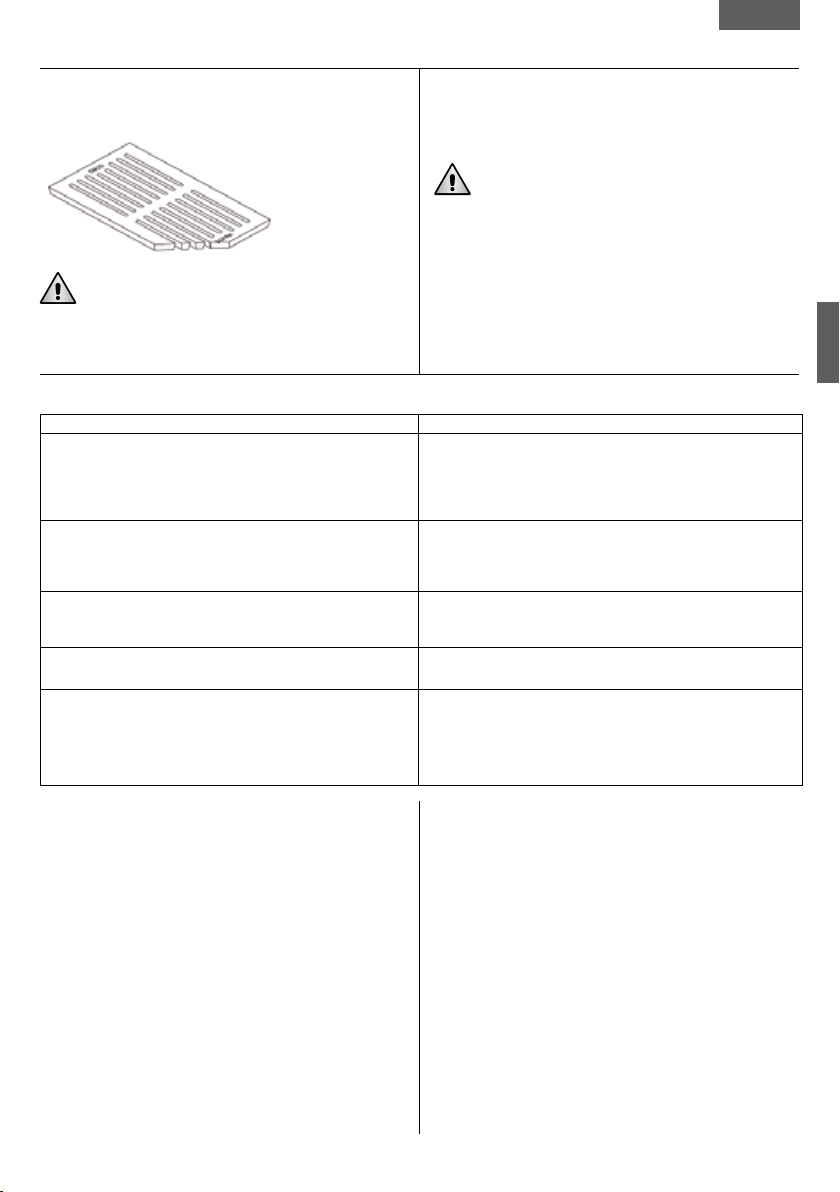
ACCESSORIES PROVIDED
• Scraper for cleaning the flue gas pass
(excluding mod. FK600)
• Bar for moving the rings
• Steel brush
• Baking pan
• Oven glove
• Grill handle (mod. FK600,FK900 and EKB110)
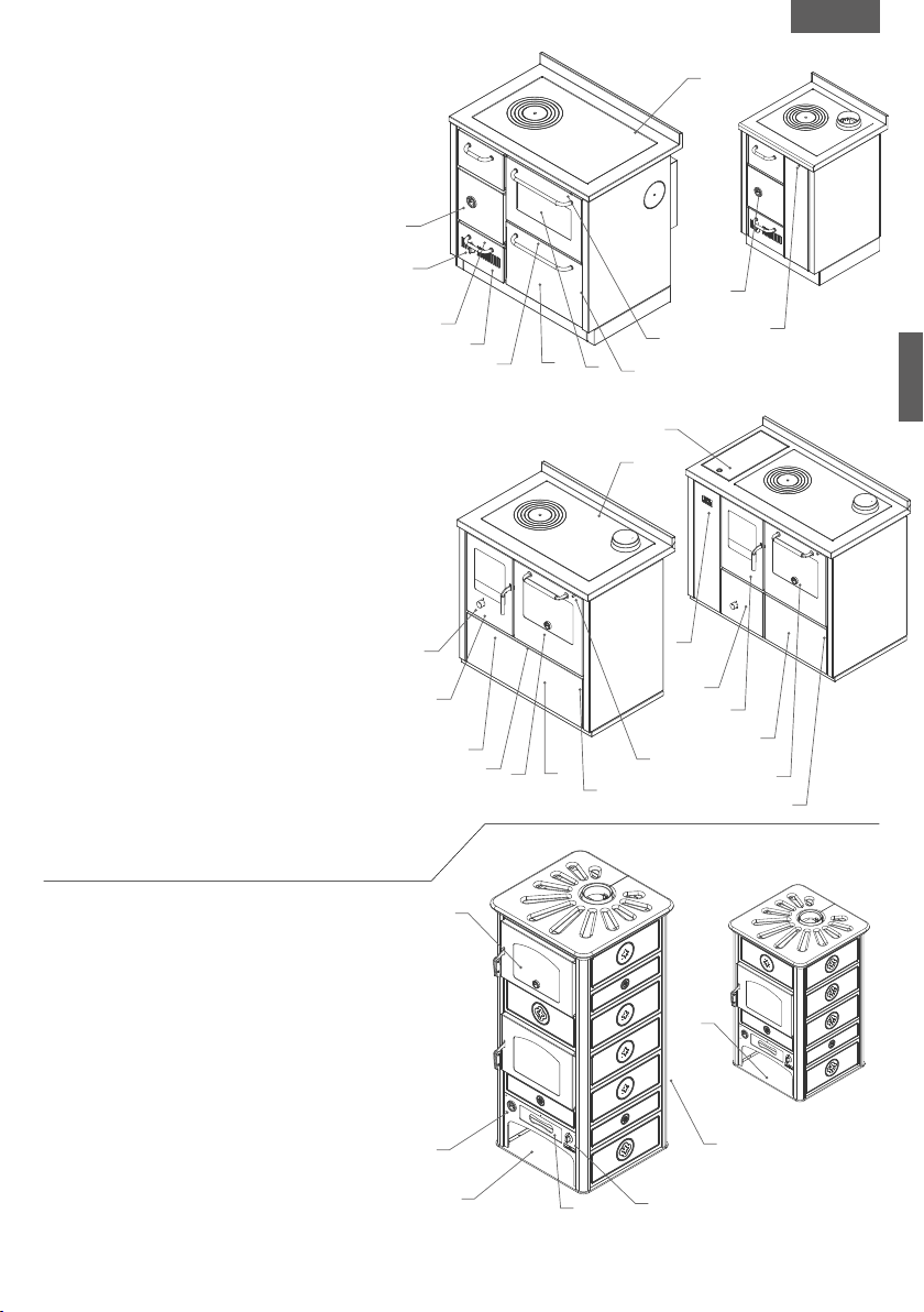
1.4 DESCRIPTION OF THE ECO THERMOCOOKER
a. Cast iron coking plate
b. Height-adjustable hearth grille (mod.EKB110)
c. Oven with thermometer
d. Oven light switch
e. Starter for starting the cooker up from scratch
f. Thermostatic control of the primary air
g. Water heater thermometer
h. Wood drawer
i. Ash drawer
j. Access for cleaning the flue gas circuit
k. Electronic control unit (mod.EKB110)
l. Integrated open tank (mod.EKB110)
1.3 DESCRIPTION OF THE CLASSICA THERMOCOOKER
a. Cast iron coking plate
b. Height-adjustable hearth grille
(excluding mod. FKA900)
c. Oven with thermometer
d. Oven light switch
e. Starter for starting the cooker up from scratch
f. Thermostatic control of the primary air
g. Water heater thermometer
h. Wood drawer
i. Ash drawer
j. Access for cleaning the flue gas circuit
1.5 DESCRIPTION OF THE THERMOSTOVE
a. Oven with thermometer
b. Thermostatic control of the primary air
c. Water heater thermometer
d. Ash drawer
e. Thermostat with contacts for controlling outside equipment
(recirculation pump,etc.); NA – NC contacts
f. Rack container for trays
english
ACCESSORIES PROVIDED
• Baking pan
• Oven glove
FK900
FK600
SK60F-ZK60F
SK60-ZK60
hd
i
b
d
a
e
c
e
b
j
g
g
f
e
a
f
c
f
EKB110
EK90
hdc
d
c
h
b
i
k
j
f
i
ge
a
l
6
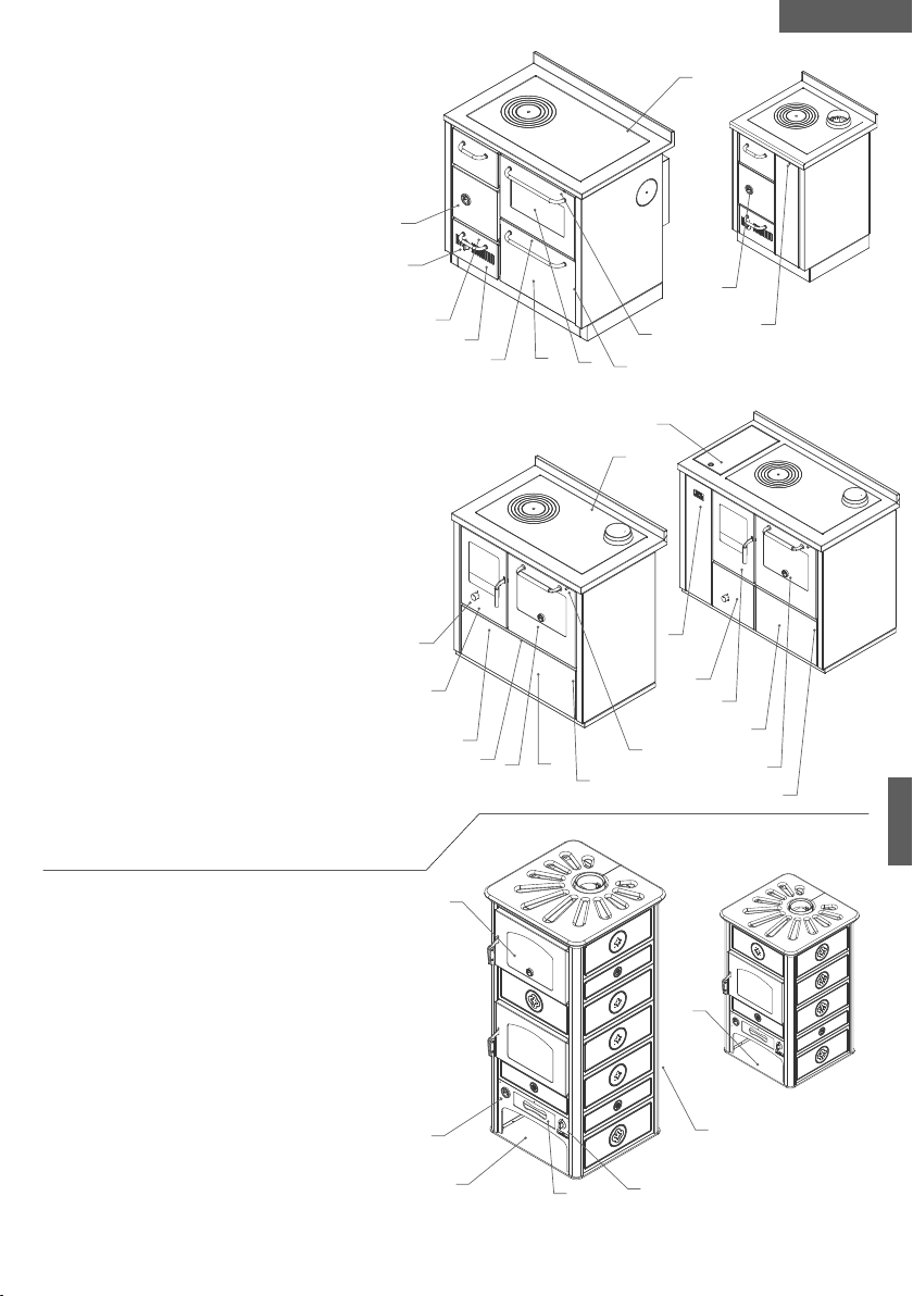
If the cooker is to be installed between other units, leave a
gap of at least 2 mm on each side as the cooker tends to
expand with heat.
For built-in furniture is recommended to use special 25 mm
stainless steel side spacer and if necessary the profile in steel
for the top.
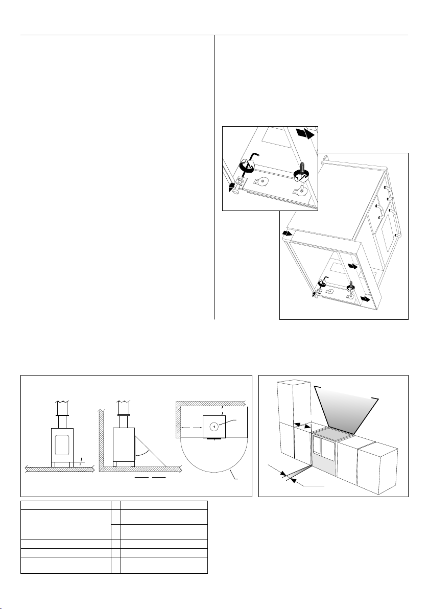
CLASSICA PRODUCTS
Place the cooker on the floor, pull out the wood drawer,
remove the 4 screws on the plinth cover (2 on each side),
remove the plinth cover, install the cooker in the required
position, connect it to the flue, and level the cooker by
adjusting the feet using a 4 mm allen wrench.
The ECO thermocooker has a fixed plinth.
WARNING: failure to comply with these instructions will void
your warranty.
2.1 HANDLING AND INSTALLATION
Make sure the flue is suitable before connecting the cooker
to it (see chapter 2.4).
WARNING: do not lift the cooked by its handrail.
NOTES:
• the appliance must be installed on a floor of sufficient
weight-bearing capacity. If it is not satisfactory, take the
appropriate measures (e.g. weight distribution plate);
• the appliance must be installed to ensure easy access for
cleaning the same appliance, the gas discharge pipes and
flue pipe.
• the appliance cannot be connected to a shared flue pipe.
• air extraction devices must not be used in the same room as
the appliance, unless there is a suitable air ventilation
system.
• install the appliance in a room of a size suited to its potential
and that is sufficiently ventilated (window or specific air vent).
2. INSTALLATION
45 °
R
D
R
P
L
45 °
R
D
R
P
L
45 °
R
D
R
P
L
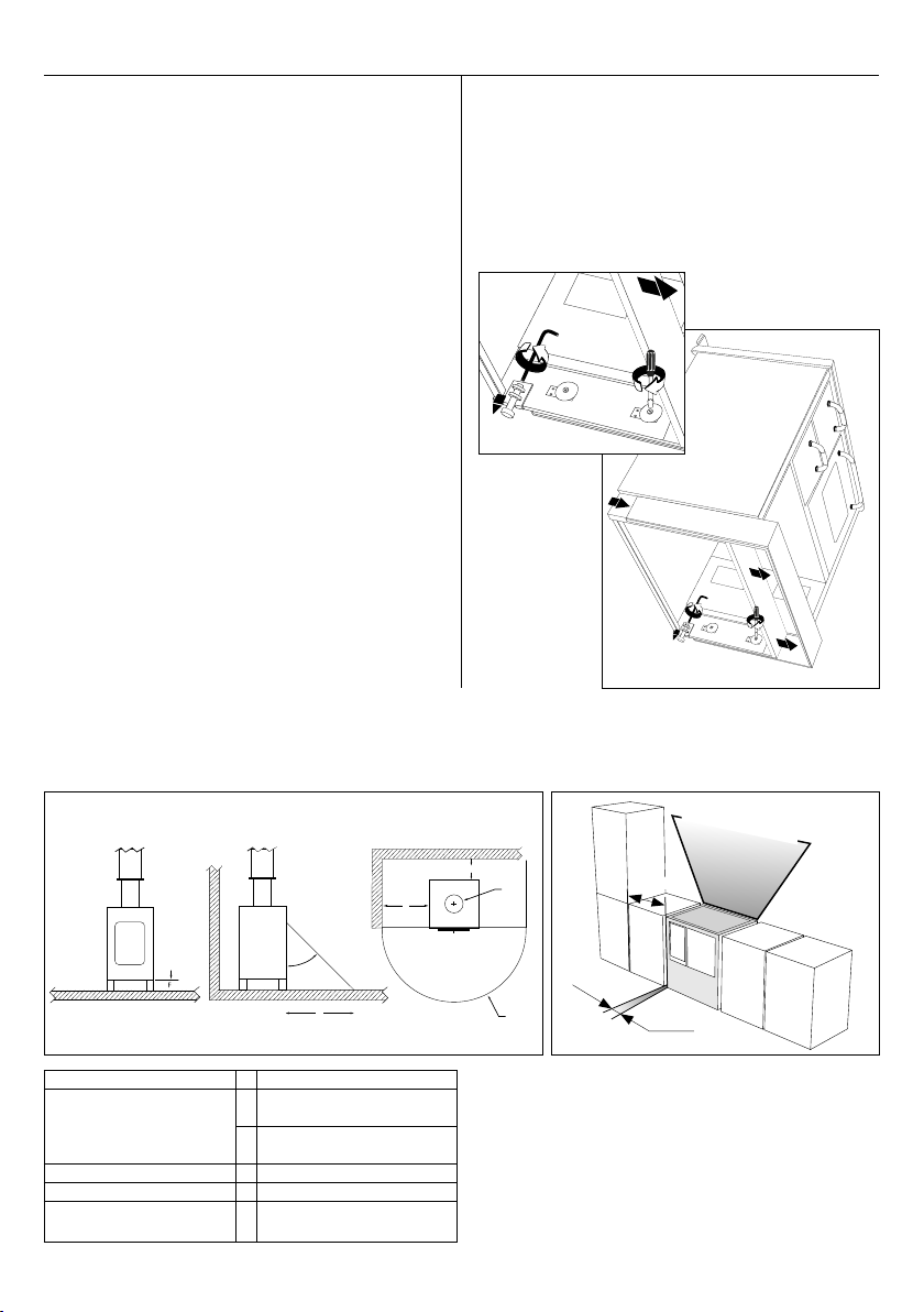
2.2 SAFETY CLEARANCE FROM INFLAMMABLE MATERIALS
From the side wall L600 mm
From rear wall
P200 mm + reflective steel
plate of 20/10
P0 mm + 80 mm calcium
silicate insulating board
Floor F0 mm
Front
R> 600 mm
Minimum distance air from
inflammable built-in furniture
C25 mm
C=25 mm
L=600 mm
High temperature zone

7
2.3
ECO SERIES:
ADJUSTING THE FIREDOOR LOCK
• use a Phillips screwdriver to undo the top and bottom screws
• use a 3 mm hexagonal allen wrench and:
- tighten to reduce play of the closure
- loosen to increase play of the closure
• re-attach the two screws
2.4 THE FLUE SYSTEM
FLUE PIPE CHARACTERISTICS
It is essential that the flue is suitable for the appliance to
work correctly.
The flue system should be inspected by a technician expe-
rienced in flues before installing the appliance, and then be
checked at least once a year.
The flue pipe must conform to the regulations in force
and be kept in perfect condition.
Below are several instructions on fitting the flue pipe.
Non-compliance with these could compromise the applian-
ce’s yield and cause problems with combustion:
• Its height must not be less than 4/5 linear metres from
the connection to the stove to the base of the chimney pot;
the flue can be narrower if its height is any greater.
• It must be properly sealed and insulated; make sure the
inspection panels close properly and that there are no cracks
on any part of the flue pipe.
• The inside of the pipe must be smooth and the same width
all the way up.
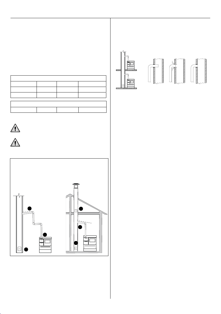
• The flue must be as straight as possible and the chimney pot
must be in a suitable position and at an appropriate pitch, as
indicated in the diagrams and examples below.
• The chimney pot must be double the width of the flue pipe.
FLUE PIPE DIMENSIONS
Guideline for sizing the flue as a function of it’s height:
FLUE PIPE (H) THERMOCOOKERS THERMOSTOVES
< 4 m Draw not
guaranteed Draw not
guaranteed
4 m < 6 m Ø 160 mm Ø 200 mm
> 6 m Ø 150 mm Ø 180 mm
If this is not feasible you should contact a flue specialist.
CROSS-SECTION: the flue pipe’s cross-section depends on
the height of the flue and the thermal power of the installed
cooker.To ensure the optimal yield of our cookers we recom-
mend you use circular flue pipe with smooth interior lining
and of the same length all the way up.
INSULATION: flue draught pressure also depends on the dif-
ference in the temperature of the hot flue gases and that of
the air outside.The flue pipe must be insulated to restrict
absorption of heat into the walls and therefore avoid conden-
sation, which can cause tarry residues. Use only suitable heat-
and corrosion resistant materials conforming to building and
fire-prevention regulations.You should not use flue pipes
comprising simple or flexible metal tubes, cement tubes for
vents, etc.
DEPRESSION: the optimal depression (flue draught
pressure) is 0.15 mbar.
a. Flue’s refractory
interior lining or
stainless steel
(min.T400)
b. Prefabricated
external casing
c. Insulation material
c
d
Roof
pitch
Reflux area
0.5 m above
the ridge
b
Roof pitch
15° adistance > 1,85 m bdistance 1,85 m
c1 m min. d0,5 m
30° adistance > 1,3 m bdistance 1,3 m
c1,2 m min. d0,8 m
45° adistance > 1,5 m bdistance 1,5 m
c2 m min. d1,5 m
60° adistance > 1,2 m bdistance 1,2 m
c2,6 m min. d2,1 m
a
english
8
• the pipe must not be narrower at the end;
• the end of the pipe must not protrude into the flue.
At a depression below 0.15 mbar, the fire will burn too slowly
and form carbon residue excessive gases.If instead
depression is any greater, combustion will be too fast and not
transmits much heat to the boiler, the heating plate and the
oven, and will make large operating times impossible.
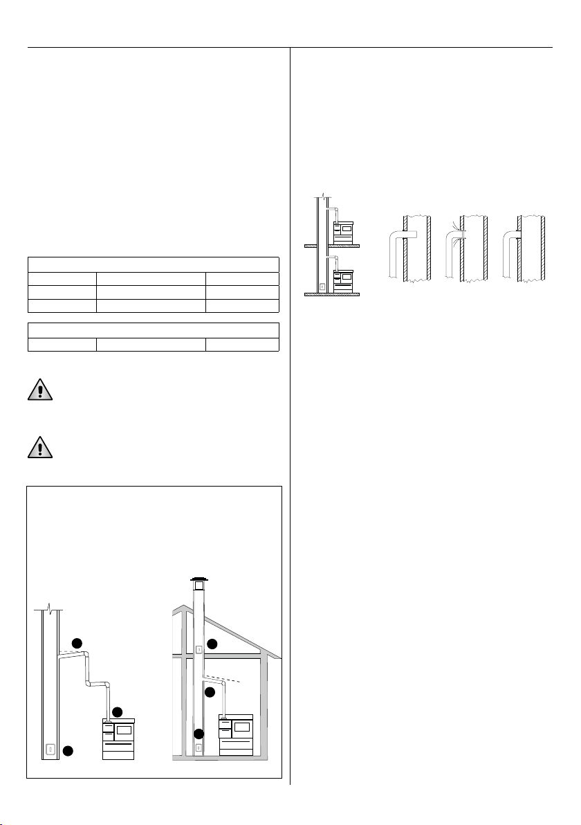
CONNECTION TO THE FLUE PIPE
The cooker is delivered with the connection corresponding to
the flue exit chosen when ordering:
EACH COOKER SHOULD HAVE ITS OWN FLUE PIPE; DO NOT
USE THE SAME FLUE PIPE FOR MORE THAN ONE APPLIANCE.
THE COOKER SHOULD BE CONNECTED TO THE FLUE PIPE
AVOIDING AS FAR AS POSSIBLE ANY BENDS, DIVERSIONS AND
DOWNWARD OR HORIZONTAL SECTIONS.
Connecting pipes must be perfectly sealed to each other and
to the stove and flue pipe.These precautions must be taken:
• use a seal to avoid infiltration of air into the flue;
THERMOCOOKERS
Above Fix Cast Iron Ø 140 mm
Rear Fix Cast Iron Ø 140 mm
Side Telescopic Steel Ø 140 mm
THERMOSTOVES
Above FiX Steel Ø 150 mm
2.5 HYDRAULIC CONNECTION TO THE HEATING
SYSTEM
The appliance must be installed by a qualified hydraulic
technician in accordance with regulations on cookers
that use solid fuels.
Thermocookers and thermostoves are endowed with boiler to
use the heating produced by the device through a system
with fluid vector for heating and for the production of hot
water.The appliance must be designed according to UNI
10412-2:2006 law by a qualified thermal technician and
must be installed by experienced people according to exist-
ing laws in particular to UNI 10683:2005 law.
The appliance are endowed with all the necessary predisposi-
tions for a correct installation, every external component (as
pumps, valves, acoustic alarms, pressure switches) must be
obtained by third parts according to the specifies of designer
and installer.
Before the lighting of the thermal cooker it is compulsory to
make the connections to the heating system.The use of the
appliance with empty or not connected to the system boiler
causes the irreversible damaging of the boiler itself.
Anyway, it is necessary to connect the going connector, the
return connector and the discharge connector (necessary to
empty the boiler in case of maintenance), the other connec-
tors according to the kind of system that you make could be
not necessary and so in this case you must cover them.
DeManincor accepts no liability for damage or harm to
objects or persons if the system is not fitted properly or does
not respond to regulations in force.
YESNO
1. Pipe is too long and
on inclined plane
2. Pipe narrower than outlet hole
3. Leaky cleaning panel
4. Sealed connections
5. Inspection
6. Cleaning
3
1
2
5
4
6
+ 3 %
Pipe too
far in Unsealed
connection correct
connection
NO NO YESNO
9
RECOMMENDATIONS
• the detailed design of the system must be carried out by a
heating engineer.
• we recommend applying simple patterns of proven
effectiveness and providing the system with useful elements to
check correct operation: temperature probes, mixing valves,
thermometers, etc.;
• the heat distribution circuit (radiators or radiant floor panels)
must be designed to prevent the return line from entering
directly into the boiler;
• provide for an adequate anti-condensation circuit or a
lukewarm return line: the supply temperature of the boiler
water should be kept at about 70/80°C with a return line not
below 55°C;
• we recommend using a heat storage tank to increase the
autonomy between one charge and the next one and absorb
the peaks of energy;
• at regular intervals, it is advisable to clean the combustion
chamber and heat exchangers inside the boiler to keep them in
good working order.
INSTALLATION MODES
The technical law UNI 10412-2 has introduced the possibility to
install the solid combustion based devices matched with devices
with closed expansion tank, endowed with thermal discharge with
emergency exchanger inside the boiler. Thermal cookers and ther-
mal stoves are endowed with all the predispositions for the ther-
mal discharge.
Thermocookers and thermostoves can be installed with open
expansion tank.
SAFETY
On every solid combustible based boilers it is not technically
possible to break the combustion immediately as happens
for boilers based on liquid or gas combustible according to
necessity. For this reason, it is mandatory to swallow always
the produced heating also even if the heating system does
not request that and also in case of lack of AC power. On
contrary, the water in the boiler could boil without possibility
of outlet, with serious danger of explosion of the boiler and
serious injury risk for the people present near the thermal
cooker. For this reason,we recommend to follow strictly the
norm UNI 10412-2, in the various cases. We also suggest
inserting a boiler/puffer in the hydraulic system in order to
accumulate the heating.
Here below you find a few examples of installation diagrams.
The system should be designed by a heating technician.
CONNECTION TO A CLOSED SYSTEM
According to standard UNI 10412/2 (March 2009), a solid
fuel appliance can be installed on a closed water piping sys-
tem providing the appliance has a thermal discharge system
with additional circuit in the heater (coil).
The thermal discharge system allows to cool directly the boil-
er when it is necessary by making flow cold leaking water in
a separate circuit inside the boiler.
All the components of the thermal discharge system external
to the thermal cooker must be obtained by third parts accord-
ing to the specifies of designer and installer.
To make this auxiliary system it is necessary to make the
going and return connections, the detector that rules the
device must be inserted in the apposite connection bulb.The
system, to be effective, must be able to work and must have
availability of cold water also in case of lack of AC power.
All safety devices must be accessible after installation of the
appliance in order to guarantee proper maintenance and
functional verification. Functionality of equipments must be
regularly checked: at least once per year.The thermal dis-
charge circuit must not be used for the production of hot
water for domestic use.
The thermo stoves and thermo cookers FKA900 and EK90
are already configured for closed-cup installation,as they
always have an exchanger with a built-in coil.
Standard cookers FK600 and FK900 are not equiped with a
thermal discharge system in their boiler. So, you have to
clearly specify if you need it when ordering the cooker.
The FK80P, FK110P and FKA110P models have a safety sys-
tem with thermal discharge, safety valves, pumps and plate
exchangers to separate the primary and secondary circuits
and instantly produce domestic hot water.
Along with the anti-condensation function, these models, fit-
ted with an electronic control unit, allow for interaction with a
gas boiler.
As the EKB110 model has a built-in open cup, it does not
require additional safety systems.
english

10
To reduce condensation on the walls of the combustion
chamber,the temperature of the return water should be
kept above the minimum temperature of 55°C.
If fitting a control thermostat for the recirculation pump, set
the intervention value to 65˚C..
CONNECTION TO AN OPEN-CUP SYSTEM
If they do not feature a safety thermal discharge:
THE DEVICE MUST BE CONNECTED TO AN OPEN
HYDRAULIC CIRCUIT
for automatic protection against overheating in the event of a
fault or a block or a power cut affecting the circulation pump.
VSP= Overpressure valve T= Thermometer M= Manometer
CONNECTION TO A CLOSED SYSTEM
Cold water
C
M
Y
CM
MY
CY
CMY
K
impianto 2.2_ita.pdf 1 17/07/14 15:14
Drain
Thermic
exhaust valve Thermostove
Thermocooker
Circulating
thermostat
Feed
Feed Collector
Return Collector
Cold water
Hot sanitary water
Boiler
Closed
expansion tank
Anti-condensation
valve
Return
C
M
Y
CM
MY
CY
CMY
K
impianto 1.pdf 1 17/07/14 15:14
Open expansion tank
Cold water
Hot sanitary water
Boiler
Feed
Collector
Return
Collector
Circulating
Thermostat
Feed
Return
THERMOCOOKER
OR
THERMOSTOVE
Loading duct
Safety
duct
Anti-condensation Valve

11
3. INSTRUCTIONS ON USE
INITIAL NOTES:
• do not use the appliance as an incinerator or in any way for
which it was not intended;
• do not use fuel other than that recommended;
• do not burn any plastics or treated wood (such as chipboard)
or textiles;
• do not use liquid fuel;
• the appliance, especially its outer surfaces, can become
extremely hot to the touch when in use; handle with care to
avoid burning yourself;
• do not put any plastic bottles or spray cans on top or in the
immediate vicinity of the appliance (risk of fire and
explosion);
• warn children of the risks and keep them away from the stove
when it is in operation;
• do not make any unauthorized changes to the appliance;
• do not put in too much fuel as this can produce excessive
heat and overheat the appliance, causing potential damage;
• use only original spare parts approved by the manufacturer.
WHATTO DO IN THE EVENT OF A FIRE IN
THE FLUE PIPE
The use of damp and inappropriate fuel or operating the
stove at too low a capacity can cause easily inflammable sub-
stances, such as and soot, to accumulate in the flue pipe.
This can in the long term be a potential cause of fire in
the flue pipe!
In the event of this happening:
• shut off the flow of primary and secondary air;
• make sure everybody leaves the apartment or house;
• call the fire brigade (telephone number: 115 in Italy).
FUEL
The appliance is designed for burning solid fuel: wood,
blocks of compressed wood and lignite briquettes. We
recommend you use reasonably small pieces of wood that
have been seasoned for at least two years in a ventilated and
covered area.They should ideally measure 6-10 cm in diame-
ter and 25-30 cm in length.
We advise you bring wood into the house a few days before
burning it so the heat in the home will dry it out more
quickly.
INITIAL USE
The flue system should be inspected by a technician expe-
rienced in flues before installing the appliance, and then be
checked at least once a year.
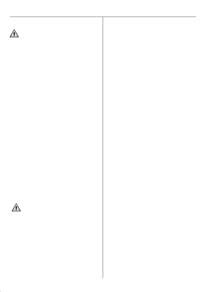
CHECK THE GRILL IS IN ITS CORRECT POSITION IN THE
HEARTH: THE NARROW END OF THE SLITS SHOULD
FACE UPWARDS.
3.1 OPERATING INSTRUCTIONS
WARNING: when you use the cooker for the first time, it is
normal for condensation to form due to humidity in the
refractory materials. Start with a small fire and keep the fill
opening and ash drawer ajar for a few hours to encourage
evaporation.
If condensation persists the causes could be as follows:
• use of wet, very damp or unseasoned wood;
• flue defects that let the gases cool down and create
condensation; these defects should be found and eliminated;
• return water temperature under 55°C due to too low a
fire or because the system is absorbing too much heat:
prepare the anti-condensation circuit.
IMPORTANT:
CONSTANT CONDENSATION AFFECTS THE
THERMOCOOKER’S YIELD AND THE DURATION OF THE
HEAT EXCHANGER, FORFEITING THE GUARANTEE.
LIGHTING A FIRE WHEN THERE IS NO WATER IN THE
CIRCUIT AND IN THE BOILER CAN CAUSE SERIOUS,
IRREPARABLE DAMAGE TO THE HEATER.
INITIAL START-UP
In order to make easier the fire ignition in a cold appliance
it is necessary to:
• (thermocookers) raise the grill to its highest position using
the respective handle;
• (thermocookers) pull the starter to let the gases enter the flue
pipe directly;
• fully open the primary air source, by turning the control
unclockwise all the way round;
• load the kindling and igniting material: balls of newspaper
or other small dry fuel;
• light the fire;
• WARNING: (hearth with glass door) to prevent the glass
from getting dirty leave the door ajar with the handle in
closed position (see photo 5) and wait for ten minutes or so
for the glass to heat up and thereby avoid condensation on
the inside due to the difference in the temperature of the
flames and the internal surface of the glass;
• when the fuel is burning brightly and the flue has heated up
sufficiently (this may take 30 minutes or more), close the
starter and put in some larger pieces of wood.
In certain situations, as when lighting the fire for the first time in
the day or when there is poor flue draught pressure due to bad
weather, it is not a bad idea to leave the ash drawer slightly ajar.
DO NOT USE ALCOHOL OR OTHER FUELTO ENCOURAGE
OR SPEED UP THE FIRE.
english
12
OPERATING INSTRUCTIONS
LIGHTING THE FIRE IS THE MOST CRITICAL PHASE FOR
GENERATING FLUE DRAUGHT PRESSURE; AFTER THIS YOU
SHOULD KEEP MONITORING THE FIRE.
It is possible that the wood will not catch fire and that
your initial fire might go out after a few minutes.This is
because the flue pipe is cold and there is insufficient flue
draught pressure.Start your fire again using easily
combustible material: thin dry sticks, shrubs, pine cones and
newspaper are ideal for this first phase.
When the wood has caught fire, regulate the primary air
supply by turning the thermostatic control, so that the logs
burn well with tall flames. Avoid too great a flue draught
pressure but also don’t let combustion get too slow as this
can result in the deposit of soot in the stove.
Make sure there is always a good bed of glowing
embers at the bottom of the stove and add wood as soon as
the previous logs have turned into embers: the bed of
embers maintains the temperature required for igniting
more wood and ensures correct combustion.Always arrange
the logs crosswise so that air can pass between them and
ensure good oxygenation.Try and keep the flames burning;
most heat is generated by the combustion of the gases. If the
flames die down completely, unburned gases are produced
that waste energy and pollute.
COMBUSTION SPEED
You can adjust the air control devices and grill to increase or
decrease combustion speed and therefore the heating or
cooking temperature:
• Fast combustion: primary air control open (fully
anticlockwise)
• Slow combustion: primary air control closed (fully clockwise)
• In the summer: (thermocookers only) if minimal heat is
required, for cooking and hot water only, it is a good idea to
raise the fire grill to its highest position as this limits the
combustion chamber and helps to save on fuel.
AVOID OVERLOADING THE APPLIANCE.
A relatively small and well oxygenated fire will burn better
and produce more heat than a large stack of wood blocking
the hearth.
IMPORTANT: during fast combustion make sure there
is no more than 3 kg of wood in the stove at all times.
A greater amount of fuel requires you to reduce the
combustion speed proportionally by acting on the
air control.
Adding more fuel without changing the combustion speed
will produce thermal power greater than the cooker -environ-
ment exchange capacity. This will not only waste fuel but
could also damage and deform the appliance.
The ideal load for efficient and clean combustion is 3-4 kg of
wood per hour for thermocookers and 4-6 kg for thermosto-
ves. Bigger loads go to the exclusive benefit of operating
times.
Excessive residual ash quantity indicates a poor combustion.
Transparent smoke coming out of the chimney indicates a
clean burning, whilst opaque or dark smoke shows an excess
of unburned material.
WARNING: Thermal shock caused by a sudden increase in
temperature can form small cracks in the refractory bricks.
These cracks will not compromise the structure and resistance
of the bricks or cooker in any way.
When combustion has ended, close the primary air lever
and any secondary air slits to prevent the heat in the stove
escapes with the flow of air in the flue.
Lack of flue draught pressure. A column of cold air could
form in the flue pipe for a variety of reasons. These could be
low atmospheric pressure, humidity, strong winds or
depression in the house (e.g. if the hood above your kitchen
stove is switched on).
In the event of low atmospheric pressure or rain,the flue
draught pressure will not be nearly as good as on a clear day
or during a cold, dry winter. Humidity can also form in the
flue pipe if the stove is not used for a long period of time. It
is worth keeping the stove’s doors ajar to let air circulate in
the flue pipe.
3.2 USING THE OVEN
The oven always needs to be pre-heated for cooking.Add a
suitable amount of fuel to the combustion chamber, open
the primary air control to obtain the required temperature.
Leave the fire to burn for about an hour with the primary air
valve open and then wait for about ten minutes after the fla-
mes have died down in the combustion chamber.
Keep the temperature constant by adding thin wood to the
stove measuring about 3 cm in diameter at a rate of one or
two pieces every ten minutes.
3.3 USEFUL NOTES
COOKING PLATE
The cast iron cooking plate must never become incandescent.
Always use receptacles with flat heavy bases (for
maintenance see chapter 4.2)
HEARTH GRILL
Poking the embers on the iron grille in the combustion
chamber will make the ash fall through into the ash drawer
below.This clears the way for the supply of primary air to the
combustion chamber – particularly important when starting
up your fire.
The slits in the grill have two specific functions: they let
combustion air pass through and, at the same time, enable
the disposal of the embers and ash.
13
3.4 TROUBLESHOOTING
THE VARIOUS REASONS THE STOVE MIGHT NOT
WORK PROPERLY
THE FLUE PIPE
• Too short. The flue pipe stretches from the connection with
the stove to the base of the chimney pot. If the flue pipe is too
short, increasing its internal width will never compensate for
the reduction in height as that will only increase heat
dispersion, lower the temperature of the gases and potentially
compromise flue draught pressure. You are better advised to
use a flue pipe of the correct width and increase its height by
1 or 2 metres to ensure decent flue draught pressure.
• Too long. This doesn’t generally affect flue draught pressure;
however the flue pipe should be well INSULATED to minimize
heat dispersion.
• Too wide. A flue pipe that is too wide will have a
proportionally larger surface area that will encourage the
gases to cool down and therefore compromise flue draught
pressure. One option is to put a stainless steel pipe of
suitable width inside the existing flue pipe and, after
connecting it to the stove, fill the gap between the two pipes
with heat-resistant granular insulation material.
• Too narrow. IToo narrow. In this case you will not be able to
exploit the stove’s potential. We can only suggest that you
reconstruct the flue pipe according to the required
specifications.
• Tight sections. Changes in the pipe’s width will cause a loss
of flue draught pressure, slowing down and potentially
preventing the gases from leaving the flue.
• Too many bends. Bends cause a loss of flue draught
pressure, preventing the gases from leaving the flue. For each
bend you need to increase the height of the flue pipe by 50
centimetres so as to ensure optimal flue draught pressure.
• Excessive deviations. Deviations affect the discharge of
gases and should generally be avoided.
The slits are wide enough to let through the ash and any
dead embers; while the walls of the slits are conical so as to
not block the flow of air.
THE GRILL MUST BE POSITIONED WITH THE NARROW
SIDE OF ITS SLITS FACING UPWARDS.
INTERNAL ASH DRAWER
The ash drawer must be emptied on a regular basis to
prevent the iron grill from overheating.
THERE MAY STILL BE SOME GLOWING EMBERS
IN WITH THE ASH.
PROBLEM POSSIBLE CAUSE
The stove does not work
It is not connected properly to the flue
The flue pipe does not conform
Other appliances are connected to the flue pipe
The hearth grill is the wrong way round
The hearth grill is blocked with ash
Smoke comes out of the plate
No flue draught pressure
It is not connected properly to the flue
The starter and/or primary air valve is closed
The plate’s seals have come loose or are broken
Condensation in the hearth The wood is damp or not properly seasoned
The flue is too wide
Poor flue draught pressure
The fire lights with difficulty The starter is not fully open
The flue is cold (due to a long period of inactivity)
The oven does not get sufficiently hot
Poor or insufficient flue draught pressure
The internal pipes are clogged
The starter is open
Excessive flue draught pressure
english

14
4. MAINTENANCE
4.1 ROUTINE CLEANING AND CHECKS
The cooker is at its most efficient when all the surfaces and
pipes the gases come in contact with are kept perfectly clean.
The boiler must be cleaned whenever the yield decreases.
We advise regular maintenance by a qualified technician. Clean
and check the cooking plate and the iron doors’ fibreglass seals
on a regular basis.
All maintenance and cleaning must only ever be carried out
when the stove has fully cooled down::
• (thermocooker) Remove the iron cooking plate and clean
underneath thoroughly with the provided steel brush;
• scratch and brush all surfaces of the boiler;
• (thermocooker) Remove the pressurized door under the oven
and use the small shovel to clean the flue-ways, removing all
the ash at the base (only for mod.FK900);
• vacuum-clean all accessible areas.
CLEANING THE CERAMIC GLASS OF THE
COMBUSTION CHAMBER’S DOOR
Eliminate all traces of soot on the inner side of the ceramic
glass using a soft cloth dampened with a little clean ash, or
with a suitable product in the event of stubborn traces of tar.
Dry well afterwards.
Clean the outer side of the ceramic glass with a damp cloth
or,if necessary, with a little neutral detergent. Dry well
afterwards.
ECO MODELS: EXTRACTTHE OVEN DOOR
• extract the door’s lock using a screwdriver if necessary
• turn the lock to its locking position
• close the door as far as the lock permits
• remove the door by lifting it and pulling it towards you
4.2 MAINTENANCE OF THE COOKING PLATE
When you first use the cooker, the cast iron plate will gra-
dually change colour,starting with the hottest part and, after
a while, the colder parts. The plate eventually becomes all
one colour.Clean the heating plate with any type of deter-
gent; then rinse it only if it is slightly warm so that the humi-
dity can evaporate naturally. Grease the entire plate with a
cloth soaked in oil.
The heating plate is made of iron so prolonged contact with
humidity will cause a thin layer of rust to form on its surface.
This can be removed as follows:
• rub the surface of the plate with 120 grit abrasive paper
• rub the surface with food oil
• clean with a dry cloth.
• Horizontal sections. These should be avoided or kept as
short as possible and always at a minimum gradient of 2 cm
per metre.You are advised to assess the depression to
guarantee sufficient gas evacuation.The flue pipe should be
increased in proportion to requirements.
• Obstruction in the flue pipe. When the stove is not used for
a long period of time, and especially during the summer, you
might find that birds, wasps or bees will nest in the chimney
pot; in which case you will have trouble lighting the stove
again. Moreover,a poorly or improperly made flue pipe may
cause instances of crumbling plaster or cracks through which
air enters.
CLEANING THE FLUE PIPE. THE FLUE PIPE MUST BE
CLEANED ON AN ANNUAL BASIS. THE BEST TIME IS AT
THE END OF WINTER.
AIR RECOVERY
• No air recovery. The stove can still be lit but soon burns up
the available oxygen, reducing combustion and causing the
gases to build up and come out of the stove. The purity of the
ambient air is compromised as a result. In this case you
definitely need an outside air vent.
• Insufficient air recovery. If there is insufficient air recovery,
combustion is poor and gases will come out of the stove
especially when you open the door to add more wood. If the
stove is installed in a room with double-framed doors or
double-glazed windows, a suitable air vent must be installed
to ensure a good flow of air.
OTHER REASONS
• The position is too windy. You need to install a
WINDPROOF chimney pot, otherwise any change in the
direction of the wind will compromise evacuation of the
gases.
• Presence of two flue pipes in the same room or in two
adjacent rooms. The flue pipe with the more powerful
draught pressure will draw the gases from the one with the
least powerful one; as a result gases will come out of the
stove with the poorer flue draught pressure.
• Presence of a ventilating hood in the room. If there is
insufficient air recovery, the air will be retrieved by the stove
causing smoke. If you switch on the hood while the stove is in
use, you must leave a window ajar for all the time the
ventilating hood is in operation.
• Poor connections. Narrow sections, internal edges, imperfect
joints and sharp bends might accidentally be created when
connecting the stove to the flue that could impede the
evacuation of the gases.
• Uninsulated flue pipe. Gases passing through an
uninsulated flue pipe will cool down and compromise flue
draught pressure.This causes atmospheric pollution,
condensation and the deposit of unburned products inside
the pipe, affecting its efficiency.

15
5. GUARANTEE
MANUFACTURER’S DECLARATION
The DeManincor firm guarantees the appliance has passed
all the in-house tests and inspections and that is it therefore
up to standard and without any manufacturing or material
defects.
GENERAL TERMS
The guarantee is valid for 2 years from the date of purchase.
It applies only to the original purchaser and is non-
transferable.The guarantee covers original manufacturing
defects and applies to all of the product’s components.
The warranty on the boiler only is extended to 5 years.
To request a service under the terms of the guarantee, the
customer must present a valid proof of purchase (payment
receipt, invoice, etc.).
CONDITIONS
The request must be made through an authorized dealer.
The DeManincor firm has the final say on what action should
be taken to resolve any problems under the terms of the
guarantee.
Any defective parts that are replaced remain the property of
the DeManincor firm.
The DeManincor has the final say on whether the service
under the terms of the guarantee should be done at the
customer’s or its own premises.
For services offered under the guarantee, the customer is
required to pay the minimum charges according to the going
rates.This is not the case however if the cooker is purchased
less than four months previously.
For repairs at DeManincor’s assistance centres, the customer
is required to pay for the transport costs.
IMPERFECTION OR DEFECT IN THE MATERIALS
Imperfection or defect in the materials must be signalled
within 8 days since the customer receives the products and
anyway this implies only the obligation to replace what
provided, excluding any additional responsibility.
COMPONENTS NOT COVERED BY THE GUARANTEE
The following are not covered:
• damage to parts attributable to negligence, carelessness or
ineptitude, in particular deterioration to the heating plate
caused by improper or lack of maintenance;
• damage to parts attributable to non-compliance with the
instructions in this handbook;
• damage to parts attributable to transportation and failure
to comply with some or all domestic and local regulations;
• damage to parts attributable to improper installation,
insufficient capacity or faults with the electrical, hydraulic
and gas connections, and inefficiency of the flues and
discharge systems;
• the guarantee does not cover parts repaired by anyone not
authorized by the DeManincor firm;
• technical services requested attributable to inefficiency of
the flue and/or connecting pipes are not covered by the
g
uarantee and charged according to the going rates;
• consumer parts like gaskets,glass, grids, refractory bricks, etc.
SERVICES AFTER THE GUARANTEE
Any services after the period of the guarantee or which do
not fall under the terms of the guarantee will be charged
according to the going rates. In this case the cost of any
replacements will also be charged.
RESPONSIBILITY
The DeManincor firm cannot accept any liability for any direct
or indirect harm or damage to persons or objects caused by
product defects if the rules set down by domestic or local law
or by this handbook have not been complied with.
COMPETENT COURT
Disputes and litigations are always settled at the court
of Trento.
PRODUCT MODIFICATIONS
The characteristics of the products described in the
catalogues and this user and maintenance handbook are
purely indicative. DeManincor aims to constantly improve
upon its products and therefore reserves the right to make
any changes and improvements it considers necessary
without obligation for forewarning. DeManincor is also not
obliged to apply previous or current changes to products
already or in the progress of being constructed and assigned
to customers.
4.3 STRUCTURE AND OTHER EXTERNAL PARTS
The stainless steel parts should be cleaned when cold with
neutral detergents or with vinegar in the case of persistent
stains. You must avoid using abrasive or acid products
that could damage the surface. Dry with a soft cloth, fol-
lowing the grain of the glazing.
The external parts can be cleaned easily with water and neu-
tral detergent. Do not use aggressive or abrasive chemical
products; any spills from pans or other should be cleaned
immediately.
english

16
1. IDENTIFICACIÓN DEL APARATO
1.1 PLACA DE IDENTIFICACIÓN
En el costado derecho del cajón de la leña se ha aplicado una placa de identificación que lleva el modelo y el número de
matrícula. Para los modelos sin cajón de la leña la placa está en la parte posterior.
1.2 TABLA DE DATOS TÉCNICOS
NORMAS DE SEGURIDAD
¡LAS NORMAS Y/O INSTRUCCIONES MARCADAS CON ESTE
SÍMBOLO ESTÁN RELACIONADAS CON LA SEGURIDAD!
El uso del aparato de leña puede conllevar peligros que hay que prevenir,
observando las siguientes reglas y precauciones.
• el aparato debe instalarse respetando las reglas descritas en la sección 2
de este manual de instrucciones;
• la instalación tiene que respetar toda la normativa local, incluida la que se
refiere a las Normas nacionales y europeas;
• llevar a cabo la conexión a la chimenea solamente una vez que se
haya comprobado que es adecuada;
• queda terminantemente prohibido utilizar productos químicos
para encenderla, como alcohol, petróleo, gasolina, etc.;
• no efectuar cargas exageradas de combustible; además de emitir
una excesiva cantidad de calor, el aparato será sometido a un
recalentamiento que podría dañarlo;
• la plancha radiante alcanza temperaturas elevadas, alrededor de
400º C; prestar atención y evitar tocarla sin una protección adecuada,
igual que las demás partes, como las puertas del fuego y del horno
y sus pomos, cristales y el tubo de salida de humos;
• en el aparato y en las inmediatas proximidades nunca hay que colocar
botes de plástico ni bombonas con espray (peligro de incendio y
explosión)
• hay que informar a los niños previamente sobre estos
inconvenientes y hay que tenerlos lejos de la cocina cuando esté
encendida;
• a la altura de la boca de carga,colocar un suelo,sobre todo si fuera de
linóleo o de madera,una protección de chapa;
• quemar solamente combustibles naturales, como: madera, tronquitos
de madera prensados y briquetas de lignito;
• no quemar de ninguna manera materiales plásticos,materiales de
leña tratada (por ejemplo, paneles conglomerados) ni productos
textiles;
• llevar a cabo con regularidad la limpieza de la chimenea.
TERMOCOCINAS
CARACTERÍSTICAS TÉCNICAS um
FK600
FK900
FKA900 EK90
EKB110
Dimensiones externas: L x P x H cm 60/80x60x85 90/110x60x85 90/110x60x86 90x60x86 110x60x86
Plancha de cocción: L x P cm 48x45 74x45 74x45 74x45 74x45
Capacidad de la caldera lt 20 20 20 20 39
Peso neto/con embalaje kg 170/185 230/250 230/250 230/250 230/250
Tiro necesario en chimenea mbar 0.12 0.12 0.12 0.12 0.12
Potencia calorífica nominal (max) kw 14 (22) 14 (22) 12 (20) 12 (20) 16,5 (25)
Potencia calorífica al agua (max) kw 10,5 (18) 10,5 (18) 9 (16) 9 (16) 8,8 (15)
Co al 13% O²% 0.21 0.21 0.21 0.21 0.09
Temperatura gas de salida °C 254 254 263 263 230
Flujo gas de salida g/s 20.5 20.5 18.3 18.3 11.0
Rendimiento % 70 70 70 70 85
CONEXIÓN
Superior Ø 140 mm
Posterior Ø140 mm
Lateral Ø 140 mm
CONEXIÓN
Superior Ø 150 mm
TERMOESTUFAS
CARACTERÍSTICAS TÉCNICAS um SK60 ZK60 SK60F ZK60F
Dimensiones externas: L x P x H cm 68x66x108 68x66x108 68x66x145 68x66x145
Capacidad de la caldera lt 26.5 26.5 26.5 26.5
Peso neto/con embalaje kg 260/280 260/280 320/340 320/340
Tiro necesario en chimenea mbar 0.12 0.12 0.12 0.12
Potencia calorífica nominal (max) kw 13.9 (24.5) 13.9 (24.5) 17.1 (26.5) 17.1 (26.5)
Potencia calorífica al agua (max) kw 12.5 (20.5) 12.5 (20.5) 13.4 (20.5) 13.4 (20.5)
CO al 13% O² % 0.06 0.06 0.06 0.06
Temperatura gas de salida °C 205 205 210 210
Flujo gas de salida g/s 12.9 12.9 15.2 15.2
Rendimiento % 85 85 85 85
Diámetro interior chimenea de prueba: D = 150 mm
17
Para las alturas de las conexiones solicite la ficha técnica al revendedor, que también se puede descargar en nuestro sitio de internet.
ACCESORIOS DE SERIE
Con la cocina se entregan de fábrica los siguientes accesorios:
• Rascador para la limpieza de chimenea (exepto mod. FK600)
• Atizador para mover las anillas
• Cepillo de acero inoxidable
• Parrilla y fuente del horno
• Guante para horno
• Manilla para levantar la parrilla (mod. FK600, FK900 y EKB110)
1.4 DESCRIPCIÓN TERMOCOCINAS SERIE ECO
a. Plancha de cocción en hierro fundido radiante
b. Parrilla fogón regulable en altura (mod.EKB110)
c. Horno con termómetro
d. Interruptor luz de horno
e. Starter para encender la cocina en frío
f. Regulación termostática del aire primario
g. Termómetro de temperatura del agua en la caldera
h. Cajón provisión leña
i. Cajón cenizas
J. Acceso limpieza recorrido humos
k. Unidad de control electronica (mod.EKB110)
l. Vaso abierto integrado (mod.EKB110)
1.3 DESCRIPCIÓN TERMOCOCINAS SERIE CLASSICA
a. Plancha de cocción en hierro fundido radiante
b. Parrilla fogón regulable en altura (exepto FKA900)
c. Horno con termómetro
d. Interruptor luz de horno
e. Starter para encender la cocina en frío
f. Regulación termostática del aire primario
g. Termómetro de temperatura del agua en la caldera
h. Cajón provisión leña
i. Cajón cenizas
J. Acceso limpieza recorrido humos
1.5 DESCRIPCIÓN TERMOESTUFAS
a. Horno con termómetro
b. Regulación termostática del aire primario
c. Termómetro de temperatura del agua en la caldera
d. Cajón cenizas
e.
Termostato con contactos preparados para mando del aparato
externo (bomba de recirculación, etc.); contactos NA – NC.
f. Zona de almacenaje leña
g. Acceso limpieza recorrido humos
ACCESORIOS DE SERIE
• Parrilla y fuente del horno
• Guante para horno
EKB110
EK90
FK900
FK600
SK60F-ZK60F
SK60-ZK60
hd
i
hd
b
d
a
e
c
c
d
c
e
h
b
b
i
k
j
j
f
i
g
g
g
f
e
e
a
l
a
f
c
f
español
18
En caso de que la cocina se introduzca al lado de otros
muebles, dejar al menos 2 mm de distancia por cada
lado,ya que con el calor las dimensiones de la encimera de
la cocina podrían aumentar por efecto de la dilatación.
Para encajarla entre los muebles, se aconseja utilizar la corre-
spondiente aleta aireada y si fuera necesario, el perfil de acero
inoxidable para la placa.
PRODUCTOS SERIE CLÁSICA
Colocar la cocina en el suelo,sacar el cajón de leña, quitar
los 4 tornillos que sujetan el cubre-zócalo (2 en cada lado),
quitar el cubre-zócalo, posicionar la cocina y efectuar el
enganche a la chimenea, nivelar la cocina ajustando las
patas a la base mediante una llave Allen del 4.
ATENCIÓN:no respetar estas indicaciones anula la garantía.
2.1 MOVIMIENTO Y COLOCACIÓN
Llevar a cabo la conexión a la chimenea solamente una vez
que se haya comprobado que es adecuada, como se describe
en el capítulo 2.4.
ATENCIÓN: no levantar la cocina cogiéndola por el tirador.
ADVERTENCIAS:
• el aparato tiene que estar instalado en un suelo con una
capacidad de carga adecuada. Si la construcción existente no
cumple este requisito, deberán tomarse medidas adecuadas
(ej. plancha de distribución de carga)
• la instalación del aparato tiene que garantizar un fácil acceso
para la limpieza del mismo,de los conductos del gas de salida
y de la salida de humos
• el aparato no es adecuado para instalarlo en una salida de
humos compartida
• los dispositivos de extracción del aire no deben ser usados en
la misma habitación del aparato, a menos que haya una
adecuada alimentación de aire de ventilación
• colocar el aparato en un local de dimensiones adecuadas según su
potencialidad,ylosuficientementeventilado(ventanaotomadeaire
específica)
2. INSTALACIÓN
De la pared lateral L600 mm
De la pared posterior
P200 mm + plancha en acero
reflectante de 20/10
P0 mm + 80 mm
panel ignífugo
de silicato de calcio
Del suelo F0mm
Frente
R> 600 mm
Distancia mínima en aire de
mueble empotrado inflamable
C25 mm
45 °
R
D
R
P
L
45 °
R
D
R
P
L
45 °
R
D
R
P
L
2.2 DISTANCIAS DE SEGURIDAD DE MATERIAL INFLAMABLE
C=25
mm
L=600 mm
Zona sometida a altas temperaturas

19
2.3
SERIE ECO:
REGULACIÓN DEL BLOQUEO DE LA
MANILLA DE LA PUERTA DE FUEGO
• con un destornillador de estrella, aflojar el tornillo superior y
inferior
• mediante una llave Allen hexagonal del 3:
- apretar para reducir el juego del cierre
- apretar para reducir el juego del cierre
• fijar los dos tornillos anteriormente aflojados
2.4 LA SALIDA DE HUMOS
CARACTERÍSTICAS DE LA SALIDA DE HUMOS
Uno de los elementos más importantes para el correcto funciona-
miento del aparato es una chimenea adecuada.
Llamar a un técnico preparado (un fumista) antes de la insta-
lación del aparato para que controle el equipo de humos y
también periódicamente, como mínimo una vez al año.
La salida de humos tiene que realizarse respetando las
normas vigentes y debe mantenerse en perfecta eficiencia.
Se recuerdan algunas de las características fundamentales de
la salida de humos que,si no se respetan, podrán disminuir el
rendimiento del aparato y crear problemas a la combustión:
• la altura nunca debe ser inferior a los 4/5 metros lineales,
medidos desde la conexión de la cocina hasta la base del
caballete; cuanto más aumente la altura, menor podrá ser la
sección
• tendrá que estar bien aislada y perfectamente estanca;
controlar el cierre de las portezuelas de inspección y que no
haya grietas en toda su superficie
• paredes internas lisas y sección constante en toda su longitud
• la chimenea tiene que estar realizada de la manera más vertical
posible y tener un caballete adecuado para que sobresalga
adecuadamente desde la vertiente del tejado en relación con su
inclinación y su posición, como se muestra en los siguientes
esquemas y ejemplos
• el caballete tendrá que tener una sección de salida doble
respecto a la de la salida de humos.
DIMENSIONES DE LA SALIDA DE HUMOS
Indicaciones aproximadas para las dimensiones de la salida
de humos en función de la altura:
SALIDA DE HUMOS [H]
TERMOCOCINAS TERMOESTUFAS
< 4 m
Tiro no garantizado Tiro no garantizado
4 m < 6 m Ø 160 mm Ø 200 mm
> 6 m Ø 150 mm Ø 180 mm
En caso de que no se pudieran respetar estas dimensiones, pón-
gase en contacto con un técnico fumista.
SECCIÓN: la sección de una salida de humos depende de la
altura de la chimenea y de la potencia térmica de la cocina
instalada. Para obtener las mejores prestaciones de nuestras
cocinas, se aconseja usar salidas de humos con forma circu-
lar,con paredes internas lisas y de sección constante durante
toda su longitud.
AISLAMIENTO:
el tiro de una chimenea depende también
de la diferencia de temperatura de los humos calientes con
el aire exterior. Es importantísimo aislar el cañón de la salida
de humos para limitar la absorción de calor de las paredes,
evitando de este modo fenómenos de condensación con for-
mación de depósitos de alquitrán. Use solamente materiales
adecuados, resistentes a la temperatura y a la corrosión, y
que respondan de todas maneras a todas las normas de fab-
ricación y prevención contra incendios. No son adecuadas las
salidas de humos en tubo metálico sencillo o flexible, en
tubo de cemento para respiraderos,etc.
español
a.
Chimenea interna en material
refractario o en acero
inoxidable (min. T400)
b.
Bloque exterior prefabricado
c.
Aislante
a
c
d
Inclinación
techo
Zona de
reflujo
0.5 m
por encima de la
cumbre
b
Inclinazione
tetto
15° adistancia > 1,85 m bdistancia 1,85 m
c1 m min. d0.5 m
30° adistancia > 1,3 m bdistancia 1,3 m
c1,2 m min. d0.8 m
45° adistancia > 1,5 m bdistancia 1,5 m
c2 m min. d1,5 m
60° adistancia > 1,2 m bdistacia 1,2 m
c2,6 m min. d2,1 m
20
Los tubos de conexión tienen que estar perfectamente sella-
dos entre ellos y en las conexiones con la cocina y la salida
de humos, prestando atención, por lo tanto a las siguientes
precauciones:
• presencia de un florón de empalme para evitar infiltraciones
de aire en la chimenea;
• la sección del tubo terminal nunca debe reducirse;
• el terminal no debe penetrar en el cañón más allá del grosor
de la pared de la chimenea.
CAÍDA DE PRESIÓN:
la caída de presión (tiro) optima necesa-
rio para las cocinas de DeManincor es de 0,12 mbar.
Con valores inferiores, el fuego será demasiado lento, con
formación de depósitos carbonosos y excesiva producción de
humo.
Con valores superiores, se obtendrá una combustión demasia-
do rápida,con una escasa transmisión del calor a la plancha
de cocción y al horno , y la imposibilidad de obtener grandes
autonomías de funcionamiento.
LA CONEXIÓN AL CAÑÓN DE LA SALIDA DE HUMOS
Conla cocinaviene laconexióncorrespondiente alasalida dehumos
especificada en el momento del pedido:
CADA COCINA TIENE QUE LLEVAR SU CAÑÓN DE SALIDA
DE HUMOS; NO UTILIZAR NUNCA LA MISMA CHIMENEA
PARA VARIOS APARATOS.
LA CONEXIÓN DE LA COCINA A LA CHIMENEA TIENE QUE
LLEVARSE ACABO EVITANDO EN LA MEDIDA DE LO POSIBLE
LAS CURVAS,LAS DESVIACIONES,LAS INCLINACIONES HACIA
ABAJO Y LOS TRAMOS HORIZONTALES
.
TERMOCOCINAS
Superior Fijo en hierro fundido Ø 140 mm
Posterior Fijo en hierro fundido Ø 140 mm
Lateral Telescopio en acero Ø 140 mm
TERMOESTUFAS
Superior Fijo en acero Ø 150 mm
2.5 CONEXIÓN HIDRÁULICA A LA INSTALACIÓN
DE CALEFACCIÓN
La instalación del aparato debe respetar las normas
establecidas para las calderas por combustibles sólidos y
ser realizadas por un instalador hidráulico cualificado.
Las termococinas y las termoestufas están equipadas con una
caldera para aprovechar el calor producido mediante una
instalación con fluido caloportador de agua caliente.
La instalación la tiene que diseñar un termotécnico habilita-
do según la normativa UNI 10412-2 y la tiene que instalar
personal especializado según las leyes en vigor y según la
normativa UNI 10683.
El aparato cuenta con todas las predisposiciones necesarias
para una instalación correcta, cualquier componente externo
(como bombas, válvulas, termostatos, manómetros, sistemas
de alarma acústica y vaso de expansión) se debe comprar por
separado según las indicaciones específicas del diseñador o
del instalador.
Antes de la puesta en funcionamiento es obligatorio realizar
las conexiones a la instalación de calefacción. La utilización
con la caldera vacía o no conectada a la instalación comporta
el daño irreversible de la caldera.
Es cualquier manera es necesario conectar a la instalación el
conector de ida, el conector de retorno y el conector de
descarga (necesario para vaciar la caldera en caso de
mantenimiento).
Los otros conectores podrían no ser necesarios, en función
del tipo de instalación que se va a realizar, y en estos casos
se deben tapar.
La empresa DeManincor no responde por posibles daños a
cosas o personas si la instalación no se realiza correctamente
o no respeta las normativas vigentes.
SINO
1.
Recorrido demasiado largo en con trapendiente
2.
Tubo con diámetro menor del orificio de salida
3.
Fuga de aire de la puertecilla de limpieza
4.
Juntas selladas
5.
Inspección
6.
Limpieza
3
1
2
5
4
6
+ 3 %
Tubo
demasiado
introducido
Contera no
sellada Inserción
correcta
NO NO SINO
This manual suits for next models
8
Table of contents
Languages:
Popular Stove manuals by other brands


ACR Electronics
ACR Electronics Wychwood WYC1GAS User, installation & servicing instructions

Charnwood
Charnwood C4 Operating & installation instructions

CARRON
CARRON CAST IRON STOVE Installation and operating instructions

Lokaterm
Lokaterm VANCOUVER user manual

Brunner
Brunner IRON DOG 07 user guide

OUTR
OUTR MEDIUM 40 Assembly and operation manual


