DE&E HA9055 User manual

Accessories & Packing List .............................................................................
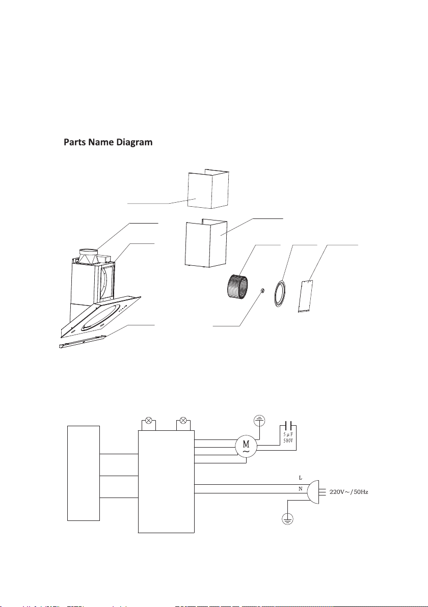
Parts Name Diagram .......................................................................................
Electrical Circuit Diagram ................................................................................
Main Technical Parameter .............................................................................
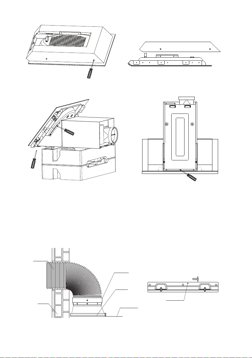
Installation Diagram..........................................................................................
Installation Steps.............................................................................................
Safety Instructions...........................................................................................
Oprating Instructions........................................................................................
Detachable Parts..............................................................................................
Troubleshooting................................................................................................
1
1
1
2
2
3
5
5
6
7
1
Accessories & Packing List
Electrical Circuit Diagram
1. Range Hood x 1 unit
2. User Instructions manual x 1 pc
3. Flow Exit x 1 pc
4. Flow Exit seal x 1 pc
5. Oil cllection container x 1 pc
6. Flexible exhaust duct x 1 pc
PCB
Red
Switch White
Black
Black
Brown
Brown
Blue
Orange
Green
wheel Cap
wheel Etrance Board Hood Cover
Extended Protection Tube
Protection Tube
Hood Flow Exit
Hood Box
Oil Cup
2
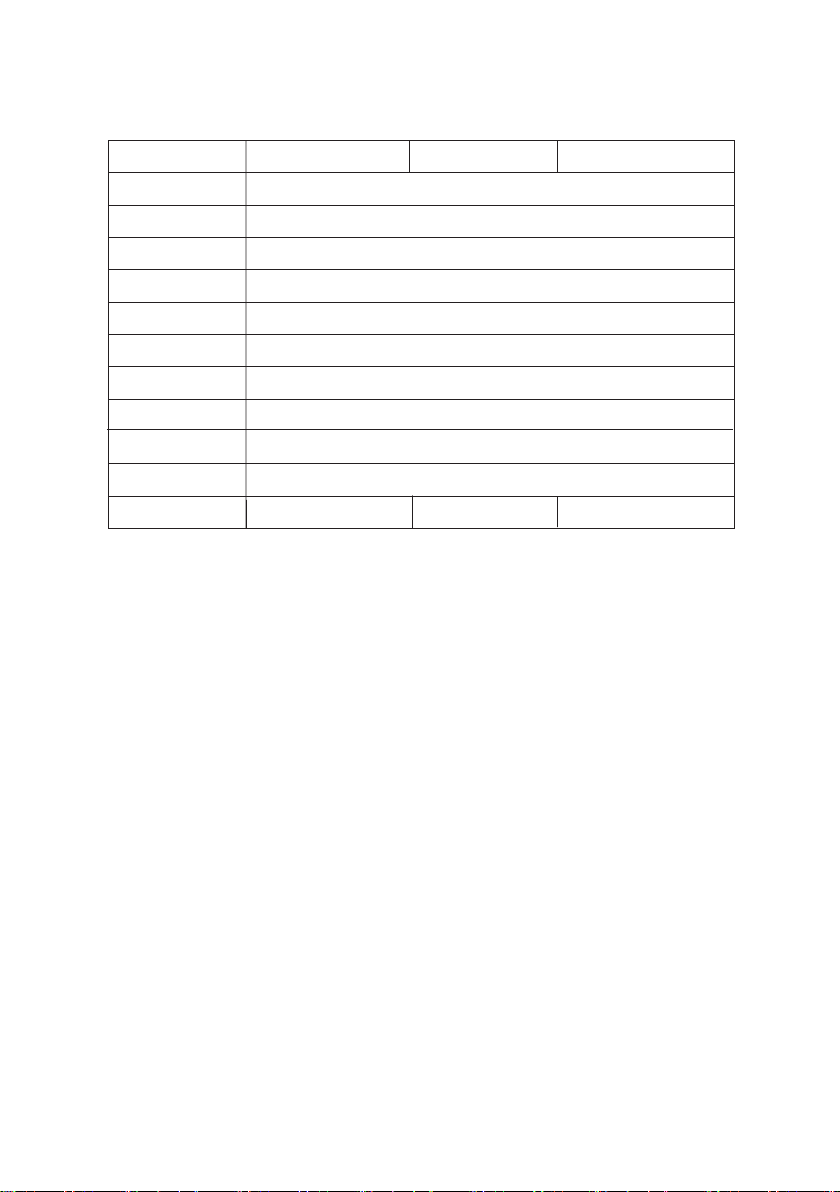
Model No
Rated Voltage
Rated Power
Max Airflow
Max Noise Level
Max Pressure
Wind pressure
Lighting
Motor Capacity
Tot.Absorption
Product Size
N.G
Main Technical Parameter
installation diagram
IMPORTANT:Installation must be carried out by our registered contractors.
1) Installation Height
Minimum height from the hob surface to the underside of range hood:
HA9055 HA9053 HA9052
220V~
50Hz
19m³/min)
54dB
≥390Pa
≥300Pa
≤4W
230W
234W
895X506X920(mm)
31kg 30kg 32kg
- 350 mm for electric hob
- 400 mm for gas hob
*If the instruction for the gas hob installation specified a greater distance, this has to be
taken into account
NOTE: Any installation above 700mm will compromise the performance of this range hood.
If the ceiling is low and hood is installed without extended chimney, there should be at least 3cm
gap between the ceiling and chimney.
2) Exhaust Duct
The length of the exhaust duct should be minimised to avoid air trubulence inside the duct

3
920
325
506
1260 1310
325
506
820
1260 1310
This product must be installed by our company's professional staff.
1.Slide the upper cover plate in the direction of arrow, remove the buckle piece and remove the
upper cover plate.
2.The internal bladder is assembled on the two side of the machine box with four M4 * 8 cross slot
large flat head self tapping screws to fix the inner liner, and the back is fixed with three M4 * 8 cross
slot large flat head self tapping screw.
3.It is shown that the control lead and lamp lead wire of the chassis are connected with the coil of
the protection coil respectively, and are respectively connected with the connector of the switch and
the lamp holder.
Punch position
Punch position
4
1. drill holes in the punching position of the picture, bury the plastic expansion pipe, and fix the hook
bar on the wall with 3 ST5 * 45 wood screws.
2. insert the end of the exhaust pipe out of the tuyere seat, fix the exhaust pipe on the side, take the
silver white tape on the exhaust pipe, and tear the bottom paper to the seams and seal it.
3. hang the main engine on the hook bar and extend the other end of the exhaust pipe outside. Or
access the public flue interface to seal it.
4. use a screw to fix on the hook bar to prevent the fume hood from falling off accidentally.
Hood Flow Exit
Seal Ring
Mounting Hole
Exhaust Duct
Range Hood
Wall
This manual suits for next models
2
Table of contents
Popular Ventilation Hood manuals by other brands

Gorenje
Gorenje S3 IHGC963S4X manual

KOBE
KOBE ISX2136SQB-1 Installation instructions and operation manual

U.S. Products
U.S. Products ADVANTAGE-100H Information & operating instructions

Kuppersberg
Kuppersberg DUDL 4 LX Technical Passport

Framtid
Framtid HW280 manual

Thermador
Thermador HGEW 36 FS installation manual


