decon JWB2 User manual

X0B-28197-000 BK DIC142p
X0E-28197-P1
Published September 2013
SERVICE MANUAL
This manual has been created as a guideline for maintenance
service to be performed at the dealers before and after the sale.
Please refer to it together with the Owner’s Manual.
For Electric Wheelchair, Electric Power Assist Unit for Wheelchairs
Nickel Metal Hydride Battery JWB2
Lithium Ion Battery ESB1
Nickel Metal Hydride Battery JWB2
Lithium Ion Battery ESB1
Nickel Metal Hydride Battery JWB2
Lithium Ion Battery ESB1
2020-06

Indicates correct methods and key points when operating the product.
Indicates that misuse may lead to fatal or severe injury, or disability.
CAUTION
Indicates that misuse may lead to material damage.
Foreword
This Service Manual describes the procedures for inspecting, adjusting and as well as how
to handle errors of the nickel metal hydride battery, lithium ion battery and battery chargers
for the electric wheelchair and the electric power assist unit for wheelchair manufactured by
Yamaha Motor.
Symbols Used in This Manual
Items concerning proper handling are indicated with the following symbols.
Other Precautions
• For product improvement purposes, the descriptions and specifications in this manual are subject
to change without notice.
• Due to changes in the specifications, some of the photos and descriptions may differ from the
actual product.
• This manual is intended for use by persons possessing the basic technical knowledge and skills.
• Persons who do not possess the general service skills and knowledge should not rely solely on
this service manual to perform inspection, adjustment, disassembly, or reassembly. Failure to
observe this precaution can lead to maintenance problems or mechanical damage.
WARNING
NOTE

CONTENTS
1. Nickel Metal Hydride Battery ..................4
1.1. Names of Parts and Circuits .......................4
1.2. Function of the Battery............................5
2. Lithium Ion Battery .........................10
2.1. Names of Parts and Circuits ......................10
2.2. Function of the Battery...........................11
3. Specications .............................15
3.1. Nickel Metal Hydride Battery Charger (JWC-2) ........15
3.2. Charger for Lithium Ion (ESC1) ....................20
3.3. Charger for Lithium Ion and Nickel Metal Hydride . . . . . . . .
Battery (ESC3).................................26
4. Specications .............................30
4.1. Specications..................................30

4
1
1. Nickel Metal Hydride Battery
1.1. Names of Parts and Circuits
Protective cap
Battery management system
Battery management controller
Thermistor
Temperature
fuse
White
Narrow
Red
Narrow
Blue
Narrow
Black Narrow
Black
Narrow
Black
Black
Sticker
Battery
management
system
Battery unit
TX RX -+
Internal wiring diagram
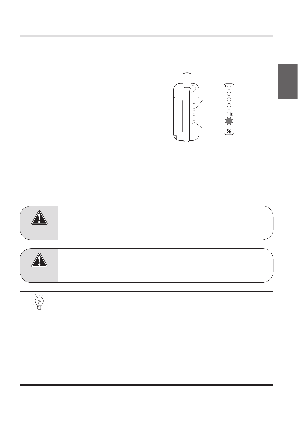
Indicator switch Capacity indicator lamp
Release button
Battery fuse
(20A blade type)
Screw
Contacts
20A fuse
Backup battery fuse
5
1
1.2. Function of the Battery
The battery management system, which is built-in the battery, provides the following three major
functions: “residual capacity management”, “battery information communication”, and “service”.
(1) Residual Capacity Management
The battery management system uses an “amperage
integration system” to manage the residual capacity,
and a “capacity learning system” to monitor the state
of deterioration of the battery in the form of capacity.
The indicator lamps located on top of the battery
indicate the residual capacity in 6 stages.
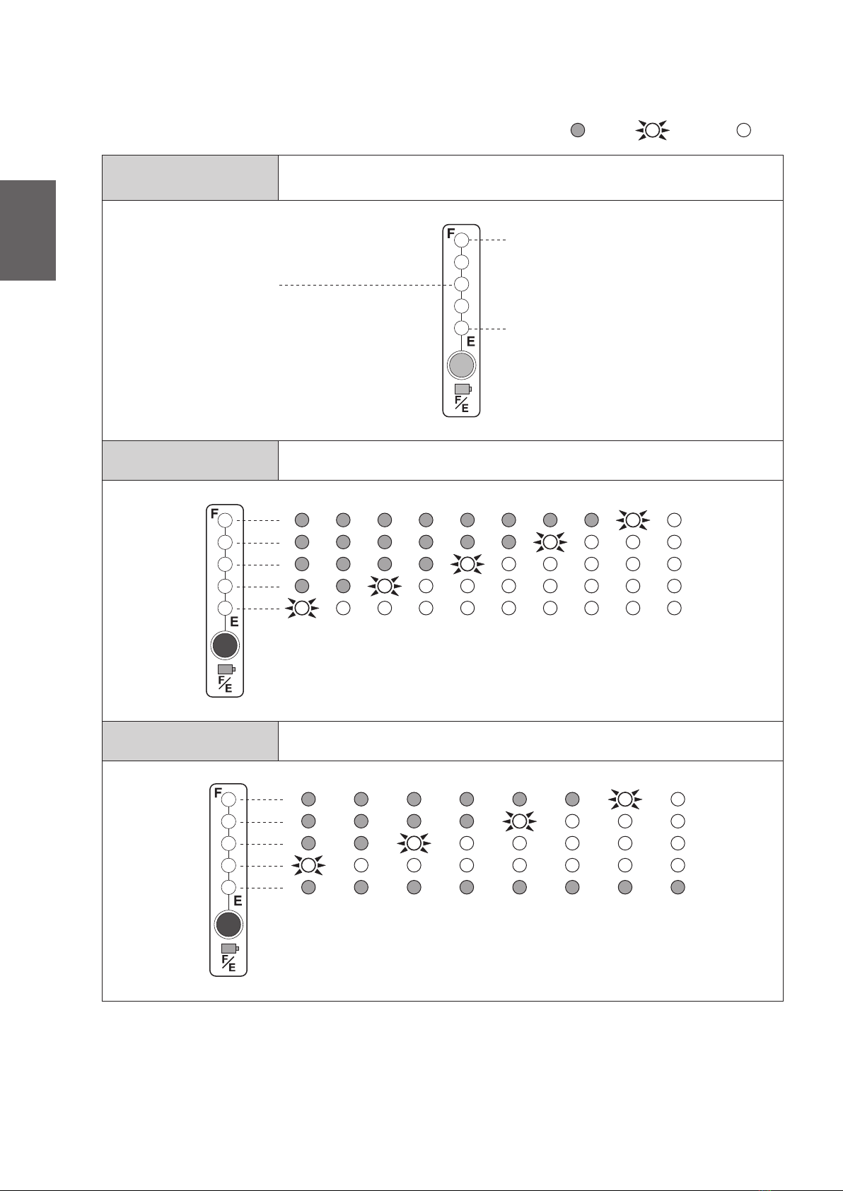
Residual Charge Indication
When the indicator switch is pressed, the 5
indicator lamps turn ON for 5 seconds to show the residual capacity of the battery in 6 stages.
(The last segment consists of 2 stages, ON and blinking.)
Battery Deterioration Indication
When the battery deteriorates below 80% of the initial capacity, the topmost segment of the
indicator will no longer turn ON after the battery is charged. As the battery deteriorates further
and its capacity decreases below 60%, the fourth segment will also stop turning ON.
CAUTION
If the capacity gauge shows that the battery has deteriorated prematurely,
perform a simple diagnosis in the service mode, which will be described later.
CAUTION
If 1 segment of the capacity gauge blinks (residual capacity warning), instruct
the user to immediately charge the battery or replace it with a spare battery.
• After the battery deteriorates, the residual capacity gauge might not fully turn
ON even after the battery is charged.
• At times, the battery might recover after the capacity gauge had shown the
battery to be deteriorated. This occurs when the battery becomes more active
due to the ambient temperature or the use mode.
• If the battery deteriorates below 60%, its charge-discharge characteristics
become unstable. Then, the battery capacity indicator will be unable to
accurately indicate the residual capacity. In this case, recommend that the
user replace the battery.
• The residual capacity gauge will be reset to 0 if the fuse is blown or removed.
It will revert to the normal indication after the battery is charged.
NOTE
Capacity
indicator
lamp
Indicator
switch
80–100%
40–60%
0–20%
20–40%
60–80%
(Blinks at 0 to 10%)
Capacity guide
(new state)

6
1(2) Battery Information Communication
The battery management system is equipped with a function to display and communicate various
information about the battery.
Battery Information Communication
The battery management system has a built-in function to establish communication with the
drive unit and the charger. It exchanges various types of information during charging and
discharging processes.
Out of Guaranteed Temperature Range Indication ·
Malfunction Diagnosis Indication
1. If the battery temperature gets below -5°C, the
capacity gauge will be unable to indicate the
precise capacity. Therefore, the capacity gauge
will blink to inform you that the battery tem-
perature is beyond the guaranteed temperature
range.
2. If the temperature sensor that is built into the
battery fails, the fourth LED will blink.
3. If the temperature of the battery becomes
abnormally high, the LEDs 1, 3, and 5 will blink.
CAUTION
If the battery will not be used for a long time, store it in a dry area, at a
temperature between 0 and 30°C. In addition, charge at least once every three
months.
Both the charger and the vehicle will show a communication malfunction if
communication is disabled due to the deformation of the contact points or the
entry of foreign matter.
NOTE

7
1
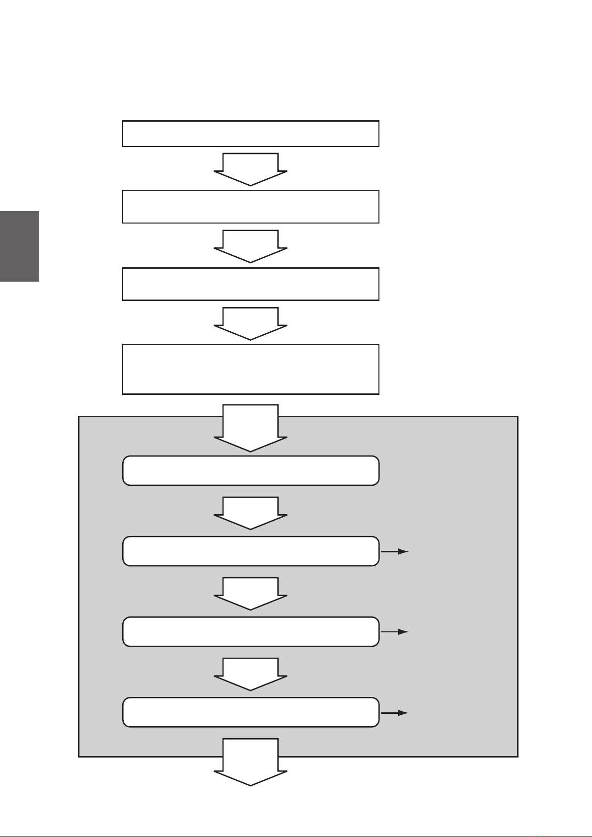
(3) Simple Diagnosis of the Battery (Service Mode)
On the battery, the battery management system has a service mode. This mode enables you to
perform a simple diagnosis on the battery as follows.
Push and hold the indicator switch for 10 seconds
The capacity indication will turn ON again
Then release the switch
The capacity indication will turn OFF in 5 seconds
Keep on pushing the switch
Service Mode
Shows all LEDs turned ON (LED check)
Any of the 5 LEDs turn ON
3 seconds
later
Shows a combination of LEDs that turn ON and blinking
30 seconds
later
Simple Battery
Diagnosis Table
Deterioration Level
Indication
30 seconds
later
30 seconds
later
Shows a combination of LEDs that turn ON and blinking
Reference Item
Use Frequency
Indication
Service mode ends
Before the capacity indication turns OFF (in almost 8
seconds), press the indicator switch twice.
The indications change after the number of
seconds shown below elapse or when the
indicator switch is pressed.
8
1
Simple Battery
Diagnosis Table
Deterioration Level
Indication
Use Frequency
Indication
This indicates the number of times the battery is used. A single
charging and discharging cycle constitutes 1 time.
Center LED is ON
Bottom LED is ON
Top LED is ON
The battery is normal.
Below
60%
60–
65%
65–
70%
70–
75%
75–
80%
80–
85%
85–
90%
90–
95%
95–
100%
100%
0–
99
100–
149
150–
199
200–
249
250–
299
300–
349
350–
399
Over
400
ON
OFF Blinking
* Indication of the deterioration level may not be correct, in case the refresh charging has not been performed
appropriately.
This indicates the deteriorated state of the battery in terms of
the ratio to the capacity of a new battery.
Refresh charge has not been performed,
or the capacity learn failed.
Advise the customer to be sure to perform
refresh charging the next time a refresh
notification is displayed on the charger.
Tester diagnosis is required.
Perform a complete diagnosis with
a battery tester.
Simple Diagnosis List

9
1
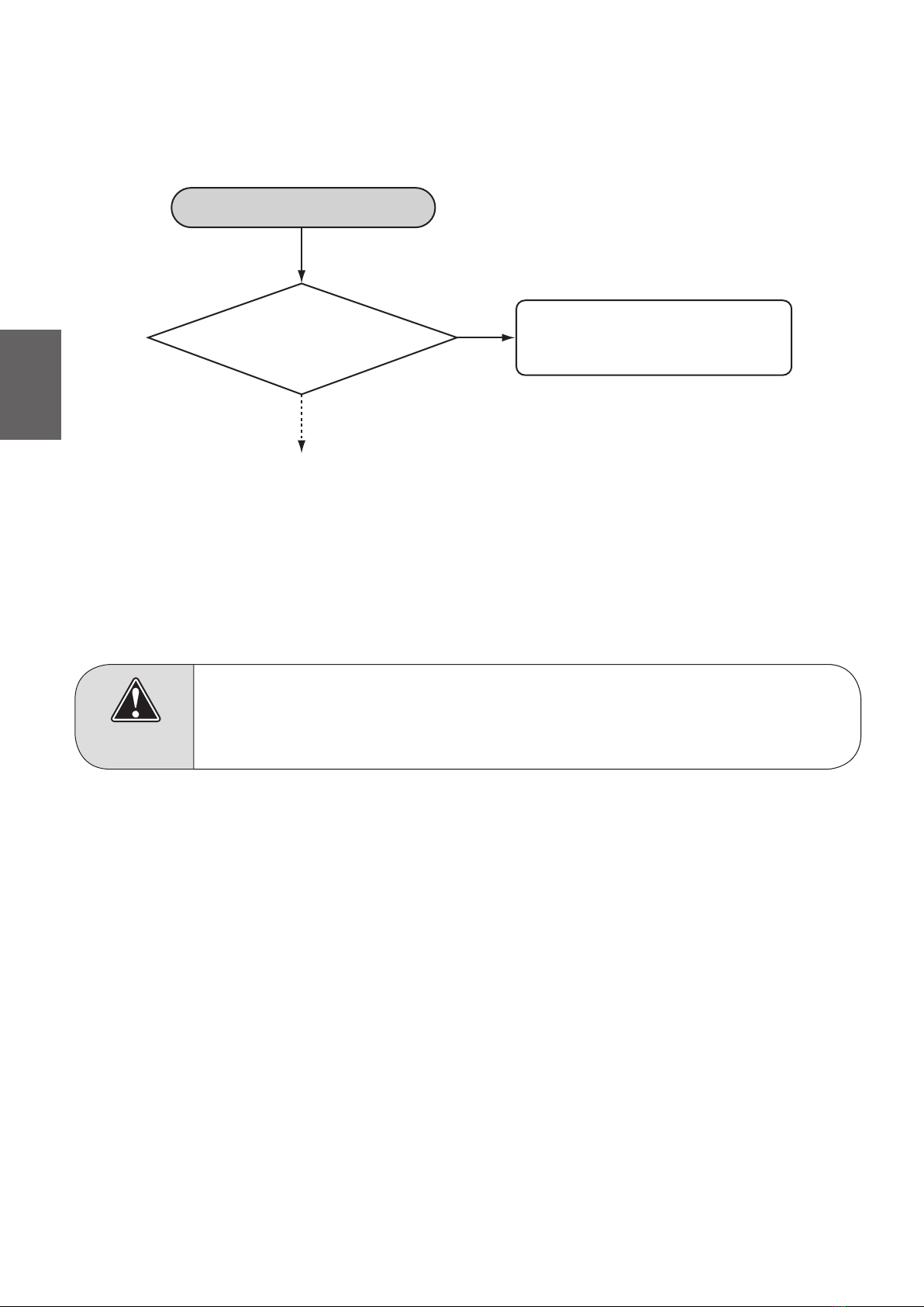
Start diagnosis
Is the battery fuse blown?
Has the battery voltage
dropped below 20V?
Does the switch on the
board operate when it is
pushed directly?
Is there an open circuit,
or a failed or detached
connector?
The battery management system
may have failed. Contact a person in
charge of service.
Eliminate cause of the blown fuse,
then replace the fuse.
Charge the battery.
The indicator switch is broken.
Repair the open circuit of the board
lead wire, or the failed or detached
connector.
Disassemble the battery case
Yes
No
No
Yes
No
Yes
No
Yes
(4) Troubleshooting the Battery Management System
If the battery management system cannot show the capacity or is unable to charge, diagnose the
systembyreferringtotheowchartbelow.

10
2
LED
TX RX
Battery management system
Battery management controller
Connector cover
Connector for charger
Manufactured date
(underside)
Protective cap
Capacity indicator lampIndicator switch
Gripping handle
Contacts
2. Lithium Ion Battery
2.1. Names of Parts and Circuits

11
2
2.2. Function of the Battery
The battery management system, which is built-in the battery, provides the following three major
functions: “residual capacity management”, “battery information communication”, and “service”.
(1) Residual Capacity Management
The battery management system uses an “amperage
integration system” to manage the residual capacity,
and displays the residual capacity in 6 stages using
the indicator lamps located at the top of the battery.
When the indicator switch is pressed, the 5 capacity
indicator lamps turn ON for 5 seconds to show the
residual capacity of the battery in 6 stages. (The last
segment consists of 2 stages, ON and blinking.)
For the lithium ion battery, a relative indication system is used, in which all 5 capacity indicator
lamps turn ON at the completion of a full charge cycle, even if the battery has deteriorated.
(2) Battery Information Management
Battery Information Communication
The battery management system has a built-in function to establish communication with
the drive unit and the charger, and exchanges various types of information while using the
wheelchair or during a charge cycle.
Battery Life Management
The battery management system of the lithium ion battery remembers its cumulative usage
time and integral charge capacity. In order to use the battery safely, the battery has an
upper limit (life) for the cumulative usage time and the integral charge capacity: 8 years and
8000Ah, respectively. Once you reach the upper limit (i.e. end of life), the BMC prevents
further charging or use of the battery.
CAUTION
If 1 segment of the capacity gauge blinks (residual capacity warning), instruct
the user to immediately charge the battery or replace it with a spare battery.
Both the charger and the vehicle will show a communication malfunction if
communication is disabled due to the deformation of the contact points or the
entry of foreign matter. In this case, clean the contact.
NOTE
Residual capacity
80–100%
40–60%
0–20%
20–40%
60–80%
(Blinks at 0 to 5%)
12
2
(3) Simple Diagnosis of the Battery (Service Mode)
On the battery, the battery management system has a service mode. This mode enables you to
perform a simple diagnosis on the battery as follows.
Release your hand from the indicator switch, and
press it again twice, before the capacity indicator turns
OFF.
Push and hold the indicator switch for 10 seconds
The capacity indication will turn ON again
Then release the switch
The capacity indication will turn OFF in 5 seconds
Keep on pushing the switch
Service Mode The indications change after the number of
seconds shown below elapse or when the
indicator switch is pressed.
Shows all LEDs turned ON (LED check)
Any of the 5 LEDs turn ON
3 seconds
later
Shows a combination of LEDs that turn ON and blinking
30 seconds
later
Simple Battery
Diagnosis Table
Deterioration Level
Indication
(absolute indication)
30 seconds
later
30 seconds
later
Shows a combination of LEDs that turn ON and blinking
Reference Item
Use Frequency
Indication
Service mode ends

13
2
Simple Battery
Diagnosis Table
Deterioration Level
Indication
This indicates the deteriorated state of the battery in terms of the ratio
to the capacity of a new battery.
Use Frequency
Indication
This indicates the number of times the battery is used. A single
charging and discharging cycle constitutes 1 time.
: OFF : ON : blinking (2 second interval)
: OFF : ON : blinking (2 second interval)
: OFF : ON : blinking (2 second interval) : blink (0.2 second interval)
Normal Charge
current
error
Thermistor
error
High
temperature
error
Battery
voltage
error
Measurement
mismatch
error
Low
temperature
regenerative
overcharge
1%–8% 9%–19% 20%–39% 40%–59% 60%–79% 80%–100%
0–49
times
50–99
times
100–149
times
150–199
times
200–249
times
250–299
times
300–349
times
350–399
times
400–449
times
450–499
times
500–549
times
over 550
times
Simple Diagnosis List
14
2
Start diagnosis
Has the battery voltage
dropped below 20V?
Charge the battery.
Yes
No
The battery management system
may have failed. Contact a person
in charge of service.
(4) Troubleshooting the Battery Management System
If the battery management system cannot show the capacity or is unable to charge, diagnose the
systembyreferringtotheowchartbelow.
(5) Battery Storage Method
To store the battery, charge it until 3 residual capacity lamps turn ON (which will charge the
battery about 50%). Then, store it in a dry place at a temperature between 10 and 25°C.
(6) State of Charge During Shipment and Storage Period
The charge capacity at the time of shipping from the factory has been adjusted to 25 to 30% of its
full capacity. To reduce electricity consumption during the transport, the residual capacity indicator
showazerocapacity,regardlessofthetruestateofchargecapacity,untiltherstchargecycle.
Pleasechargethebatteryattheretailstoreatthetimeofhand-otothecustomer.
CAUTION
• Never store a discharged or full battery in a place where the temperature
may become high. This will accelerate the deterioration of the battery.
• The battery will deteriorate gradually even if it is not used.
15
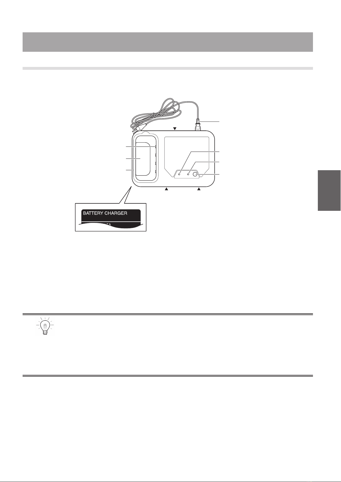
3
Contacts (4 locations)
Battery insertion opening
Gripping handle
Intake ventIntake vent
AC cable (releasable)
Exhaust vent
Refresh switch
Charge lamp
Refresh lamp
Type: JWC-2
The label on the reverse
side shows the model
(JWC-2)..
3.1. Nickel Metal Hydride Battery Charger (JWC-2)
The names and functions of the Nickel Metal Hydride Battery Charger (JWC-2) are explained below.
(1) Charging System
Pre-Charging
Starts charging at low amperage if the battery voltage is abnormally low.
Quick Charging
Charges an empty battery in approximately 2.5 to 3 hours.
Refrech Charging
Refresh charging a fully charged battery takes approximately 13 to 15 hours.
(2) Refresh Function
With refresh charging, the charger discharges the battery completely before charging.
This restores battery performance by improving the internal activation of the battery. The
communication function that is built into the JWC-2 charger receives optimal refresh timing in the
form of data from the battery management system. Thus, this function informs the user of when
the battery should be refresh charged. The JWC-2 charger is designed not to refresh charge
unless the refresh lamp is blinking.
• A battery from the factory or a battery that has undergone a deep discharge
requires approximately 120 to 130% longer to charge.
• If a battery is post-charged because it was charged at a high temperature, the
post-charging for replenishment purposes could take as much as 1.5 hours
longer. Furthermore, the capacity indication during charging will take a longer
time to blink the topmost segment (fully charged).
NOTE
3. Specications

16
3
Negative
contact
Communication
contact
Positive
contact
(3) Battery Protection Function
The temperature of the battery during charging significantly affects the life of the battery.
Therefore, the charger controls the charging based on the battery temperature data that is sent by
the battery management system.
(4) Multiple Input Function
The JWC-2 charger supports the power input of
AC100-240V, 50/60 Hz. Thus, it can be used within
the above range anywhere in the world. However,
pleaseadviseyourcustomersthattheconguration
of the AC plug varies from country to country.
(5) Communication Function
The JWC-2 charger has a built-in communication
function to establish communication with the battery.
The communication data passes through 2 contact
points. If there is a malfunction in the communication
contact points, the charger will be unable to charge.
Then, it will inform the user by indicating the
malfunction. (Refer to the Malfunction Indication,
which will be described later.)
The timing in which the refresh lamp blinks varies with the way in which the
battery is used. It blinks after the battery is used approximately 10 to 30 cycles.
Refresh charging a fully charged battery takes approximately 13 to 15 hours.
Therefore, recommend that the user refresh charge a battery from a state of
low residual capacity, whenever possible. When it is needed to skip the refresh
charge even the refresh lamp blinks, simply wait 1 (one) minute without pushing
the refresh switch, then the normal charge starts automatically.
NOTE
• The temperature of the battery at which the charger can start charging is
between 0 and 40°C.
• The charger will abort charging when the battery temperature reaches 50°C.
NOTE
The battery cannot be charged if the contact is deformed or dirty. If the contact
of the battery or the charger is dirty, wipe it with a dry cloth before usage.
NOTE

17
3
(7) Malfunction Diagnosis Function
Malfunction Location State of Indicator Lamp Required Action
Battery Malfunction
Green Yellow
Green and yellow blink
simultaneously.
• Replace the battery with a new one.
Communication Malfunction
Green and yellow blink
alternately.
• Replace the fuse with the spare.
• Clean or repair the contact points at the
battery and the charger.
• Replace the battery with a new one.
• Replace the charger with a new one.
Charger Malfunction 1
Blink in the sequence of
green, green and yellow.
• Replace the charger with a new one.
Charger Malfunction 2
(internal high temperature
malfunction)
Blink in the sequence of
green, green, green and
yellow.
• Replace the charger with a new one.
• Replace the cooling fan.
(6) Indication Function (List of Lamp Indications)
State Green Lamp Yellow Lamp
Pre-charging or temperature
standby Blinking OFF
Quick charging ON OFF
Charging completed OFF OFF
Refresh charging notice OFF Blinking
Refresh charging OFF ON
Malfunction indication Various types of blinking patterns (refer to the Malfunction Diagnosis Function)

18
3
Start diagnosis
Battery itself can
indicate its capacity
Contact points are
deformed or have foreign
matter on them
Is the amperage fuse
blown?
Eliminate the cause, and
then replace the fuse
Clean or repair
Charger is able to
charge a normal battery
Charger failure
Replace charger
Battery management
system failure inside
the battery
Proceed to the trouble-
shooting of the battery
management system
No
Yes
No
No
Yes
Yes
Yes
No
(8) Diagnosing Charger Communication Malfunction
If the charger is unable to charge due to a communication malfunction, perform a diagnosis by
referringtotheowchartbelow.

19
3
(9) Forced Refresh Charging
Ifyoumustperformarefreshchargingeventhoughtherefreshnoticationisnotdisplayed,such
as when there is an abnormal problem with the battery or the charger, you can perform a forced
refresh charging by following the steps below.
Press the display switch on the battery 4 times within 2 seconds.
Insert the battery in the charger.
The refresh lamp of the charger blinks.
While the refresh lamp of the charger is blinking, press the refresh switch.
This forced refresh charging may speed up the deterioration of the battery, or may damage it.
Therefore, forced refresh charging is not recommended unless it is necessary.
This function does not exist in the nickel metal hydride batteries manufactured before 3/13/2008
(manufactured lot: JWB2-83D).

20
3
Charger plug
AC cable
(releasable)
Gripping handle Indicator lamp
The model (ESC1) is
shown on the label on
reverse side.
3.2. Charger for Lithium Ion (ESC1)
The names and functions of the Lithium Ion Battery Charger (ESC1) are explained below.
(1) Charging System
Pre-Charging
Starts charging at low amperage if the battery voltage is abnormally low.
Quick Charging
Charges an empty battery in approximately 4.5 hours.
• On the first charge cycle after shipping from the factory, or when charging
after a deep discharge, it will take 1.2 to 1.3 times longer than normal to charge
the battery.
• If a battery is post-charged because it was charged at a high temperature, the
post-charging for replenishment purposes could take as much as 1.5 hours
longer. Furthermore, the capacity indication during charging will take a longer
time to blink the topmost segment (fully charged).
• In addition, the charging time varies depending on the ambient temperature,
the residual capacity of the battery, and the driving conditions of the
wheelchair before charging.
NOTE
If you notice an abnormality during charging, immediately abort charging,
unplug the AC cable, and pull out the charger plug from the battery.
WARNING
This manual suits for next models
1
Table of contents
Other decon Camera Accessories manuals


