DeDietrich DED700X User manual

December 2007 Edition Rev. 00
Service Manual
The manufacturer declines any responsibility or errors or omissions in this document. No part of the product can be reproduced, used
or copied without prior express written consent or unless this is allowed by a contractual clause.
Coffe machine
DE DIETRICH
DED700X

2
CONTENTS OF THE DE DIETRICH MAINTENANCE MANUAL
1. Introduction Rev 00 from page 3 to page 4
1.1 Appropriate documents
1.2 Tools and equipment
1.3 Safety instructions
2. Technical information Rev 00 from page 5 to page 7
2.1 Internal components
2.2 Product technical data
3. Programming diagnostics and tests Rev 00 from page 8 to page 16
3.1 Programming by the user
3.2 Diagnostics mode
3.3 Test Mode
3.4 Checking micro-switches in Test Mode
3.5 Outages displayed on the screen
3.6 Checking micro-switches and sensors
4. Diagrams Rev 00 from page 17 to page 20
4.1 Cabling diagram
4.2 Hydraulics diagram
5. Operating logic Rev 00 from page 21 to page 26
5.1 Hydraulic operating diagram
5.2 The SBS system
5.3 Aqua Prima
5.4 Fitting and removing OETIKER clamps
6. Fitting and removing components Rev 00 from page 27 to page 41
6.1 Removing the upper panel and component support frame
6.2 Removing the coffee grinder
6.3 Removing the grinding wheels
6.4 Removing the coffee grinder motor
6.5 Removing the boilers
6.6 Replacing the geared motor
7. Exploded views Rev 00 from page 42 to page 47
7.1 Exploded views
7.2 List of recommended spare parts (Check the part numbers with the latest exploded view)
8. Problems - Causes - Solutions Rev 00 from page 48 to page 49
8.1 Problems - Causes - Solutions

3
REV.00
CHAPTER 1
INTRODUCTION

4
1.1 Appropriate documents
In order to make repairs the following documents must be available:
Instruction notice specific to the model
Technical documents specific to the model (diagrams, exploded views)
1.2 Tools and equipment
The standard set of tools is needed plus the following special items :
1 special screwdriver with a T09 and T10 tip, Pozi Drive type screwdriver and a number 04 hex key.
1 Digital thermometer measuring range =200°C.
It should be usable for measuring liquids and surface temperatures.
1 pair of Oetiker clamp pliers
1 cutting pliers
1.3 Safety Instructions
It is recommended to read the machine’s instruction notice before carrying out any maintenance. Comply
to current standards for repair of household appliances.
Before beginning repairs on the machine, unplug it first. Turning the main power switch off is not
sufficient to avoid all risks of electrocution.
This appliance belongs to isolation class I. Once the repair has been made test its isolation and dielectric
strength.

5
REV.00
CHAPTER 2
TECHNICAL
INFORMATION

6
2.1 Internal components

7
2.2 Product technical data
Power supply and consumption 230 V~; 50 Hz; 1250 W
120 V; 60 Hz; 1250W
100 V; 60 Hz; 1250 W
Safety devices Coffee boiler 2 175°C safety thermostats – steam boiler 175°C
thermostat and 229°C heat fuse
Temperature control NTC Sensor
Coffee resistor Stainless steel heat exchanger - (1090W), for coffee or hot water.
Steam resistor Aluminium tube heat exchanger - (1000W) for steam production (high
speed steam production)
Pump Ulka vibration pump;
230V; 50 Hz; 48 W
120V; 60 Hz; 41 W
100V; 50/60 Hz; 55 W
Safety relief valve Safety pressure relief valve with compensation valve
Water filter Placed in the water tank
Coffee grinder (grinding wheel) Threaded brass spindle, ceramic grinding wheels
Motor DC 230 V / 120 V / 100 V
Absorption During temperature rise : approx. 4.8 A (230 V);
9 A (120V);
11 A (100V)
Absorption in energy-saving mode
(stand-by) Approx. 20 Watt/h
Main pump pressure 15 bar
Dimensions LxWxH (in mm) 595/325/458
Weight Approx. 16 kg
Coffee holder capacity (beans) Approx. 300 grams
Water tank capacity Approx. 2 litres at the maximum level
Heat exchanger volume Approx. 1.0 cm3(10 ml volume)
Water loading time Approx 10 seconds at start-up.
Temperature rise time Approx. 1.5 minutes.
Steam generation Immediate

8
REV.00
CHAPTER 3
PROGRAMMING
DIAGNOSTICS AND
TESTS

9
3.1 Programming by the user
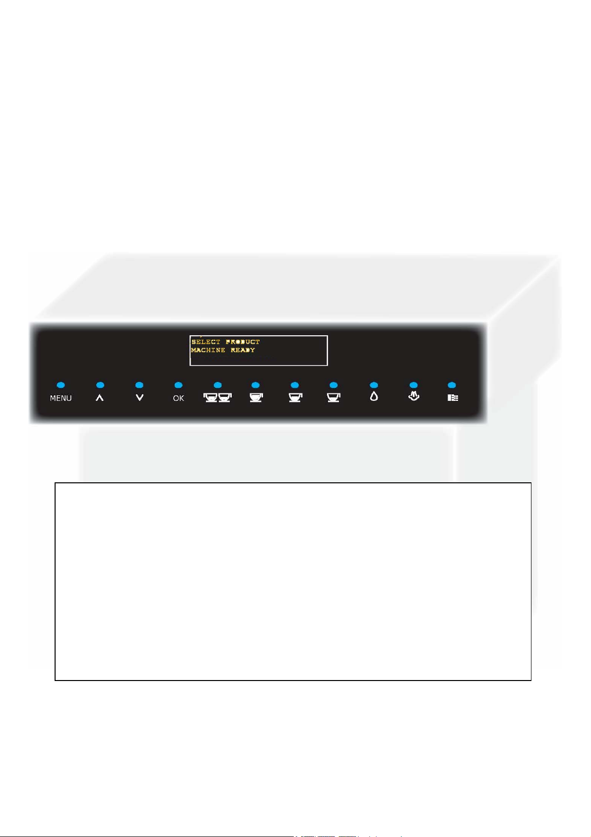
D On the main page press on the MENU key to access the
programming pages
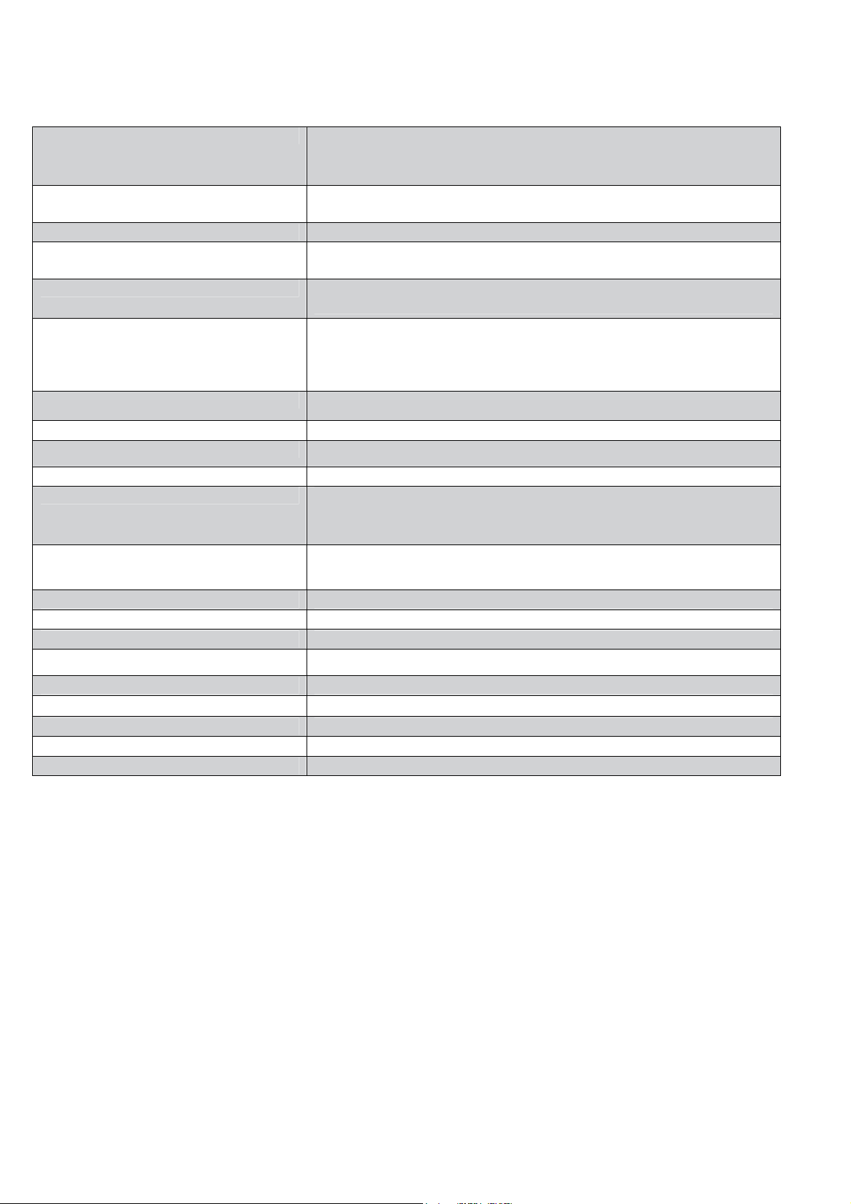
Press the OK key to go to ENERGY SAVING mode and reduce
power consumption. Press OK to restart the machine
The machine automatically eliminates water remaining in the
internal piping immediately after the heating phase so that only
fresh water is used to make the coffee
This function is used to choose the message display language.
This function is used to set the contrast in order to be able to
view the instructions clearly
The hardness of the water used to make the drinks varies from
region to region. This is why the machine should be set to the
correct degree of hardness for the water being used
This function is used to check the water filter (if one is used) by
warning the user when replacement is needed. The
“REINITIALISE” command should be used every time a new filter
is fitted.
This function is used to make warmer or hotter coffee by setting
water temperature (high, medium and low)
This function is used to set the dose of coffee (quantity) to grind
when making an expresso (strong, regular, weak)
This function is used to set the dose of coffee (quantity) to grind
when making a coffee (strong, regular, weak)
This function is used to set the dose of coffee (quantity) to grind
when making a large coffee (strong, regular, weak)
The pre-humidifer process increases the coffee aroma thus giving
the coffee an excellent taste. This function is used to humidify
the coffee before preparing it.
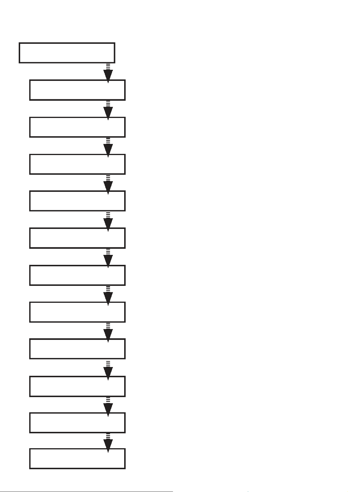
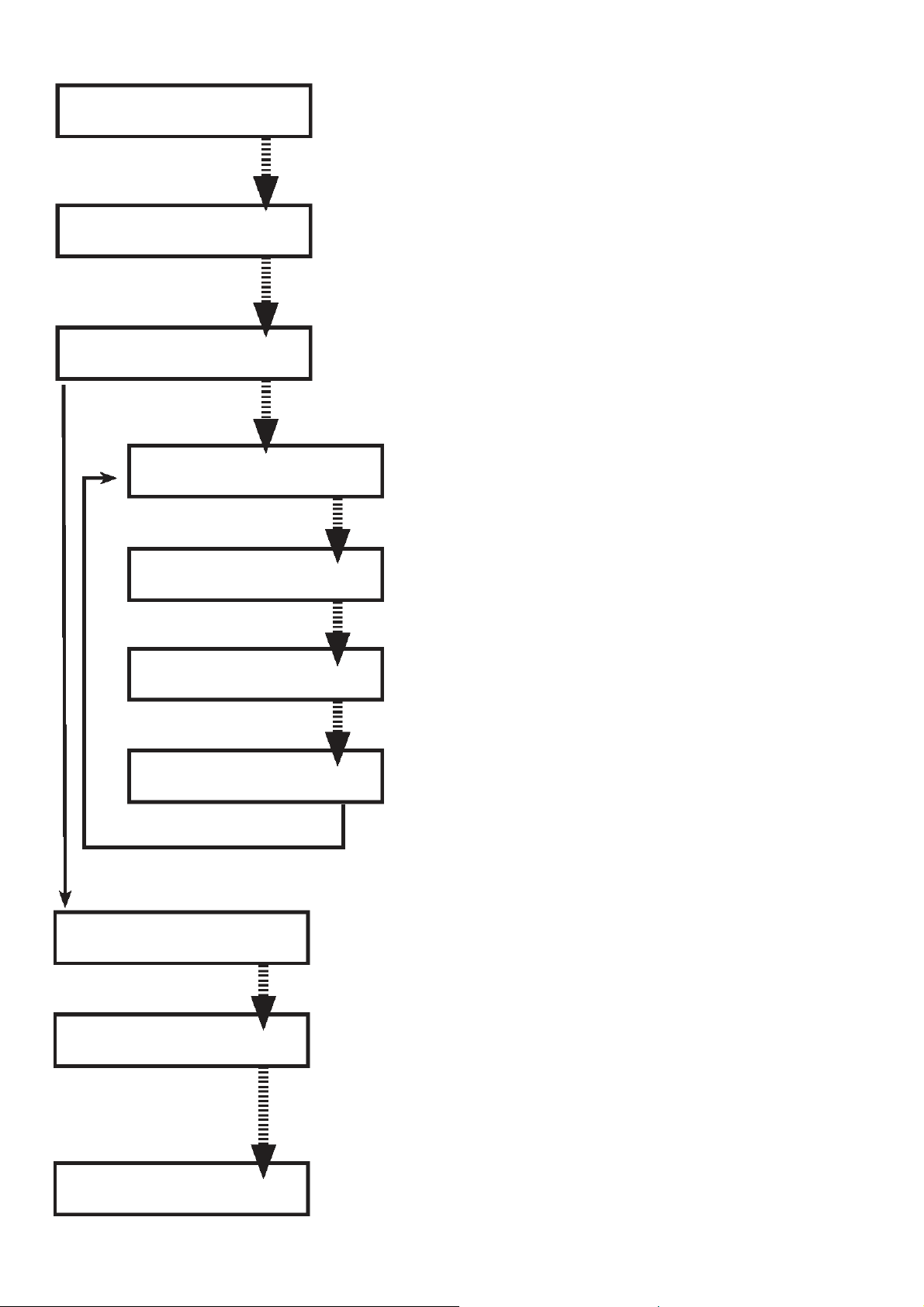
Select product
Machine ready
Energy savings À
Rince
Rince À
Language
Language À
Contrast
Contrast À
Water hardness
Water Hardness À
Water filter
Water filter À
Temperature
Temperature À
Expresso aroma
Expresso aroma À
Coffee aroma
Coffee aroma À
Large coffee aroma
Large coffee aroma À
Pre-humidifier
Pre-humidifier À
Total coffees

10
T
his function is used to display the total number of coffees made
by the machine
This function is used to save energy when the machine is not
used for long periods. This function is pre-set by the
manufacturer and automatically switches the machine to
ENERGY SAVING mode when the set time has passed.
This function that can be switched on and off by the user can be
used to :
- display the time when the machine is in “ENERGY SAVING” or
“SELECT FUNCTION” mode
- to select the machine start and stop times
Set the start and stop times
Set the current time
Set the start and stop times
Set time display
This function is used to carry out a washing cycle for parts used in
coffee distribution
This function is used to reset the default factory settings
Warning ! : custom settings are lost when resetting factory settings.
This function is used to quit the programming functions.
Total coffees À
Timer
Timer À
Clock
Clock À
Washing cycle
Clock À
Clock settings
Clock settings À
Time On/Off
Time On/Off À
Display Time.
Display Time À
Clock
Washing cycle À
Default settings
Default settings À
Quit
Quit
Energy savings

11
3.2 Diagnostics Mode
To go to “diagnostics mode” turn on the machine is displayed.
Within the first 5 seconds, press the 8-9-8-2 keys in order to display
and then press OK to display
The programming menu is displayed.
Keys “2” and “3” are used to scroll through the settings.
Key “4” is used to change the settings and confirm.
Key “1” is used to quit diagnostics mode.
MACHINE SETTINGS SETTING RANGE FUNCTION
1 1 Large coffee – 520 impulses 50 – 800 Number of pump impulses to make a large coffee
2 1 Expresso – 170 impulses 50 – 800 Number of pump impulses to make an expresso coffee
3 1 Coffee – 290 impulses 50 – 800 Number of pump impulses to make a coffee
4 Hot Water – 260 impulses 50 - 800 Number of pump impulses to distribute hot water
5 Steam timer 20 seconds 5 - 120
6 K1 Setting K1 Value 8 1 – 50 K1 is the temperature rise factor. High value = high factor (do
not modify the selected value)
7 K2 Setting K2 Value 30 1 – 50 K2 is the influence of frequency of use on the temperature
setting. High value = low influence (do not modify the selected
value)
8 Normal temperature 90 °C 70 – 130 °C Normal temperature
9 High temperature 110 °C 70 – 130 °C High temperature
10 Temperature of the 1st coffee
117 °C 70 – 130 °C Temperature of the first coffee
11 Total grounds 0 0 – 50 Coffee grounds counter
12 Stop grounds 12 0 - 50 Limit beyond which the coffee grounds tray should be emptied
13 Total water 0 Boiler 1 total distributed water (not modifiable)
14 De-scaling water ml -- 0 When the set value is reached the “de-scale” message is
displayed (not modifiable)
15 Water filter ml -- Quantity of water filtered since the Aqua Prima filter was
activated
16 H2O after de-scaling message
ml -- 0 Quantity of water used since the “de-scale” message was
displayed
17 Hot water flow l/h 20 06 - 26 Flow in l/h during hot water distribution
18 Hot water pump settings 62430 Pump settings for water distribution (do not modify the selected
value)
19 Water tank – number of
impulses 0 0 Water tank counter
20 Water tank stop – n° of impulses 750 Water tank stop
SELECT FUNCTION
MACHINE READY
Software
Programming
energy saving
Auto-diagnostic

12
21 Number of washing cycles 0 Washing cycle counter
22 Washing cycle status 0 Status of the washing cycle
23 De-scaling - Number 0 Number of de-scaling cycles
24 De-scaling status 0 De-scaling status
25 Phase code 128 Machine status indicator *
26 Last maintenance day 1 - 31 Last maintenance date (day)
27 Last maintenance month 1 - 12 Last maintenance date (month)
28 Last maintenance Year 2000- 2050 Last maintenance date (year)
* See table
Phase code description
BIT VALUE DESCRIPTION
0 1 Fill the machine (not enough water)
3 8 Start of coffee cycle. The distribution group is full of coffee
5 32 Machine waiting
7 128 Il BIT = 1 failure

13
3.3 Test Mode
Test mode is used to detect failures more easily and thus reduce the time needed to find them.
To enter TEST MODE
To go into “Test mode” switch on the machine, is displayed, within the next five seconds press
the 10-11-10-11 keys in order.
A series of letters and numbers will be displayed on the next page (see “Checking micro-switches in test mode”
table).
Anti-clockwise rotation of the geared motor Key 1
Check the anti-clockwise rotation of the geared motor and the rise of the coffee group. Check the noise made by the
geared motor.
When the geared motor is in distribution position the figure 1 should display on the top line.
Clockwise rotation of the geared motor Key 2
Check the clockwise rotation of the geared motor and the descent of the coffee group. Check the noise made by the
geared motor. When the geared motor is on standby the figure 2 should display on the top line.
Coffee grinder operation Key 3
Check the coffee grinder rotates anti-clockwise. Check the noise made by the coffee grinder.
(keep pressing until the grinder stops automatically). If the grinder motor is running, a reference value for the number of
revs. is shown (approx. 6-12) on the lower right side of the display and the figure 9 starts flashing on the top line.
Water – steam solenoid valve operation Key 3 + 7
Check that the pump is working correctly and check the noise it makes. During water distribution check that the turbine
is working correctly (the flow in litres/h is shown at the bottom right side of the display)
Water – steam solenoid valve operation Key 2 + 7
Check that the solenoid valve is working correctly
SELECT FUNCTION
MACHINE READY
Auto-diagnostic

14
Pressured up pump operation Key 1 + 7
To check that the pump is pressured up. (this is done to check for eventual leaks inside the machine)
Steam boiler electric current Key 4 + 6
Check the electric current using an ammeter.
During the temperature rise approx. :
4.8 A (230 V);
9 A (120V);
11 A (100V)
Coffee boiler electric current Key 2 + 6
Check the electric current using an ammeter.
Boiler temperature Key 4 + 6 + 7
This function is used to check the current temperature of the coffee boiler
Contrast LCD Key 1 + 6 + 7
Back-light LCD Key 2 + 6 + 7
3.4 Checking micro-switches in Test Mode
Display
N° Micro-switch Function
1 Geared motor in distribution
phase switch It sets the stopping point of the group’s rise
2 Geared motor on standby
switch It sets the stopping point of the group’s descent
3 Panel switch
5 Coffee ground tray and drip
tray switch Detects the presence of the coffee grounds tray and the drip tray
6 Coffee group switch Detects the presence of the coffee group
7 Door switch Detects the correct shutting of the door
8 Turbine sensor Counts the turbine impulsions in order to define the quantity of water to
be used when making the coffee
9 Coffee grinder sensor Defines the number of revolutions depending on the dose of coffee
0 Water sensor Detects when there is insufficient water in the tank
A Water tank safety sensor Detects when the water tank is full
M No Coffee Detects when there is no more coffee in the coffee holder
R RTC control Detects correct function of the clock (it should blink)
K Facade detector Detects the presence of the facade
0-8 Coffe grinder setting Detects the coffee grinder settings in factory control phase
* Coffee grinder impulses Indicates whether the value on the previous line (0-8) was saved

15
3.5 Outages displayed on the screen
DISPLAYED OUTAGES CAUSES/SOLUTIONS
GSI (water supply outage) -
- Internal drip tray sensor
Power
PURGE -
- Run water
Check the water tank is correctly installed
GROUP BLOCKED -
-
-
Replace upper / lower micro-switch
Power
Small geared motor
CLOSE THE PANEL
-
-
-
-
Close the front panel
Micro-switch
Earthing of the machine disrupts the micro-switch
Cut cables
CLOSE THE DOOR
-
-
-
-
-
Close the front panel
Micro-switch
TRB support unhooked
Door hinge bent
Cut cables
COFFEE GROUNDS TRAY MISSING -
-
-
Put the coffee grounds tray back
Micro-switch
Cut cables
GROUPE MISSING
-
-
-
-
Put the group back
Micro-switch
Group flange broken
Cut cables
NOT ENOUGH COFFEE -
-
-
Add coffee
Replace PW
Replace coffee griinder sensor
DESCALE -
- Descale
Replace CPU
GRINDER BLOCKED -
- Replace the coffee grinder
Replace PW
FILL WATER TANK -
-
-
Jammed floater
Replace water sensor
Replace PW
FLASHING DISPLAY -
-
-
Replace CPU
Replace PW
Crushed cables
WAIT (does not heat) heat LEDs off -
-
-
Reinitialise the thermostats
Boiler cable disconnected
Replace PW
PART OF THE DISPLAY MISSING OR
DISTORTED -
- Replace the display
Replace CPU
NO STEAM -
- Replace steam boiler
Replace PW

16
3.6 Checking micro-switches and sensors
N° Description Activated Deactivated Notes
1 Geared motor micro-
switch WORK Distributor in WORK
position Distributor not in
WORK position
2 Geared motor micro-
switch HOME Distributor in HOME
position Distributor not in
HOME position
3 Front command strip
micro-switch Command strip closed Command strip
open
5 COFFEE GROUNDS TRAY
micro-switch Tray present Tray absent
6 DISTRIBUTION GROUP
micro-switch Present Absent
7 DOOR Micro-switch Door closed Door open
8 FLOW METER
The technician
can check the
impulses
9 COFFEE GRINDER
IMPULSES
The technician
can check the
impulses
0 WATER LEVEL in the
tank Level is OK Level is LOW
A WATER ALARM micro-
switch Water detected in the
bottom of the machine No water detected
in the bottom of the
machine.
M Coffee holder empty There is no coffee There should be
coffee. This is derived
and not
hardware data.
R CLOCK (shows seconds) Even seconds Odd seconds It should flash at
1 HZ
K FRONT FACE PRESENT Present Absent
0-8 COFFEE GRINDER
SETTINGS
Factory settings
* COFFEE GRINDER
SETTINGS SAVED Not saved Saved

17
REV.00
CHAPTER 4
DIAGRAMS

18
4.1 Cabling diagram

19
Fuses
FUSE 120 V 230V DESCRIPTION
PF1 02A/250V 01A/250V Coffee grinder safety
PF2 16A/125V 08A/250V Coffee boiler, grinder, main circuit
and pump safety
PF3 16A/125V 08A/250V Steam boiler safety
PF4 02A/250V 02A/250V Main circuit safety

20
4.2 Hydraulics diagram
Table of contents
Other DeDietrich Coffee Maker manuals
Popular Coffee Maker manuals by other brands

Cimbali
Cimbali M2 Barsystem Description of the machine and of the control panel

TurboTronic
TurboTronic ZESPRESSO TT-CM23 instruction manual

S.V.ITALIA
S.V.ITALIA SAB SOPHIA user manual

Philips
Philips Senseo HD6556 manual

Proctor-Silex
Proctor-Silex 42114 user guide

Ariston
Ariston MCA 15 NA P - 39804 Instructions for use