Dehler 35 User manual

Name of Boat
Order Number
730-
Design Category
A
OWNER’S MANUAL
DEHLER 35
Dehler Yachts GmbH
Industriegebiet Im Langel 22
D-59872 Meschede-Freienohl
Tel.++49-(0)2903-440-0
Fax ++49-(0)2903-440-282

Yacht Manual DEHLER 35
2 - 63
Manual version 05.07.12
Your Distributor’s Stamp

Yacht Manual DEHLER 35
3 - 63
1.1 List ofcontents
1.1 LIST OF CONTENTS ..............................................................................................................................3
1.2 LIST OF ILLUSTRATIONS...........................................................................................................................5
1.3 INTRODUCTION........................................................................................................................................6
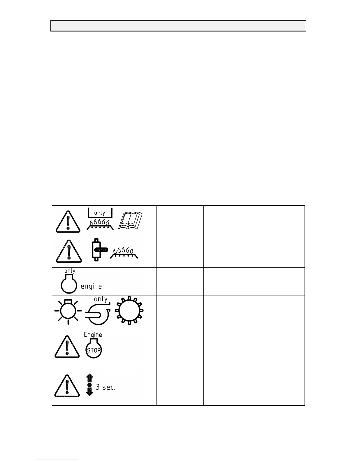
1.4 STICK ON NOTICES -LIST ........................................................................................................................7
1.5 DESIGN CATEGORY .................................................................................................................................9
1.6 IDENTIFICATION ......................................................................................................................................9
1.7 MANUFACTURER’S PLATE .....................................................................................................................10
1.8 STATEMENT OF CONFORMITY ................................................................................................................11
2. DESCRIPTION OF THE BOAT.............................................................................................................13
2.1 MAIN DATA........................................................................................................................................... 13
2.1.1 Load.............................................................................................................................................. 14
2.2 HEIGHT................................................................................................................................................. 14
2.3 TRANSPORT MEASUREMENTS.................................................................................................................15
2.4 MAXIMUM NUMBER OF PERSONS............................................................................................................15
2.5 LIFE-RAFT.............................................................................................................................................16
2.6 CRANES ................................................................................................................................................16
3. GENERAL DRAWINGS.........................................................................................................................17
3.1 2CABIN VERSION..................................................................................................................................17
3.2 DECK PLAN ........................................................................................................................................... 18
3.2.1 Deck..............................................................................................................................................19
3.2.2 Guard rails.................................................................................................................................... 19
3.3 SAIL PLAN.............................................................................................................................................19
3.3.1 Sail dimensions.............................................................................................................................. 19
3.3.2 Rigging plan..................................................................................................................................20
3.3.3 Halyard running............................................................................................................................20
3.3.4 Genoa slide / Main sheet traveller..................................................................................................21
3.4 SHROUDS,STAYS AND HALYARDS ..........................................................................................................21
3.4.2 Forestay with Furlex-system.......................................................................................................... 22
3.5 CALCULATING THE LENGTH OF THE FORESTAY WIRE...............................................................................23
3.6 CALCULATING THE LENGT OF THE LUFF EXTRUSION................................................................................ 24
3.7 SUMMARY OF HALYARD SIZES................................................................................................................25
4. DESCRIPTION OF INBOARD SYSTEMS............................................................................................26
4.1 ENGINE INSTALLATION ..........................................................................................................................26
4.1.1 Exhaust system .............................................................................................................................. 26
4.1.2 Propeller....................................................................................................................................... 27
4.1.3 Fuel tank.......................................................................................................................................28
4.1.4 Fuel supply/circulation.................................................................................................................. 28
4.1.5 Engine switch panel.......................................................................................................................29
4.1.6 Engine monitoring.........................................................................................................................29
4.1 FRESH WATER,DRINKING WATER ...........................................................................................................30
4.2.1 Cockpit shower..............................................................................................................................30
4.3 WASTE WATER PUMP.............................................................................................................................31
4.4 ALTERNATING CURRENT INSTALLATION .................................................................................................31
4.4.1 Shore connection unit .................................................................................................................... 31
4.4.2 Battery charger Sterling................................................................................................................. 32
4.5 ONBOARD DIRECT CURRENT SYSTEM......................................................................................................32
4.5.1 Master switches.............................................................................................................................32
4.5.2 Arrangement of main fuses.............................................................................................................33
4.5.3 Identifying the cables..................................................................................................................... 34
4.5.4 Additional fuses.............................................................................................................................35
4.5.5 Control panel data.........................................................................................................................35
4.5.6 Battery Charging...........................................................................................................................35
4.5.7 Auxiliary supply.............................................................................................................................36
4.5.9 Terminals/Supplies ........................................................................................................................ 36
4.5.10 General consumers......................................................................................................................33
4.5.11 Electric wiring diagram...............................................................................................................33

Yacht Manual DEHLER 35
4 - 63
4.6 BILGE SYSTEMS.....................................................................................................................................34
4.6.1 Anchor locker................................................................................................................................ 34
4.6.2 Cockpit..........................................................................................................................................34
4.6.3 Hand bilge pump ...........................................................................................................................34
4.6.4 Piston pump...................................................................................................................................35
4.6.5 Electric bilge pump........................................................................................................................ 35
4.7 RUDDER SYSTEM ...................................................................................................................................36
4.7.1 Wheel steering............................................................................................................................... 36
4.7.2 Rudder blade and rudder bearing...................................................................................................37
4.7.3 Emergency tiller............................................................................................................................ 37
4.8 GAS INSTALLATION ...............................................................................................................................38
4.8 PUMP -WC...........................................................................................................................................40
4.9.1 Rapid shut-off valves...................................................................................................................... 40
4.9.2 Holding tank.................................................................................................................................. 40
4.9.3 Holding tank indicator................................................................................................................... 41
4.9.4 Emptying of the tank...................................................................................................................... 41
5. FIRE PROTECTION ...............................................................................................................................42
5.1 FIRE PREVENTION .................................................................................................................................42
5.2 ACTIVE FIRE PROTECTION ...................................................................................................................... 43
5.3 FIREFIGHTING .......................................................................................................................................43
5.4 IN THE EVENT OF FIRE IN THE GALLEY ....................................................................................................44
5.5 IN THE EVENT OF FIRE IN THE ENGINE COMPARTMENT .............................................................................44
5.6 IN THE EVENT OF FIRE IN THE LIVING AREA .............................................................................................44
6 HEATING.................................................................................................................................................45
6.1 HOT AIR................................................................................................................................................45
6.2 DISPENSING PUMP/FILTER...................................................................................................................... 46
6.3 TEMPERATURE CONTROL .......................................................................................................................46
7 . HULLOPENINGS, SEA COCKS..........................................................................................................47
7.1 LEAK STOPPERS..................................................................................................................................... 48
8. ANCHORING, TOWING AND MOORING SYSTEMS........................................................................48
8.1 ANCHOR ...............................................................................................................................................48
8.2 SECOND ANCHOR...................................................................................................................................48
8.3 MOORING ROPES ...................................................................................................................................48
8.4 TOWING ROPE ....................................................................................................................................... 49
9. ENVIRONMENTAL PROTECTION.....................................................................................................49
9.1 FUEL AND OIL........................................................................................................................................ 49
9.2 RUBBISH ............................................................................................................................................... 49
9.3 NOISE ...................................................................................................................................................49
9.4 BACKWASH ........................................................................................................................................... 50
9.5 EXHAUST FUMES ...................................................................................................................................50
9.6 ANTIFOULING PAINT .............................................................................................................................50
9.7 PAINT REMOVER....................................................................................................................................50
9.8 HOLDING TANK .....................................................................................................................................50
10. TEN GOLDEN RULES FOR WATER SPORTSENTHUSIASTS.......................................................51
11. MAINTENANCE, REPAIRS AND CLEANING..................................................................................52
11.1 HULL,DECK ........................................................................................................................................ 52
11.2 CLEANING...........................................................................................................................................52
11.3 VENTILATION......................................................................................................................................52
11.4 RIGGING .............................................................................................................................................52
11.5 CARE OF THE SAILS .............................................................................................................................53
11.6 ENGINE AND PROPELLER......................................................................................................................54
11.6.1 Interval between engine servicing.................................................................................................54
11.6.2 Exhaust system /Maintenance.......................................................................................................54
11.7 ELECTRICITY.......................................................................................................................................54

Yacht Manual DEHLER 35
5 - 63
11.8 HOSE CLAMPS .....................................................................................................................................55
11.9 HEAT EXCHANGER...............................................................................................................................56
11.10 PUMP WC .........................................................................................................................................56
11.11 HOLDING TANK .................................................................................................................................56
11.12 PAINT................................................................................................................................................56
11.13 WORN AND SPARE PARTS ...................................................................................................................57
11.14 HULL OPENINGS.................................................................................................................................57
11.15 REPAIRS............................................................................................................................................57
12. WINTER STORAGE.............................................................................................................................57
13. FINAL REMARKS AND TIPS .............................................................................................................57
14. WARRANTY ......................................................................................................................................... 59
15. MANUFACTURERS’ INFORMATION...............................................................................................59
1.2 List of Illustrations
FIGURE 1: WARNINGS ..................................................................................................................................8
FIGURE 2: TRANSPORT MEASUREMENTS ..................................................................................................... 15
FIGURE 3: LIFTING POINTS FOR BELTS.........................................................................................................16
FIGURE 4: GENERAL ..................................................................................................................................17
FIGURE 5: DECK PLAN................................................................................................................................18
FIGURE 7: HALYARD RUNNING ...................................................................................................................20
FIGURE 8: SHROUDS STAYS........................................................................................................................21
FIGURE 9: FORESTAY WITH FURLEX-SYSTEM .............................................................................................. 22
FIGURE 10: ENGINE INSTALLATION............................................................................................................. 27
FIGURE 11: FUEL TANK .............................................................................................................................. 28
FIGURE 12: FUEL LINES.............................................................................................................................. 29
FIGURE 13: DRINKING WATER ....................................................................................................................30
FIGURE 14: SHORE CONNECTION PANEL......................................................................................................31
FIGURE 15: MASTER SWITCHES ENGINE ...................................................................................................... 32
FIGURE 17: MAIN FUSES.............................................................................................................................33
FIGURE 18: CONTROL PANEL WITH CONNECTION NUMBERS ......................................................................... 34
FIGURE 19: TERMINALS .............................................................................................................................36
FIGURE 20: BILGE SYSTEM .........................................................................................................................34
FIGURE 21: WHEEL STEERING ....................................................................................................................36
FIGURE 22: EMERGENCY HEAD...................................................................................................................37
FIGURE 23: GAS INSTALLATION.................................................................................................................. 38
FIGURE 24: GAS SHUT-OFF VALVE ..............................................................................................................39
FIGURE 25: RAPID SHUT OFF VALVESHOWERROOM ....................................................................................40
FIGURE 26: HOLDING TANK SYSTEM...........................................................................................................41
FIGURE 27: FIRE EXTINGUISHERS................................................................................................................43
FIGURE 28: HOT AIR .................................................................................................................................. 45
FIGURE 29: HULL OPENINGS.......................................................................................................................47

Yacht Manual DEHLER 35
6 - 63
1.3 Introduction
This manual has been written and compiled to make it possible
for you to use your sailing yacht, a DEHLER 35, in a safe and
pleasant way.
Apart from many details regarding the yacht itself, the manual
also contains details about the equipment supplied or integrated
fittings and information on its use and maintenance, in addition
to the information given by the manufacturer. Please read the
manual through carefully and get familiar with everything before
you go sailing with your yacht.
We recommend that you make copies of the important parts of
the manual and of some of the manufacturer’s information, such
as instructions about maintenance and warnings, so as to have
them handy on board in case you need to find out the cause of a
technical fault quickly and remedy it.
We hope you will enjoy your new DEHLER 35 and wish you
good luck and safe sailing.
An owner’s manual however can never replace the knowledge of seamanship which is
necessary.
An Owner’s Manual is a technical document which gives you a general description of the
yacht and its technical systems. It helps the skipper/sailor to handle and maintain the yacht
and its systems safely, identify possible technical faults and sometimes even to rectify these
faults himself. Furthermore it is to the advantage of the owner to undertake maintenance and
servicing of the Dehler 35 and thus maintain its value. Maintenance should only be done by
experienced people. Changes which are done after delivery of the boat without any notice and
confirmation by the yard are out of responsibility of the yard.
The shipyard reserves the right to carry out changes in equipment and technique. The systems
represented in this manual should not be considered as a basis for the sales contract. In this
respect you should use the construction specifications and the relevant price list for the
purchase of your yacht.
PLEASE KEEP THIS MANUAL IN A SAFE PLACE AND GIVE IT TO THE
NEW OWNER, IF YOU SELL THE YACHT.

Yacht Manual DEHLER 35
7 - 63
This owner’s manual is not a course on boating safety or seamanship. If this is your first craft,
or if you are changing to a type of craft you are not familiar with, for your own comfort and
safety, please ensure that you obtain handling an operating experience before “assuming
command” of the craft. Your dealer or national sailing federation or yacht club will be advise
you of local sea schools, or competent instructors. Ensure that the anticipated wind and sea
conditions will correspond to the design category of your craft, and that you and your crew
are able to handle the craft in these conditions. Even when your boat is categorized fro them,
the sea and wind conditions corresponding to the design categories A, B and C range from
severe storm conditions for category A, ti strong conditions for the top of the category C,
open to the hazards of a freak wave or gust. These are therefore dangerous conditions, where
only a competent, fit and trained crew using a well maintained craft can satisfactorily operate.
This owner’s manual is not a detailed maintenance or trouble-shooting guide. In the case of
difficulty, refer to the boat builder or his representative. If a maintenance manual is provided,
use it for the craft’s maintenance.
1.4 Stick on notices - List
List of the most important information, indicated by stick on notices.
Observance of the notices is very important for both the boat and its crew. Non-observance
of the notices can lead to total loss of the boat and problems for the crew. As the skipper
responsible for the boat’s safety you should inform new crew members about the notices and
their meaning.
Don’t use the
cooker for heating!
Notice on front trim of the cooker lid
Shut off valve
Gas
Oven
Notice on the locker flap in the stern cabin
port side
Main switch
Engine
Notice next to the switch on the engine
bulkhead forward in the stern cabin
Main switch
General
consumption
Notice next to the switch u-sofa salon
Emergency shut-
off
valve
Fuel
Diesel engine
Sticker base of wetcell locker
Only switch with
neutral number of
revolutions!
Sticker next to the Gas/Switch

Yacht Manual DEHLER 35
8 - 63
Cold-resistant
Please observe
manufacturer’s
instructions!
Switch at navi place for boiler
and head below cover WC
Fuse
12V
A= see print
Sticker in space U-sofa port side
Automatic fuse
110V or 230V
Sticker next to the automatic fuse
Shore connection in cockpitlocker
star bord
Sticker
Fire extinguisher
Notice for fire extinguisher under navigation
seat and under the aft locker starboard
Sticker switch
pump shower
Sticker in fornt of head
When sailing, close
the sea cocks
Sticker on bulkhead storage stern,
door wetcell locker,
floorboard in front of head, galley door
below sinks
Notice for the
escape hatch
Sticker on frame of escape hatch forward
Lifting belt
position
Four stickers on deck side
Gas Installation
Warnings
Sticker at the bulkhead for the gas bottle
Notice for
operating pressure
of gazsystem
Sticker in gazbox
FIGURE 1: WARNINGS

Yacht Manual DEHLER 35
9 - 63
1.5 Design Category
One of the requirements of the EC Directive on Pleasure Craft is that every boat must belong
to a specific design category.
The yacht type DEHLER 35 belongs to Design Category A.
The Directive describes Design Category A as follows:
Design Category A: High Sea
Designed for longer trips, with possible weather conditions of a force 8 wind or above
(Beaufort Scale) and waves 1) as high as 4 m or more, these boats can continue sailing on
their own. Abnormal conditions such as hurricanes are excluded. Such conditions may be
encountered on extended voyages, for example across oceans, or inshore when unsheltered
from the wind and wave for several hundred nautical miles.
1.6 Identification
For a yacht of this size the EC Directive only provides for B module certification. This means
that the manufacturer certifies the conformity of its construction and equipment with the
directive, but that its stability needs to be tested by a recognised testing institute. The ECB
Niederlande one of the testing institutes authorised by the EC Directive, was in charge of
testing; see the Statement of Conformity on page 12.
The hull identification number was stamped in the gel coat on the surface of the starboard side
of the boat. This is a worldwide unique succession of numbers and letters. For example:
DE-DEH 73011K909
This succession of numbers and letters comprises the following data:
DE Germany, Country of Origin
DEH Unique Shipyard Code
(the Register is kept by the German Boat and Shipbuilders’ Association)
73 Designated Type as chosen by the shipyard
11 Serial Construction Number
K Start of Construction Month November
9 2009, when construction started
09 End digits of the year 2010, when the yacht was delivered
Month Code Month Code Month Code
January A May E September I
February B June F October J
March C July G November K
April D August H December L

Yacht Manual DEHLER 35
10 - 63
1.7 Manufacturer’s Plate
The manufacturer’s plate on the companionway bulkhead starboard is a requirement of the
EC Directive, giving certain data which are explained here.
Explanation of the information required by the Directive:
ADesign Category A: High Sea
Maximum Load This weight indication includes. persons, supplies,
(as ISO 14946) food supplies and personal equipment
(see chapter 2.1.2.)
Max. no of Persons Maximum number of persons, recommended by the
(6, in this case) manufacturer, when the boat is located in a maritime area
corresponding to its design category. (see chapter 2.4)

Yacht Manual DEHLER 35
11 - 63
1.8 Statement of Conformity
(to be filled out by the craft manufacturer)
Name of the craft manufacturer: Dehler Yachts GmbH
Street: Im Langel 22
City: Meschede postal code: 59872 Country (Abb.): Germany
Name of the notified body for design and construction (if applicable)
Name: ECB Nederlan BV
Street:
City: Volendam Postal Code: 1131 NW Country (Abb.): Nederlands ID No.: 0614
EC-Type Examination Certificate Number: 10-01-1316 Date: (Year/Month/Day) 22/01/2010
asfarasevaluationisdone accordingtoESR3.2and3.3: Date: (Year/Month/Day)
Name of the notified body for noise emission (if applicable)
Name:
Street:
City: Postal Code: Country: ID No.:
Module(s) used for design and construction: A*Aa *B+C TB+D *B+E *B+F *G*H*
Moduleusedfornoiseemission: ATAa *G*H*
Other used directives:
DESCRIPTIONOF THECRAFT
Craft identification number (CIN)
Model description : Dehler Type or number : 35
Type of craft Type of main propulsion
TSailing boat *Motor boat TSail *Gas engine
*inflatable, dinghy *Diesel engine *Electric engine
*other (describe): *Rudder/Oars
*other (describe):
Type of craft hull Type of machine
TMonohull *Multihull *Outboard engine TInboard engine
*others (describe): *Z-drive without integrated exhaust system
*Z-drive with integrated exhaust system
*others (describe):
Building material: Deck
*Aluminium, alloys TPlastic, FRP Tclosed *partially closed
*Steel, alloys *Wood *open
*others (describe): *others (describe):
Design category(n): TA *B *C *D
Engine performance Maximum recommendation: 21 kW
Installed 20,1 kW (if applicable)
Length of hull LH:10,51 m Width WH:3,49 m Draught D: 1,95 m / 2,15m / 1,62m
This declaration of conformity is issued on the exclusive responsibility of the manufacturer. I hereby declare and affirm for the
manufacturer or the proxy that the above designated craft meets the herein and overleaf listed requirements and correspond
with the model for which an EC-Type Examination Certificate Number has been provided ( delete the last part if an EC-Type
Examination Certificate Number has not been provided).
Name and position:Volker Kodalle Signature and title:
(Person, that signs for the manufacturer or the proxy) (or respective symbol)
Date and location: (Year/Month/Day) Freienohl,
D
E
-
D
E
H
7
3
Declaration of conformity
for sports boats regarding design and construction as well as noise emission of sport
boats according to guideline 94/25/EG revised by guideline 2003/44/EG

Yacht Manual DEHLER 35
12 - 63

Yacht Manual DEHLER 35
13 - 63
2. Description of the boat
2.1 Main data
Length overall Lol 10.51 m
Length waterline Lwl 9.38 m
Maximum beam Bmax 3.49 m
Beam hull Bh 3.49 m
Draught hull Dhull 0.45 m
Max. draught standard keel Dmax 1.95 m
Side height midships Db1.26 m
Transport height standard keel without support HT3.90 m
Full height mast* HD16,72 m
Full height mast with additional antennas Hmax D
Mainsail 42.5 m², foresail of 32,9 to 100,0 m² (max. Sailareas)
Unladen weight standard keel Uw 5420 kg
Max. weight standard keel Vmax 6528 kg approx.
Keel weight standard keel 195 cm Gs 1900 kg
Total maximum load 1075kg
(see chapter 2.1.1)
VOLVO inboard diesel engine, type D1-20 13,3 kW/ 18 PS
Optional: VOLVO inboard diesel engine, type D1-30 20,1 kW/ 27,3 PS
230 V Alternating current
Landline installation with battery charger and a 230 V socket
12 V – Direct current installation
Batteries
Starter battery 12 V 75 Ah
·General use batteries 1 x 12 V 95 Ah AGM
·Or Batteries 2 x 12 V 95 Ah AGM
Tanks
1 PE fresh water tank 130 l
1 PE fuel tank 88 l
1 PEl WC holding tank 60 l

Yacht Manual DEHLER 35
14 - 63
2.1.1 Load
IMPORTANT
When loading the craft, never exceed the maximum recommended load. Always load the
craft carefully and distribute loads appropriately to maintain design trim (approximately level).
Avoid placing heavy weight high up.
Numbers of persons: 6 Persons 450 kg
Basic equipment 100 kg
Stores and cargo 270 kg
Consumable liquids, portable tanks 10 kg
Liferaft 40 kg +
Maximum load _________
(according manufacturers plate) 870 kg
Capacity of fixed tanks
Diesel (88 ltr) 75 kg
Water (130 ltr) 130 kg +
Total maximum load __________
1075 kg
IMPORTANE
Always store personal equipment and portable parts in a position where they are unable to
move in case of high waves or heeling of the boat.
2.2 Height
·The full height can be critical when you have to pass under a bridge or a high voltage line.
It is the height above the waterline up to the highest point of the mast. It is measured
without possible antennas or radar reflectors but does include the measurement for the
WINDEX. Please correct the measurement if you install any additional gear and mark it
in the last line of the main data.

Yacht Manual DEHLER 35
15 - 63
FIGURE 2: TRANSPORT MEASUREMENTS
2.3 Transport measurements
Standard keel draught 1.95 m:
A = Transport height without stand, pulpit and helm 3,85 m
B = Transport height with stand and pulpit 4,02 m
C = Transport height with stand und helm 4,16 m
2.4 Maximum number of persons
The Directive requires a maximum number of persons on board as a defined recommendation
when the boat is sailing in the conditions it is intended for. The Dehler 35 is designed for
offshore navigation, that is to say trips of several days between different ports. Therefore we
recommend the following:
·For sailing trips lasting several days, no more than 6 persons should be on board, since
this is the maximum number of berths available;
·Note: There must be enough life-jackets on board for all persons on the boat. An
inflatable life-raft should have enough space for at least 6 persons.
For day trips, if possible not more than 8 persons should be on board, since there is only
enough space for this number in the cockpit. For very short trips, the number can be
increased.
·Note: There must be enough life-jackets on board for all persons on the boat.
IMPORTANT
Do not exceed the maximum recommended number of persons. Regardless of the number of
persons on board, the total weight of persons and equipment must never exceed the
maximum recommended load. Always use the seats /seating spaces provided.

Yacht Manual DEHLER 35
16 - 63
2.5 Life-raft
A life-raft corresponding to the sailing area designated by the design category must be
mounted in the place provided on deck. The life-raft must have enough room for all people on
board.
NOTE
According to the cabin version, a 6 man life-raft
must be stowed under the
helmsman’s seat
2.6 Cranes
In many harbours yachts are taken on land with a crane and hoisting gear. Belts are to be
placed taking into account the solidity of the boat’s build and the distribution of weight. On
the Dehler 35, the recommended lifting points are marked on the edge of the coaming. The
forward lifting point corresponds to A, approx. 3.75 m from the front of the bow and the after
lifting point to B, approx. 1.80 m from the edge of the stern. The distance Cbetween these
two marks is about 4.70 m. With reference to these markings, the belts should not be
displaced more than as follows:
Rear and front: max. 200 mm forwards or backwards.
FIGURE 3: LIFTING POINTS FOR BELTS

Yacht Manual DEHLER 35
17 - 63
3. General Drawings
3.1 2 Cabin Version
1. Anchor peak
2. Bow berths
3. Bow locker
4. Water tank
5.Battery: general
consumption
6 Galley
7. Gas cooker
8. Clothes locker
9. Battery: engine
10. aft cabin
11. Heat exchanger
12. Navigation area
13. Hand washbasin
14. WC pump
15. wastewater tank
16. Fuel tank
17. Heating
FIGURE 4: GENERAL

Yacht Manual DEHLER 35
18 - 63
3.2 Deck plan
Components
1. below deck Furler
2. Anchor roller
3. escape- hatch
4. Mast trunk
5. Shround chaine plate
6. Genua track
7. Spring cleats
8. Halyard winches
9. Main Sheet winches
10. Main Sheet winches
Geman Main Sheet
11. Steering wheel
12. Gas container
13. Pushpit
14. Pullpit
15. entrance hatch
16. Cockpit locker
(Locker for life raft storage)
17. Traveller
18. engine switch
19. Exhaustion waste water
20. Filler plug diesel
21. Filler plug water
FIGURE 4: DECK PLAN

Yacht Manual DEHLER 35
19 - 63
3.2.1 Deck
The deck is a sandwich construction. Balsa wood of different thicknesses is used as
intermediate layer. In areas with a lot of strain reinforcements of aluminium, plywood or solid
wood are used.
Fittings such as genoa slides, halyard pegs, winches, deck hatches or rollers are screwed and
sealed with a flexible silicone rubber substance.
Attention
There must be a 6 person liferaft in the Liferaft storage in the cockpit locker
IMPORTANT
Please keep portlights, windows, washboards, doors hatches or ventilation openings closed
when appropriate, e.g. in rough weather or at planing speeds. If necessary, provide
operating instructions.
3.2.2 Guard rails
The deck is equipped with a pulpit, a pushpit, an integrated safety ladder/swimming ladder
and guard rail supports. The deck guard rail has a continuous height of 610 mm. The eight
railing posts and the bolts for the pulpit and pushpit are screwed on the aluminium deck
reinforcement and glued with epoxy
resin.
3.3 Sail plan
Mainsail 42.5m2
Jib 107 % 32.9 m2
Spinnaker approx. 101.3 m²
Gennaker 95.3 m²
The canvas quality is chosen for the
wind strain
corresponding to the sails. The
mainsail can be
reduced by two one-line quick
reefings, by 1.80 m above the main
boom (reefing 1) and by 3.65 m
above the boom (reefing 2).
3.3.1 Sail dimensions
·P = 14.55
·E = 4.70
·I = 15.00
·J = 4.10
With these data any sailmaker can
make the sail you require. FIGURE 5: SAIL PLAN

Yacht Manual DEHLER 35
20 - 63
3.3.2 Rigging plan
·The mast is placed in a mast rail under the deck:
·Mast length 17.89 m
·Boom length 4.89 m
Section profile: Mast Selden C211/110, Boom 171/94
Boom is fitted with Selden automatic reefing system for reef 1 and reef 2. By this you are able
to reef sail by only one line.
3.3.3 Halyard running
FIGURE 6: HALYARD RUNNING
1. Spinnaker halyard 2
2. Genua Halyard
3. Spinnaker Topping lift
4. Reefing2
5. Out haul
6. Main boom kicking strap
7. Reefing 1
8. Main halyard
9. Topping lift
10. Spinnaker halyard
Table of contents
Other Dehler Boat manuals
Popular Boat manuals by other brands

PURSUIT
PURSUIT 2470 WALKAROUND owner's manual

Outcast Sporting Gear
Outcast Sporting Gear PAC 136DD owner's manual

Quicksilver
Quicksilver Activ 755 Open owner's manual

Edges
Edges RUBBER DINGHY 28326 instruction manual

AMF
AMF paceship 26 owner's manual

Marine Concepts
Marine Concepts Sea Pearl 21 owner's manual