Dehler 35 cws User guide

Owner’s Handbook
DEHLER 35 cws
L.O.A. 10.50 m
L.W.L 9.20 m
Beam max. 3.30 m
Superstructure Height above WL 1.70 m
Draft, upside-down keel. 1.90 m
Draft, wing keel. 1.50 m
Displacement. 5,100 kg
Ballast. 2,200 kg
Mainsail. 37 sq. m
No. 1 jib 24 sq. m
High-aspect jib 24 sq. m
Masthead Genaker 70 sq. m
Storm jib 8 sq. m
Mast Height above WL 16.20 m
Water Tank. 100 litre/ 2x 100 litre
Diesel Tank. 65 litre
Holding Tank. 50 litre
Battery 1x 90 / 110 Amp Hr.
Or 2x 115 / 135 Amp Hr.
Gas Bottle, Camping Gaz 1 x 3 kg
Yanmar inboard diesel engine
Standard specification 2 GM 18HP
Additional specification 3 GM 27HP
F= Dual circuit cooling system
Owner
A
Boat Name
L
Build Number
5
-
1
Dehler 35 cws
1
https://www.boat-manuals.com/

Contents
Preface ………………………………………………………………………………………………………… 5
Rigging ………………………………………………………………………………………………………….6
Craning …………………………………………………………………………………………………..6
Shaft Seal.………………………………………………………………………………………….…….6
Your First Task.…………………………………………………………………………………….…….6
Preparing to step the mast……………………………………………………………………………..7
Rigging the mast….……………………………………………………………………………………..8
Fitting the masthead attachments……………………………………………………………………..8
Stepping the mast……………………………………………………………………………………….9
Tuning the mast………………………………………………………………………………………...11
DEHLER Main-Drop-System………………………………………………………………….…………….12
Attaching the boom / Fitting Main-Drop canvas……..……………………………………………..13
Bending on the Mainsail…………………………………………………………………………………….14
Patches…………………………………………….…..……………………………………………….15
Inserting & tensioning the sail battens………….…..……………………………………………….15
Routing Control Lines to the Central Winches.…………………………………………………………16
Headsail………………….…………………………………………………………………………………….17
Topp-Reff roller headsail system……………….…..……………………………………………….17
Winch system………………………….………….…..……………………………………………….18
DEHLER quick-reefing System…………………………………………………………………………….19
Masthead Genoa………………………………………..……………………………………………..20
Storm Jib………..………………………………………..……………………………………………..21
Sail handling…..………………………………………..………………………………………………21
Basic Rules for trimming 7/8 rig..………………………………………………………………………….22
Headsail Trim…..………………………………………..……………………………………………..24
Mainsail Trim.…..………………………………………..……………………………………………..24
Dehler 35 cws
2
https://www.boat-manuals.com/

Rudder System………………………………………………………………………………………….…….25
Wheel Steering..………………………………………..……………………………………………...25
SOLIMAR Wheel Steering system………...………………………………………………………...25
Steering Pedestal..….…………………………………..……………………………………………..25
Compass………….….…………………………………..……………………………………………..27
Rudder Bearings…….………………………………..………………………………………………..27
Emergency Tiller……….……………………………..………………………………………………..27
Anchor……….. ……………………………………………………………………………………………….28
Bow Anchor with Electric Windlass…………………..……………………………………………...28
Stern Anchor Arrangements…………………..…………………………………………….………..29
Engine Installation..………………………………………………………………………………………….30
Servicing…………………………….…………………..……………………………………………...30
Winterizing………………………….…………………..……………………………………………...30
Engine Controls – starting the engine……………..…………………………………………….….30
Centraflex shaft coupling……………..…………………………………………….………………..31
Fuel Supply……………….……………..…………………………………………….……………….31
Warranty….……………….……………..…………………………………………….……………….31
Shaft arrangement…………..…………………………………………….…………………………..32
Folding Propeller..…………..…………………………………………….…………………………...32
Drinking Water System……..…………………………………………….…………………………...32
Skin Fittings & Stopcocks…………………………………………………………………………………..33
Electrical System……………………………………………………………………………………………..34
Battery Capacity…………..…………………………………………….……………………………..34
Instrument & Switch Panel……….…………………………………….……………………………..35
Switch Panel……….…………………………………….……………………………………………..35
Shore Power Supply Terminal………………………………….…………………………………….36
Navigation Lights/ Mast lights.………………………………….…………………………………….37
Switch Boxes for Electric Winches……….…………………….……………………………………37
Circuit Diagram…………………….……….…………………….……………………………………37
Maintenance of Electrical System.……….…………………….………………………………….…37
Circuit Diagram…………………………….…………………….…………………………………….38
Engine Circuit Diagram………………….…………………….………………………………………39
Dehler 35 cws
3
https://www.boat-manuals.com/

Switches & Fuses……….………………….…………………….……………………………………40
Main & Secondary Electrical Distribution Connectors.……….……………………………………40
Tracking Down Faults in the Electrical System……….……….……………………………………41
Servicing the Winches………………………………………………………………………………………42
Autopilot……………….………………………………………………………………………………………42
Maintenance………………………..……….…………………….……………………………………43
Central Heating System……………………………………………………………………………………..43
Operating the heating system on board….…………………….……………………………………43
Malfunctions……………………………..….…………………….……………………………………43
Interior Fittings/ Deck………………………………………………………………………………………..44
Refrigerator/Cool Box…………………..….…………………….……………………………………44
Drinking Water System……..…………………………………………….…………………………...44
Dirty Water Tank…………..…………………………………………….………………………….….44
Cockpit Shower………..…………………………………………….………………………….……..45
Hot Water…………………..…………………………………………….………………………….…45
Marine Toilet……………..…………………………………………….………………………….……45
Shower………..…………………………………………….………………………….……………….46
Bilge Pump…..…………………………………………….………………………….………………..46
Gas System……..…………………………………………….………………………….…………….47
Anti-slip Deck Covering……………………………………………………………………………….48
Dehler 35 cws
4
https://www.boat-manuals.com/

Dear Sailing Friend
Your DEHLER 35CWS has been built and fitted
out with the utmost care. We wish you many
relaxing and enjoyable hours of sailing in her.
Naturally, to get the most out of your boat,
proper handling and a little care and attention
are called for. In short, observe the age-old
principles of good seamanship, the first
requirement of which is that one should know
how to help oneself in any situation. This is a
principle with which any experienced
yachtsman will be familiar.
It is often the case with a brand-new boat that
minor finishing touches will be required.
Experience dictates that it takes a little time to
become fully acquainted with a new vessel,
and to further fit it out to one’s requirements.
We will of course be happy to offer any advice
or assistance you need in this respect. It is
generally assumed that a yachtsman of
average practical inclination will sort out minor
problems himself. It is on this basis that we
deploy our experts effectively in genuinely
serious cases.
Drawing on our accumulated expertise and
knowledge, we have come up with some tips
that you should note.
It may be that certain minor modifications
introduced during series production of these
boats cannot be immediately incorporated into
the descriptions given here. Please ask us if
something is not entirely clear to you.
One more thing: the DEHLER 35CWS is
designed and built to cover and unlimited
cruising range if it is fitted out to appropriately.
You can make long passages and withstand a
fair amount of rough weather without undue
concern, provided you have adequate sailing
experience to cope with any problems you may
encounter. If this is not the case, we advise you
to first familiarise yourself thoroughly with the
boat’s capabilities so as to avoid getting into
difficulty due to ignorance or foolhardiness As
the saying goes: “God comes to the aid of
sailors in distress, but the sailor must do the
steering himself”.
Happy sailing on your new DEHLER 35CWS –
and good luck.
Dehler 35 cws
5
https://www.boat-manuals.com/

Fig. 1 The DEHLER 35CWS is lowered into the water
Rigging Up
Make sure that
-The crane & slings have a safe lifting
capacity of at least 6 tons.
-The slings are of adequate width and
will not scratch the gelcoat.
-The slings will not push in the guardrails
(loosen the guardwires)
-The propeller, shaft and log impellor
remain clear of the slings (if necessary
retract the log impellor)
-All seacocks are closed
If necessary, use a sufficiently wide
crossframe (see illustration)
Your first task
Before the propeller turns for the first time,
the shaft seal needs to be vented. Squeeze
the seal with two fingers until a small
amount of water emerges at the front.
ATTENTION !
Venting should be repeated each time the boat
is hauled out of the water. (Venting must also
be carried out after drying out.)
Fig 2. Venting the shaft seal.
Dehler 35 cws
6
https://www.boat-manuals.com/

Preparation for Mast Stepping
If you decide to step and tune the mast
yourself, allow sufficient time. Even
professional yachtsmen, working in tandem,
need an entire day for this operation.
The mast comes supplied with fitted halyards,
lazy jacks and topping lift. Shrouds and stays
are fitted, together with their rigging screws. On
boats with fittings above the standard
specification, the masthead halyard, spinnaker
halyard, and pole topping lift are also fitted.
Lay the mast on two supports. Lay out the
shrouds, stays and halyards clearly.
If possible, choose a windless day to step the
mast.
Fig 3. Arrangement of the shrouds.
1. Upper shrouds
2. Upper spreaders
3. Middle shrouds
4. Lower spreaders
5. Lower shrouds
6. Auxiliary shrouds
TIP
Why not leave commissioning of your
new DEHLER 35CWS, including rigging
& tuning the mast, to trained experts at
one of our service centres?
TIP
The Gennaker and mainsail are
particularly at risk from chafe, caused by
prolonged contact with the spreader end
fittings. Protect this area using tape or
spreader boots
Dehler 35 cws
7
https://www.boat-manuals.com/

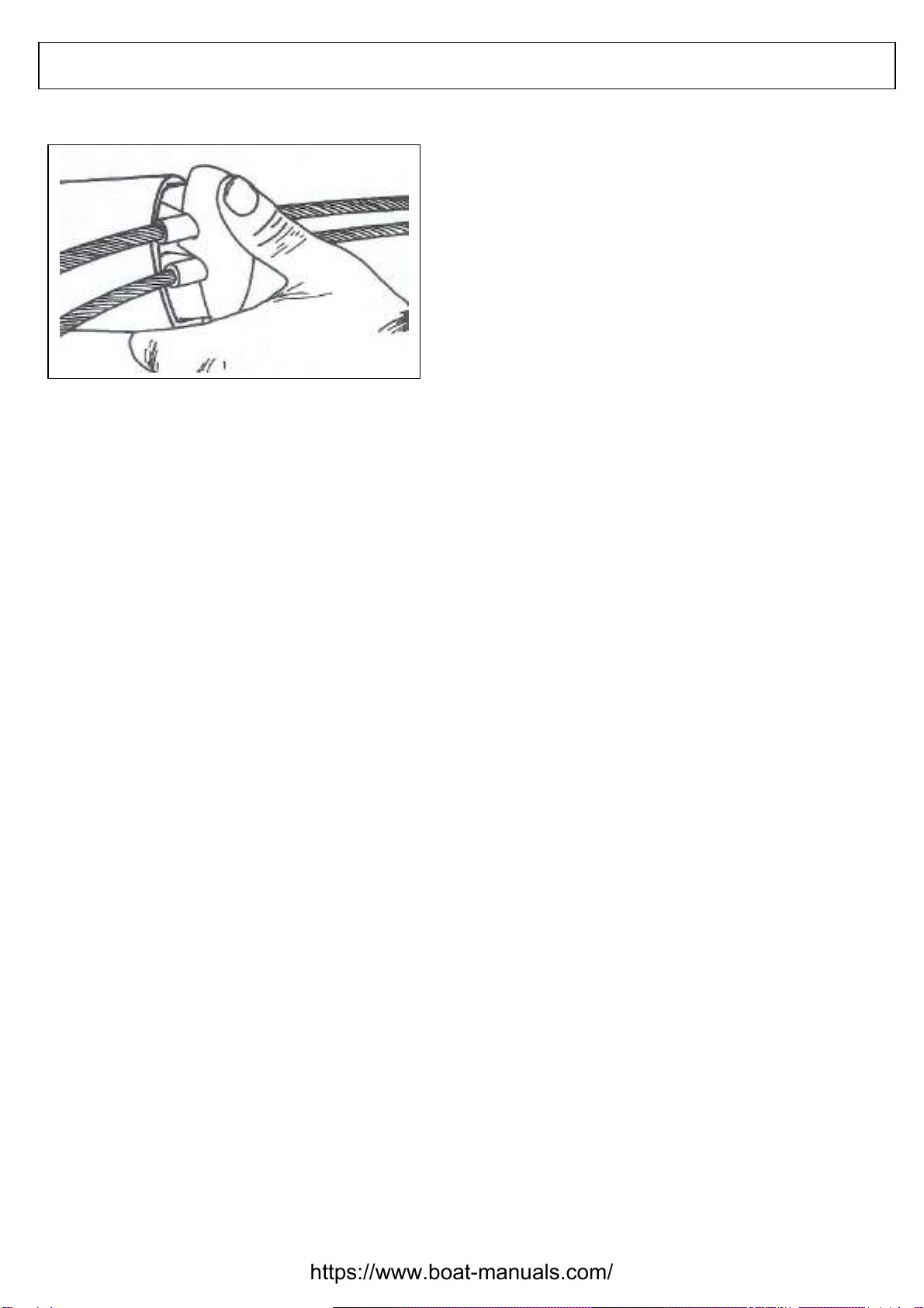
Fig. 4 Spreader end fitting, with stopper tubes.
Rigging the mast
Fit the spreader sections (long ones at the
bottom, short ones at the top). Self-locking nuts
are also provided.
The roller furling system, which forms part of
the cruising package, is supplied with the boat
as a complete kit with forestay. Assemble the
system and secure it to the mast mounting-
plate provided, as shown in the detailed
instructions.
Fix the upper and middle shrouds into the
spreader end-fittings, so that the stopper
ferrules pressed onto the shrouds lie below the
spreaders (see Fig. 4). The end-fittings are
fastened to the spreader sections by a screw.
Watch out for sharp edges (see Tip, Page 11).
Once the spreaders have been fitted, lay out
the lines clearly: Main Halyard & Topping Lift
aft of the mast, Jib, Spinnaker and/or masthead
Gennaker Halyards forward of the mast.
Signal Halyards (port & starboard) are attached
to the lower spreaders with a small block.
Belay the lines to cleats below on the mast.
The Main-Drop lines emerge from the mast
beneath the top pair of spreaders, and are first
led through small blocks under the spreaders,
then downwards. Lead the other lazy jack lines
through the eyes at the lower ends (see
diagram, Page 13) and secure them to the foot
of the mast for the time being.
Attaching Masthead fittings
Fit the Windex wind indicator, following the
manufacturer’s instructions on the packaging. A
threaded hole is provided in the masthead for
this purpose.
Fit the white all-round light (anchor light):
Remove the protective cap for both Tri-colour
and all-round lights (special accessory) and fit
the light onto the base.
To fit an electronic Wind Transducer:
The bracket is fitted to the masthead. Place the
arm of the wind transducer into it and tighten
the lock nut.
To fit a VHF aerial on the special brackets
already fitted on the masthead, follow the
manufacturer’s instructions.
If further cables are required for electronic
equipment, this can be drawn through with the
aid of the guide lanyard, which emerges at the
foot and head of the mast.
Dehler 35 cws
8
https://www.boat-manuals.com/

A strip of blue decorative tape is glued to the
sides of the mast, which can be used to
monitor mast trim. The tape is vulnerable to
chafing. Watch out for this when stepping the
mast, or when the boat is laid up for winter.
Fig. 5 Preparing the masthead for fitting the wind
transducer, aerial and tri-colour light
Fig. 6 Fitting the Wind Transducer
Fig. 7 Masthead with Windex fitted.
Stepping the mast
Prepare the Backstay tackle, as shown in the
diagram on Page 10.
Place a hoisting loop with two eyes around the
mast, equally spaced between the two pairs of
spreaders. Attach the two eyes to the crane hook.
The loop encircles all the lines, and should be
secured to prevent it riding up the mast, by a line
that is belayed to the foot of the mast.
TIP
Lengthen the guide lanyard by as much
again when using it. When inserting a
cable or line, the extended lanyard will
be drawn through the mast with it and is
then ready for feeding further
cables
/lines.
TIP
You will save time by having all the
rigging screws unscrewed to the same
length. Remove the lower split pins and
clevis pins from the rigging screw forks.
TIP
Use a hoisting loop long enough to drop
back down with the hook, once the mast
is stepped, so that it lies within easy
reach and can be released.
Dehler 35 cws
9
https://www.boat-manuals.com/

An experienced crewmember is now required
to take hold of the foot of the mast while it is
being raised upright by the crane, and guide it
to the leadthrough in the deck. The mast foot
and tabernacle are designed so that they seat
automatically below deck, and no further
adjustment is needed.
As soon as the mast has been stepped, it
should be secured to prevent it from falling
over. The roller furling system, shrouds and
stays can now be attached in the usual
sequence.
Fig. 8 1. Upper single blocks
2. Triple block
3. Triple block with becket
4. Lever clutch
5. Securing strop
Mast collar for deck leadthrough
Care is required when fitting the mast collar
each time the mast is stepped, as any mistake
will result in leaks around the mast. Fig. 9
illustrates the arrangement. The mast is sealed
off inside (8), and any water that penetrates the
mast drains off through the drain hole (2). A
sealing strip seals the mast between the
section and the collar.
Before the collar is fastened to the deck yoke,
a supporting rubber gasket can be inserted into
the gap and secured with a band clamp. If the
mast is not watertight, water will collect in the
inner cover (6) or run down into the boat
between the mast section and the inner mast
casing (7).
Fig 9 Mast leadthrough
1. Mast
2. Drain hole
3. Mast collar
4. Hose clip
5. Inner skin
6. Plastic cover
7. Mast casing
8. Seal inside mast
9. Sealing strip
10.Supporting rubber gasket
11. Deck
12. Deck reinforcement
13. Mast section
Dehler 35 cws
10
https://www.boat-manuals.com/

Tuning the mast
Fasten the shrouds to the eyes of the
chainplates, as shown in the diagram on
Page 7.
The forestay/roller furling system is of fixed
length and has no rigging screw. Tighten
the standing backstay tackle so that the
mast bends aft.
Tension the upper and middle shrouds
equally, so that the section flexes forward
by roughly 2 mast widths. Then draw the
mast back by one mast width using the
lower and auxiliary shrouds. To do this,
measure the distance between the threaded
rods in the rigging screws.
Now tension the remaining shrouds in pairs,
one after the other.
A glance up the mast track will reveal
whether the shrouds have been tensioned
equally: the mast track must be straight and
there should be no S-bend in the mast.
The standing backstay must always be
under tension when sailing. The limit strop
prevents the line from running out.
Fig. 10 Shrouds can be tensioned more easily with a
mole wrench & spanner.
TIP
A 21mm open-jaw spanner (or mole
grips) and a spanner of sufficient size
are suitable tools for tensioning the
shrouds.
TIP
A permanently attached and taut Main
halyard secured to the gooseneck can
be used to monitor the success of the
tuning operation
TIP
The clevis pins in the rigging screws
should run through the chainplate
eyes from outboard to inboard. Wrap
tape round the rigging screws to
prevent the sharp ends of the split
pins, used for securing, from causing
injury.
Dehler 35 cws
11
https://www.boat-manuals.com/

Fig 11. When the distance between the threaded
rods in the rigging screws is the same, then the
respective pair of shrouds is trimmed correctly.
The DEHLER Main-Drop-System
Battened Mainsail with integral canvas
sleeve and furling lines (lazy-jacks) for the
7/8th rig of the DEHLER 35 CWS.
Fully battened sails were first used
successfully on yachts many years ago,
and have now been revived thanks to the
development of new types of sailcloth.
The new cut of the battened Mainsail offers
the perfect combination of Mainsail
trimability and ultimate ease of handling.
The full-length battens maintain the efficient
shape of the Mainsail and prolong its life,
preventing the sail from flogging noisily
when it is being set, stowed or reefed, and
thereby reducing strain on the material.
The sail battens ideally complement the
main-drop system with integral canvas
boom cover and lazy-jacks. Fixed to each
side of the boom is a strip of tough, durable
Vinyl fabric, which protects the stowed
Mainsail.
Once the zip has been unfastened, the
mainsail can be set. The strips on both
sides are held up by the lazy-jacks. When
the sail is being stowed, it drops down onto
the boom into the cover, guided by the lazy-
jacks. A quick straightening of the sail, then
close the zip and the sail is stowed.
If the Mainsail is to be out of use for any
length of time, cover it at the mast with the
extra canvas cover.
When moored up, ensure that the boom
slopes downward sufficiently aft enough to
allow rainwater to drain easily.
TIP
When lowering or hoisting the Mainsail,
make sure that the boat is lying exactly
head to wind.
TIP
Spray the mainsail slides
occasionally with a lubricant. This
will make it considerably easier to
hoist the mainsail.
Dehler 35 cws
12
https://www.boat-manuals.com/

Fig. 12 Attaching the furling lines (lazy-jacks)
Attaching the boom
Fitting the main-drop sailcover
Fit the boom on the gooseneck with the aid
of a crewmember and secure it with the
bolt. The topping lift is fastened to the eye
on end of the boom by a knot and the boom
is hauled into a horizontal by tensioning the
topping lift at the mast.
The mainsheet is routed partly through the
boom, and for this reason is secured on the
boom. The diagram on Page 14 shows how
the mainsheet line is routed. The Halyard
routing diagram on Page 16 shows the
routing of the mainsheet to the starboard
coaming winch.
Fig. 13 shows how the kicking strap is
attached, and the diagram on Page 16
shows how it is routed back to the cockpit.
Fig. 13 Boom kicking strap
Insert the boom cover for the main-drop
system into the grooves on the boom, from
fore to aft. The wide end of the cover should
be at the mast end, with the zip on the
inside.
Insert the stiffening battens into the batten
pockets in the cover, from fore to aft.
Dehler 35 cws
13
https://www.boat-manuals.com/

Attach the lazy-jack lines (furling lines) to
the cover sections, as shown in Fig. 14.
Belay the lines on their mast cleats.
Make sure that the topping lift is always
under greater tension than the lazy-jack
lines, otherwise these could be torn out of
the boom cover.
Mainsheet routing
Bending on the Mainsail
Fig. 14 Before bending on the mainsail, haul up one
side of the main-drop cover.
Make sure that the deck has been washed
before unpacking the mainsail.
-Guide the foot of the mainsail into the
boom groove, from fore to aft.
-Fasten the tack of the sail to the forward
boom fitting.
-Shackle the clew outhaul to the clew.
-Lift the slide stopper clear of the mast
track, feed the mainsail slides into the
mast track then close the slide stopper.
-Insert the sail battens into their pockets,
from luff to leech (see description on
Page 15).
-Shackle Main halyard to headboard.
Make sure that the halyard shackle pin
is properly engaged.
-Shackle the guide blocks for Reef 1 &
Reef 2 pendant lines to their leech
webbing strops.
TIP
Ensure that the batten ends are
protected by tape or a thin plastic cap.
TIP
Before bending on the mainsail, haul up
one side of the main-drop cover a little
way by its lazy-jacks, and let the other
side hang down. This makes it easier to
control the sailcloth.
Dehler 35 cws
14
https://www.boat-manuals.com/

-Fasten the forward end of the reef
pendant lines to the luff webbing/rings
with bowlines or patent hook.
Patches
When a boat is running with the mainsail
eased off, the sailcloth comes into contact
with the spreaders and shrouds. This
increased mechanical load can lead to
chafe, damaging the material and seams.
A battened mainsail is particularly prone to
chafe; therefore 14 patches are supplied
with the mainsail. These should be affixed
at precisely the points where the sail and
shrouds or spreaders come into contact.
Wait until the mainsail shows the first signs
of light soiling at the points where the
patches should be stuck on.
The area to be protected from the vertical
sections of the upper shrouds can be
measured, and patches can affixed here
before the boat is taken out for the first
time. Patches are stuck to both sides of the
sail at all points.
Fig. 15 Patches protect the mainsail against chafe.
Inserting and tensioning the sail battens
The sail battens are supplied bent into a
circle, and so are under tension. Caution is
advised when unpacking them.
Ensure that the ends of the battens are
always protected by plastic caps that are
glued in place.
First lead the fabric tongue on the
tensioning sleeve back through the
tensioner.
Fig. 16a
TIP
It takes two people to bend on the heavy
sail. Make sure that the sail slides are
inserted into the mast track in the correct
order, and that they are not upside down.
TIP
Put a figure-of-eight knot in the forward
reef pendant lines before unbending the
sail, to prevent them from disappearing
into the boom.
Dehler 35 cws
15
https://www.boat-manuals.com/

Feed each batten according to length under
the metal bridge of the tensioning device,
and into its relevant batten pocket, working
from fore to aft. Some adjustment of the
batten length may be required.
Guide the webbing tongue around the
forward end of the batten and back aft
under the metal bridge.
Fig. 16b
Thread the tongue into the clamping wedge.
Fig. 16c
Press the clamping wedge forward under
the metal bridge on the tensioning sleeve,
at the same time pulling on the tongue, and
then secure it with the lock tab.
Fig. 16d
Routing control lines to the Central
Winches
All halyards and reefing lines, together with
Jib Sheet and Kicking Strap, are routed via
deck sheaves and partly-concealed
conduits, to the coachroof winches or the
two coaming winches. The diagram in Fig.
17 suggests one way of leading the
halyards and lines aft.
Fig. 17 1. Port Jib Sheet
2. Reef 2/ Pole downhaul
3. Reef 1.
4. Port Jib car adjustment
5. Spinnaker halyard
6. Pole uphaul
7. Masthead fore halyard
8. Cunningham
9. Kicking strap
10. Jib halyard
11. Starboard Jib car adjustment
12. Mainsheet
13. Main Halyard
14. Starboard Jib sheet
15. Roller Reef line
The number of lines led aft will vary
according to specification.
Dehler 35 cws
16
https://www.boat-manuals.com/

If the boat’s specification includes a
spinnaker and the pole downhaul is to be
led aft, we recommend replacing Reef 2,
which is then taken forward and belayed on
the mast.
If possible, tie control lines together into a
bundle, which is fed aft using a length of
stiff wire.
When unrigging, don’t forget to pull
messenger lines through the outer halyard
conduits.
Fig. 18
Control lines, and a stiff wire, are bound with tape side-
to-side in a flat bundle, and are pulled aft through the
conduit below deck.
Headsail
Topp Reff 2090 below-deck roller
headsail system
The Topp Reff roller furling system has
been tried and tested on many boats. When
it is combined with the cruising jib and the
Dehler quick reefing mechanism, a wide
range of wind strengths can be covered
without having to change sail. Please refer
to Page 20. The system can be fitted and
dismantled easily on the specially extended
forestay. See the instructions on fitting
included among the documents
accompanying your boat.
Fig. 19 Roller furling system
TIP
It is difficult to pull lines with frayed ends
through the narrow duct. Check the ends
at the close of each season.
Dehler 35 cws
17
https://www.boat-manuals.com/

The forestay acts as the load-bearing
element in the roller system, with the tube
section foil being used only to furl the sail
evenly and cleanly. The system is attached
to the mast using the T-terminal toggle
supplied. When stepping the rig, the
complete system is raised up with the mast
and the foot of roller system is taken
forward. The drum is guided into the anchor
locker at the same time as the mast foot is
lowered through the deck aperture.
The control line runs under the deck and is
belayed on a clutch aft in the cockpit
coaming.
-Functioning of the system is guaranteed
only if the halyard swivel/slide is at the
end of the section tube when the sail is
bent on.
-Bear in mind that the control line, due to
the right-hand twist of the forestay wire,
must be reeled in counter-clockwise, so
that when the sail is being furled the
system rotates in a clockwise direction.
-Haul in the spinnaker halyard tight when
not in use, to prevent it being rolled up in
the Furler.
-When the boat is not in use for long
periods, furl the sail tightly and secure it
with a strop at the clew, or unbend it.
-A canvas headsail cover (with a
tensioning line at the back) will protect
the sail against ultra-violet radiation and
keep it clean.
DEHLER 35 CWS winch system
This system can only be fully exploited if the
cockpit coaming winch has an electric winch
motor. The electric switches for first and
second speeds are located in four easily-
accessible positions. Pressing a switch sets the
relevant coaming winch in motion.
Stow lines that are not in use in the line bags.
Mark all clutch levers to indicate which are for
sheets and which are for halyards. Instructions
on servicing the electric winches are included
in the information supplied by Harken.
ATTENTION !
The electric winch drive is very powerful,
and the winch should be used with care.
Halyards and reefing lines under extreme
load must be hauled in on the winch before
the clutch lever is released, otherwise the
lever mechanism will be damaged. If the
clutch lever is pointing aft horizontally, the
line is free to run.
TIP
The clutch lever for the leeward jib
sheet should always be pointing aft
horizontally,
Dehler 35 cws
18
https://www.boat-manuals.com/

DEHLER quick-reefing system
The DEHLER quick-reefing system, in
conjunction with the Main-drop system
facilitates swift and easy reefing of the
mainsail from the cockpit by a single crew
member. This applies to both the first and
second reefs.
Both luff and leech are hauled down onto
the boom at the same time, using the
reefing line.
Attach the two reefing lines as shown in the
diagram in Fig. 20.
Once the mainsail halyard has been
slackened off, haul Reef 1 or Reef 2 line in
tightly, using the electric winch.
ATTENTION !
If the forward reef cringle does not fall onto
the boom parallel to the aft cringle, you
must pull the rear reefing line. Failure to do
this will result in the cloth around the reef
cringle being torn.
The sail drops onto the boom between the
Main-drop cover sections. It is not covered.
The clutch is then closed on the reefing line.
Fig. 20 Guide block at the leech reef cringle.
The luff of the reefed mainsail is then re-
tensioned with the halyard.
The mainsheet, kicking strap and standing
backstay are then re-trimmed.
TIP
Before commencing reefing, slacken off
the mainsheet, Cunningham and
kicking strap.
TIP
Mark the clutch levers by the central
winch, to show which control the main
halyard and reefing lines.
Dehler 35 cws
19
https://www.boat-manuals.com/

Masthead Genaker
In light winds, a masthead Genaker of
approximately 70 square meters can be
carried instead of the normal jib or cruising
jib. With the Genaker, the DEHLER 35CWS
quickly reaches its best speed on any
course.
The masthead Genaker is set flying
between the spinnaker pole, which is
extended as a bowsprit, and the masthead.
Pull the tack of the sail to the eye of the
spinnaker pole, using a tack line that is then
belayed on a bow deck cleat. Haul the luff
tight using the masthead Genaker halyard.
The Genaker is controlled by sheets led
through blocks attached 9with stand-up
springs) to toe rail plates, and the coaming
winch which can be operated either
manually or electrically.
Roller-furled high aspect jib
The biradial-cut sail is manufactured from
differing cloth strengths. A continuous
fibreglass sail batten running parallel to the
forestay ensures that the sail is furled
cleanly.
The leech is cut concave and has no further
battens. The sail is also equipped with
trimming lines in the foot and leech.
The headsail sliding cars are infinitely
adjustable on their own tracks, and
adjustments are made by control lines led
to clutches on the coachroof to port and
starboard.
Fig. 22 DEHLER 35 CWS with masthead
spinnaker and normal spinnaker.
TIP
Hoist the sail in its sleeve (snuffer) with
the jib still up. Then ease the snuffer
sleeve up to the masthead and belay
the endless line to a mast cleat. Only
then should the jib be furled.
TIP
To achieve optimum sail shape after
the first reef stage, the sail batten must
be rolled up fully. When the sail is re-
trimmed, the upper and lower batten
ends should no longer be visible
Dehler 35 cws
20
https://www.boat-manuals.com/
Table of contents
Other Dehler Boat manuals
Popular Boat manuals by other brands

Bayliner
Bayliner 255 Cruiser owner's manual

Horizon Yacht Charters
Horizon Yacht Charters Astrea 42 2019 Information & operation manual

Creek Company
Creek Company ODC XR 12 Assembly instructions

ROBfin
ROBfin Hobit user manual

Yamaha
Yamaha 212SS owner's manual

Hansa Sailing
Hansa Sailing 303 Wide owner's manual