Deif PPU User manual

DEI
F
A/
S
PPU Power Management (PPM)
4189340409I (UK)
Installation Instructions
Diesel generator I/O
s
Shaft generator/Shore connection I/Os
Bus tie generator I/Os
Wiring
DEIF A/S, Frisenborgvej 33 Tel.: +45 9614 9614, Fax: +45 9614 9615

PPM Installation Instructions
DEIF A/S Page 2 of 69
Table of contents
1. ABOUT THIS DOCUMENT....................................................................................................3
INTENDED USERS..........................................................................................................................3
CONTENTS/OVERALL STRUCTURE..................................................................................................3
DEFINITIONS ................................................................................................................................3
2. WARNINGS AND LEGAL INFORMATION ...........................................................................4
LEGAL INFORMATION AND RESPONSIBILITY..................................................................................... 4
ELECTROSTATIC DISCHARGE AWARENESS .....................................................................................4
SAFETY ISSUES ............................................................................................................................4
3. GENERAL HARDWARE DESCRIPTION ..............................................................................5
HARDWARE..................................................................................................................................5
4. DIESEL GENERATOR I/OS...................................................................................................6
DG UNIT WITH PMS PROCESSOR ..................................................................................................6
DG UNIT WITHOUT PMS PROCESSOR..........................................................................................20
5. SHAFT GENERATOR I/OS..................................................................................................34
SG WITH FIXED FREQUENCY .......................................................................................................34
6. BUS TIE BREAKER I/OS.....................................................................................................45
BUS TIE BETWEEN DG AND SG ...................................................................................................45
7. ADDITIONAL OPERATOR PANEL .....................................................................................54
INSTALLATION OF AOP-2 ............................................................................................................54
8. WIRINGS ..............................................................................................................................57
AC CONNECTIONS (3-PHASE)......................................................................................................57
INTERNAL CANBUS WIRING.........................................................................................................58
OPTION H2, MODBUS RTU.........................................................................................................58
LOAD SHARING LINES..................................................................................................................60
MECHANICAL SPEED GOVERNOR (STANDARD) .............................................................................. 61
AVR WITH RELAY OUTPUTS.........................................................................................................61
ELECTRONIC SPEED GOVERNOR..................................................................................................62
AVR WITH ANALOGUE OUTPUTS (REQUIRES OPTION D) ................................................................62
BINARY INPUTS........................................................................................................................... 63
BINARY INPUTS WITH WIRE BREAK SUPERVISION ..........................................................................63
ANALOGUE INPUTS .....................................................................................................................64
OPTOCOUPLER OUTPUTS FOR EXTERNAL COUNTER......................................................................64
9. GENERAL DATA .................................................................................................................65
TECHNICAL SPECIFICATIONS .......................................................................................................65
UNIT DIMENSIONS .......................................................................................................................68
PANEL CUTOUT (IN MM)...............................................................................................................69

PPM Installation Instructions
DEIF A/S Page 3 of 69
1. About this document
This document is the Installation Instructions for DEIF’s PPU Power Management system PPM.
The document mainly includes general hardware description, I/O lists for diesel, shaft and bus tie
generator, wiring descriptions and FAT information.
The general purpose of these installation instructions is to give the user important information to be
used in the installation of the PPM system.
Intended users
These installation instructions are mainly intended for the panel builder designer in charge. On
the basis of this document, the panel builder designer will give the electrician the information he
needs in order to install the PPM system, e.g. detailed electrical drawings. In some cases the
electrician may use these installation instructions himself.
Contents/overall structure
This document is divided into chapters, and in order to make the structure simple and easy to
use, each chapter will begin from the top of a new page.
Definitions
Throughout this document a number of notes and warnings will be presented. To ensure that these
are noticed, they will be highlighted in order to separate them from the general text.
Notes
Warnings
Please make sure that you read this manual before starting to work with the
PPM system. Failure to do this could result in damaging the equipment or
even worse injury of personnel.
The notes provide general information which will be helpful for the reader to
bear in mind.
The warnings indicate a potentially dangerous situation which could result in
death, personal injury or damaged equipment, if certain guidelines are not
followed.

PPM Installation Instructions
DEIF A/S Page 4 of 69
2. Warnings and legal information
Legal information and responsibility
DEIF takes no responsibility for installation or operation of the generator sets. If there is any
doubt about how to install or operate the generator sets controlled by the PPM system, the
company responsible for the installation or the operation of the sets must be contacted.
Electrostatic discharge awareness
Sufficient care must be taken to protect the terminals against static discharges during the
installation. Once the system is installed and connected, these precautions are no longer
necessary.
Safety issues
Installing the system implies work with dangerous currents and voltages. Therefore, the
installation should only be carried out by authorised personnel who understand the risks involved
in working with live electrical equipment.
Be aware of the hazardous live currents and voltages. Do not touch any AC
measurement inputs as this could lead to injury or death.
The system units are not to be opened by unauthorised personnel. If opened anyway,
the warranty will be lost.

PPM Installation Instructions
DEIF A/S Page 5 of 69
3. General hardware description
Hardware
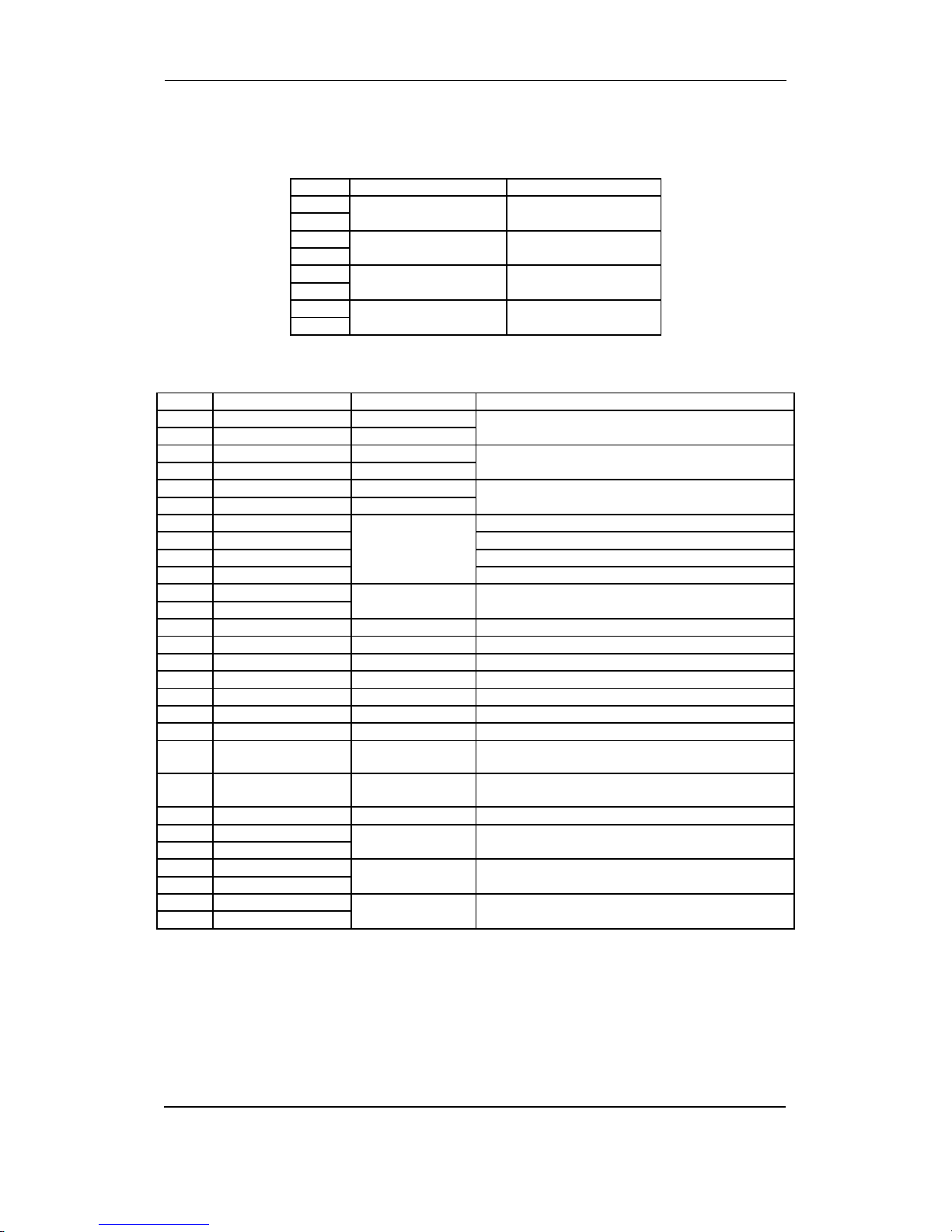
The unit housing is divided into board slot positions. This means that the unit consists of a
number of printed circuit boards (PCBs) mounted in numbered slots. The green terminal blocks
are then mounted in the PCBs. Some of these board slots are standard, and some are intended
for options. The board slot positions are arranged as illustrated below.
Term. DG SG/SC TB Description
Slot #1 1-28 Standard Standard Standard Power supply board
Slot #2 29-36 H2 H2 H2 Option: External comm.
Slot #3 37-64 Standard Standard Standard Load sharing and
input/output board
Slot #4 65-72 Standard Not used Not used Outputs for governor/AVR
according to choice of types
Slot #5 73-89 Standard Standard Standard AC measuring
Slot #6 90-125 F1,
M15, M16,
M18
F1,
M15, M16,
M18
F1,
M15, M16,
M18
Option: F1 analogue
transducer outputs,
M15 (4 x 0(4)…20 mA inputs),
M16 (7 x binary inputs),
M18 (4 x relay outputs)
Slot #7 98-125 Standard Standard Not used Engine interface board
Slot #8 126-133 Standard Standard Standard Internal CANbus
Unit top side overview
An overview of the terminals is presented below. The slot positions are as follows:
Ethernet
787776757473 96 979594929190 93
89888785 8683 8482818079
727169 70686765 66
62 6359 60 615856 575553 54 645251504947464443 45 4841403837 39 42
USB Memory Service port Display
Ethernet
PMS CAN
Engine CAN
USB
Power
Self check ok
Alarm inhibit
SLOT # 1
SLOT # 3
SLOT # 5
SLOT # 7
SLOT # 2
SLOT # 4
SLOT # 6
SLOT # 8

PPM Installation Instructions
DEIF A/S Page 6 of 69
4. Diesel generator I/Os
DG unit with PMS processor
Terminal strip overviews
Slots #1, #2, #5 and #6
36 SLOT # 2
external
comm.
OPTION
H2
363636
35353535
34343434
33333333
32323232
31313131
30303030
29292929
28282828
27272727
26262626
25252525
24242424
23232323
22222222
21212121
20202020
19191919
18181818
17171717
16161616
15151515
14141414
13131313
12121212
11111111
10101010
9999
8888
7777
6666
5555
4444
3333
2222
1111
36363636
35353535
34343434
33333333
32323232
31313131
30303030
29292929
28282828
27272727
26262626
25252525
24
242424
23232323
22222222
21212121
20202020
19191919
18181818
17171717
16161616
15151515
14141414
13131313
12121212
11111111
10101010
9999
8888
7777
6666
5555
4444
3333
2222
1111
36363636
35353535
34343434
33333333
32323232
31313131
30303030
29292929
28282828
27272727
26262626
25252525
24242424
23232323
22222222
21212121
20202020
19191919
18181818
17171717
16161616
15151515
14141414
13131313
12121212
11111111
10
101010
9999
8888
7777
6666
5555
4444
3333
2222
1111
36363636
35353535
34343434
33333333
32323232
31313131
30303030
29292929
28282828
27272727
26262626
25252525
24242424
23232323
22222222
21212121
20202020
19191919
18181818
17171717
16161616
15151515
14141414
13131313
12121212
11111111
10101010
9999
8888
7777
6666
5555
4444
3333
2222
1111
COMMON (TERM. 23-27)
PMS CONTROL
Configurable/Secured ON
Configurable/Secured OFF
Shore pos. OFF
Forced SWBD
COMMON (TERM. 20-21)
Configurable (Relay 26)
Configurable (Relay 27)
binary
optocoupler
SLOT # 1
inputs
CB ON
Sync.
transistor
output
relay
output
CB OFF
Open breaker RELAY 4
PMS
Alarm RELAY 3
Configurable/Trip NEL2 RELAY 2
Configurable/Trip NEL1 RELAY 1
STATUS relay
97979797
96969696
95959595
94949494
93939393
92929292
91919191
90909090
89898989
88888888
87878787
86868686
85858585
84848484
83838383
82828282
81818181
80808080
79797979
78787878
77777777
76767676
75757575
74747474
73737373
97979797
96969696
95959595
94949494
93939393
92929292
91919191
90909090
89898989
88888888
87878787
86868686
85858585
84848484
83838383
82828282
8181
8181
80808080
79797979
78787878
77777777
76767676
75757575
74747474
73737373
97979797
96969696
95959595
94949494
93939393
92929292
91919191
90909090
89898989
88888888
87878787
86868686
85858585
84848484
83838383
82828282
81818181
80808080
79797979
78787878
77777777
76767676
75757575
74747474
73737373
97979797
96969696
95959595
94949494
93939393
92929292
91919191
90909090
89898989
88888888
87878787
86868686
85858585
84848484
83838383
82828282
8181
8181
80808080
79797979
78787878
77777777
76767676
75757575
74747474
73737373
SLOT # 6
SLOT # 5
OPTION
F1
M15, M16, M18
L2L2L2L2L2L2L2L2L2L2L2L2
L3
Neutral
L2L2
L1
Neutral
L3
L2
L1
S2 (l)
S1 (k) L3 AC CURRENT
S2 (l)
S1 (k) L2 AC CURRENT
S2 (l)
S1 (k) L1 AC CURRENT
GENERATOR
VOLTAGE
BUSBAR
VOLTAGE
various
inputs/
outputs
Supply
DC Power
The functionality of the boards in slot #2 and slot #6 is optional.

PPM Installation Instructions
DEIF A/S Page 7 of 69
Slots #3, #4, #7 and #8
The functionality of the boards in slot #4 is optional.
72 SLOT # 4
727272
71717171
70707070
69696969
68686868
67676767
66666666
65656565
64646464
63636363
62626262
61616161
60606060
59595959
58585858
57575757
56565656
55555555
54545454
53535353
52525252
51515151
50505050
49494949
48484848
47474747
46464646
45454545
44444444
43434343
42424242
41414141
40404040
39393939
38383838
37373737
72727272
71717171
70707070
69696969
68686868
67676767
66666666
65656565
64646464
63636363
62626262
61616161
60606060
59595959
58
585858
57575757
56565656
55555555
54545454
53535353
52525252
51515151
50505050
49494949
48484848
47474747
46464646
45454545
44444444
43434343
42424242
41414141
40404040
39393939
38383838
37373737
72727272
71717171
70707070
69696969
68686868
67676767
66666666
65656565
64646464
63636363
62626262
61616161
60606060
59595959
58585858
57575757
56565656
55555555
54545454
53535353
52525252
51515151
50505050
49494949
48484848
47474747
46464646
45454545
44
444444
43434343
42424242
41414141
40404040
39393939
38383838
37373737
7272
71717171
70707070
69696969
68686868
67676767
66666666
65656565
64646464
63636363
62626262
61616161
60606060
59595959
58585858
57575757
56565656
55555555
54545454
53535353
52525252
51515151
50505050
49494949
48484848
47474747
46464646
45454545
44444444
43434343
42424242
41414141
40404040
39393939
38383838
37373737
Configurable
COMMON (TERM. 43-55)
SLOT # 3
RELAY 9
RELAY 8
RELAY 7
RELAY 6
133133133133
132132132132
131131131131
130130130130
129129129129
128128128128
127127127127
126126126126
114114114114
113113113113
112112112112
111111111111
110110110110
109109109109
108108108108
107107107107
106106106106
105105105105
104104104104
103103103103
102102102102
101101101101
100100100100
99999999
133
133133133
132132132132
131131131131
130130130130
129129129129
128128128128
127127127127
126126126126
114114114114
113113113113
112112112112
111111111111
110110110110
109109109109
108108108108
107107107107
106106106106
105105105105
104104104104
103103103103
102102102102
101101101101
100100100100
99999999
133133133133
132132132132
131131131131
130130130130
129129129129
128128128128
127127127127
126126126126
114114114114
113113113113
112112112112
111111111111
110110110110
109109109109
108108108108
107107107107
106106106106
105105105105
104104104104
103103103103
102102102102
101101101101
100100100100
99999999
SLOT # 8
SLOT # 7
GND
4-20 mA Configurable
GND
HC2 variable load/Configurable
GND
internal
comm.
125125125125
124124124124
123123123123
122122122122
121121121121
120120120120
119119119119
118118118118
117117117117
116116116116
115115115115
125125125125
124124124124
123123123123
122122122122
121121121121
120120120120
119119119119
118118118118
117117117117
116116116116
115115115115
125125125125
124124124124
123123123123
122122122122
121121121121
120120120120
119119119119
118118118118
117117117117
116116116116
115115115115
125125125125
124124124124
123123123123
122122122122
121121121121
120120120120
119119119119
118118118118
117117117117
116116116116
115115115115
98
relay
outputs
Lower
Raise
SPEED
Configurable
Start ACKN. HC 2/Configurable
Start ACKN. HC 1/Configurable
CB CLOSED
CB OPEN
Load dependent stop block
Configurable
ALARM INHIBIT 2/Configurable
ALARM INHIBIT 1/Configurable binary
optocoupler
inputs
NOT USED!
REACTIVE (Q) LOAD SHARING
COMMON SET POINTS
ACTIVE (P) LOAD SHARING
-10..0..10 VDC
-5....0....5 VDC
CAN-HCAN-HCAN-HCAN-H
CAN-LCAN-LCAN-LCAN-L
CAN-HCAN-HCAN-HCAN-H
CAN-LCAN-LCAN-LCAN-L
EMERGENCY STOPEMERGENCY STOPEMERGENCY STOPEMERGENCY STOP
ConfigurableConfigurableConfigurableConfigurable
COMMONCOMMONCOMMONCOMMON
CAN-HCAN-HCAN-HCAN-H
CAN-LCAN-LCAN-LCAN-L
CAN-HCAN-HCAN-HCAN-H
CAN-LCAN-LCAN-LCAN-L
EMERGENCY STOPEMERGENCY STOPEMERGENCY STOPEMERGENCY STOP
ConfigurableConfigurableConfigurableConfigurable
COMMONCOMMONCOMMONCOMMON
CAN-HCAN-HCAN-HCAN-H
CAN-LCAN-LCAN-LCAN-L
CAN-HCAN-HCAN-HCAN-H
CAN-LCAN-LCAN-LCAN-L
EMERGENCY STOPEMERGENCY STOPEMERGENCY STOPEMERGENCY STOP
ConfigurableConfigurableConfigurableConfigurable
COMMONCOMMONCOMMONCOMMON
CAN-HCAN-HCAN-H
CAN-LCAN-LCAN-LCAN-L
CAN-HCAN-HCAN-HCAN-H
CAN-LCAN-LCAN-LCAN-L
EMERGENCY STOPEMERGENCY STOPEMERGENCY STOPEMERGENCY STOP
ConfigurableConfigurableConfigurableConfigurable/Shaft (or Shore) mode
RPM PICKUP
COMMONCOMMONCOMMONCOMMON (TERM. 104-106)
REMOTE STARTREMOTE STARTREMOTE STARTREMOTE START
RUNNING FEEDBACKRUNNING FEEDBACKRUNNING FEEDBACKRUNNING FEEDBACK
READY FOR OPERATIONREADY FOR OPERATIONREADY FOR OPERATIONREADY FOR OPERATION
REMOTE STARTREMOTE STARTREMOTE STARTREMOTE START
RUNNING FEEDBACKRUNNING FEEDBACKRUNNING FEEDBACKRUNNING FEEDBACK
READY FOR OPERATIONREADY FOR OPERATIONREADY FOR OPERATIONREADY FOR OPERATION
REMOTE STARTREMOTE STARTREMOTE STARTREMOTE START
RUNNING FEEDBACKRUNNING FEEDBACKRUNNING FEEDBACKRUNNING FEEDBACK
READY FOR OPERATIONREADY FOR OPERATIONREADY FOR OPERATIONREADY FOR OPERATION
COMMON (TERM. 114-118)
REMOTE STOP
REMOTE STARTREMOTE STARTREMOTE STARTREMOTE START
RUNNING FEEDBACKRUNNING FEEDBACKRUNNING FEEDBACKRUNNING FEEDBACK
READY FOR OPERATIONREADY FOR OPERATIONREADY FOR OPERATIONREADY FOR OPERATION
RELAY 20
RELAY 19
RELAY 18
START PREPARE
STOP
START
Configurable/Split mode
Configurable/Auto mode
Configurable/Semi-auto mode
Configurable
Configurable
Configurable
binary
optocoupler
inputs
0,5.....70 VAC
10...10000 Hz
with
wire break
supervision
analogue
transducer
inputs
HC1 variable load/Configurable
Configurable (Relay 13)/Lower U (option D)
Configurable (Relay 12)/Raise U (option D)
HC 2 FIXED LOAD/Configurable
HC 1 FIXED LOAD/Configurable
HC 2 CONNECTED/Configurable
HC 1 CONNECTED/Configurable
HC 2 REQUEST/Configurable
HC 1 REQUEST/Configurable
BLACKOUT
AVR Not used
Not used
Not used
Not used

PPM Installation Instructions
DEIF A/S Page 8 of 69
Terminal strip description
Slot #1, power supply and binary I/O
For the relay outputs the following terms will be used:
NO means Normally Open
NC means Normally Closed
Com. means common terminal for the relay in question
Term. Function Technical data Description
1 +12/24V DC 12/24V DC
-25/+30%
Power supply
2 0V DC
3 NC Status relay Normally closed relay, processor/power supply status
supervision
4 Com. 24 V/1A
5 NO Relay 1 Configurable/Trip NEL 1
6 Com. 250V AC/8A
7 NC
8 NO Relay 2 Configurable/Trip NEL 2
9 Com. 250V AC/8A
10 NC
11 NO Relay 3 PMS alarm
12 Com. 250V AC/8A
13 NC
14 NO Relay 4 CB OFF
Open breaker (deload)/trip
15 Com. 250V AC/8A
16 NC
17 NO Relay 5 CB ON
Close breaker (synchronising)
18 Com. 250V AC/8A
19 NC
20 Open collector 1 Transistor out configurable as standard relay output (relay number
26)
21 Open collector 2 Transistor out configurable as standard relay output (relay number
27)
22 Com. Common Common terminal for terminals 20 and 21
23 Binary input Optocoupler Configurable/Secured mode ON
24 Binary input Optocoupler Configurable/Secured mode OFF
25 Binary input Optocoupler Shore connection breaker position OFF
26 Binary input Optocoupler Forced switchboard control
27 Binary input Optocoupler PMS control
28 Com. Common Common for terminals 23-27
The power supply must be protected with a 1A fuse.

PPM Installation Instructions
DEIF A/S Page 9 of 69
Slot #2, external communication (option)
Option H2 (RS485 Modbus RTU).
Term. Function Description
29 DATA + (A) Modbus RTU, RS485
30 Not used
31 DATA - (B)
32 Not used
33 DATA + (A)
34 Not used
35 DATA - (B)
36 Not used
The serial communication line should be terminated between DATA + and DATA - with a resistor
equal to the cable impedance.
Slot #3, binary I/O
Term. Function Technical data Description
37 -5…0…5V DC Analogue I/O Active load sharing line
38 Com. Common Common for load sharing lines
39 -5…0…5V DC Analogue I/O Reactive load sharing
40 -10…0…10V DC Analogue input
NOT USED
41 Com. Common
42 -10…0…10V DC Analogue input
43 Binary input Optocoupler Blackout input from external relay (all breakers in
position OFF)
44 Binary input Optocoupler Heavy consumer 1 request/configurable
45 Binary input Optocoupler Heavy consumer 2 request/configurable
46 Binary input Optocoupler Heavy consumer 1 connected/configurable
47 Binary input Optocoupler Heavy consumer 2 connected/configurable
48 Binary input Optocoupler Heavy consumer 1 fixed load/configurable
49 Binary input Optocoupler Heavy consumer 2 fixed load/configurable
50 Binary input Optocoupler Alarm Inhibit 1/configurable
51 Binary input Optocoupler Alarm Inhibit 2/configurable
52 Binary input Optocoupler Configurable. User programmable
53 Binary input Optocoupler Load dependent stop blocking
54 Binary input Optocoupler CB open
55 Binary input Optocoupler CB closed
56 Com. Common Common for terminals 43-55
57 NO Relay 6 Start acknowledge Heavy consumer 1/configurable
58 Com. 250V AC 8A
59 NO Relay 7 Start acknowledge Heavy consumer 2/configurable
60 Com. 250V AC 8A
61 NO Relay 8 Configurable. User programmable
62 Com. 250V AC 8A
63 NO Relay 9 Configurable. User programmable
64 Com. 250V AC 8A

PPM Installation Instructions
DEIF A/S Page 10 of 69
Slot #4, GOV/AVR (standard)
GOV/AVR relay output card (GOV standard) (voltage control option D).
Term. Function Technical data Description
65 NO Relay 10
250V AC, 8A
Generator GOV
Increase frequency
66 Com.
67 NO Relay 11
250V AC, 8A
Generator GOV
Decrease frequency
68 Com.
69 NO Relay 12
250V AC, 8A
Generator AVR (option D)
Increase voltage/configurable
70 Com.
71 NO Relay 13
250V AC, 8A
Generator AVR (option D)
Decrease voltage/configurable
72 Com.
Option E1
GOV/AVR analogue output card.
Term. Function Description
65 Not used
66 +/-20 mA out Speed governor setpoint output
67 0
68 Not used
69 Not used
70 +/-20 mA out AVR voltage setpoint output
71 0
72 Not used
If necessary the current outputs can be converted to voltage using a resistor across the
terminals (250 will convert the +/-20 mA into +/-5V DC).
Voltage control setpoint to AVR is an option. If a combination of analogue
signals and relay signals is needed, then option EF4 is to be used.

PPM Installation Instructions
DEIF A/S Page 11 of 69
Option EF2
Analogue speed governor output and one transducer output.
Term. Function Description
65 Not used
66 +/-20 mA Speed governor setpoint output
67 0
68 Not used
69 Not used
70 0(4) - 20 mA out Analogue output 3
71 0
72 Not used
These outputs are active outputs, meaning that they have an internal power supply. The outputs
are galvanically separated from each other and from the rest of the unit. Via the display or the
PC programming software individual outputs can be selected to represent any AC measuring
value and related values e.g. power, power factor, frequency etc. Outputs can be selected to be
either 0…20 mA or 4…20 mA in the PC utility software. If necessary, the current outputs can be
converted to voltage using a resistor across the terminals (500 will convert the 0-20 mA into 0-
10V DC).

PPM Installation Instructions
DEIF A/S Page 12 of 69
Option EF4
Combination output for governor and AVR (option EF4).
Term. Function Description
65 ANA + Analogue +/-20 mA for GOV or AVR
66 ANA -
67 Not used
68 Not used
69 GOV relay up Relay output for GOV or AVR
Raise speed or voltage
70 GOV relay up
71 GOV relay down Relay output for GOV or AVR
Lower speed or voltage
72 GOV relay down
In the menu system it is possible to set the speed governor to either binary or analogue output.
With option D this selection regarding AVR control is also possible.
On the PCB there is only one set of relay outputs and one analogue output. This means that if
the relay outputs are used for speed control, then the analogue output will be used for the AVR,
and vice versa.
Slot #5, AC measuring
Term. Function Technical data Description
73 I L1 s1 Generator current L1 1/5 A AC input
74 I L1 s2
75 I L2 s1 Generator current L2 1/5 A AC input
76 I L2 s2
77 I L3 s1 Generator current L3 1/5 A AC input
78 I L3 s2
79 U L1 Generator voltage L1 Max. 690V AC phase - phase value
80 Not used
81 U L2 Generator voltage L2 Max. 690V AC phase - phase value
82 Not used
83 U L3 Generator voltage L3 Max. 690V AC phase - phase value
84 U neutral Generator voltage
neutral
For land-based applications only
85 U L1 Bus voltage L1 Max. 690V AC phase - phase value
86 Not used
87 U L2 Bus voltage L2 Max. 690V AC phase - phase value
88 U neutral Bus voltage neutral For land-based applications only
89 U L3 Bus voltage L3 Max. 690V AC phase - phase value
Current inputs are galvanically separated. Max. 0.3 VA per phase. Voltage
measurements are available (phase to phase) from 100V AC to 690V AC.

PPM Installation Instructions
DEIF A/S Page 13 of 69
Slot #6, inputs/outputs (I/Os)
Option F1
Analogue transducer output.
Term. Function Description
90 Not used
91 0 Analogue output 1, selectable
92 0(4) - 20 mA out
93 Not used
94 Not used
95 0 Analogue output 2, selectable
96 0(4) - 20 mA out
97 Not used
These outputs are active outputs, meaning that they have an internal power supply. The outputs
are galvanically separated from each other and from the rest of the unit. Via the display or the
PC programming software individual outputs can be selected to represent any AC measuring
value and related values e.g. power, power factor, frequency etc. Outputs can be selected to be
either 0…20 mA or 4…20 mA in the PC utility software. If necessary, the current outputs can be
converted to voltage using a resistor across the terminals (500 will convert the 0-20 mA into 0-
10V DC).
Option M15
4 x analogue 4-20 mA inputs.
Term. Function Description
90 Input 90 common Common
91 Analogue input 91+ 4-20 mA in
92 Input 92 common Common
93 Analogue input 93+ 4-20 mA in
94 Input 94 common Common
95 Analogue input 95+ 4-20 mA in
96 Input 96 common Common
97 Analogue input 97+ 4-20 mA in
Option M16
7 x binary inputs.
Term. Function Description
90 Common Common
91 Digital input Configurable
92 Digital input Configurable
93 Digital input Configurable
94 Digital input Configurable
95 Digital input Configurable
96 Digital input Configurable
97 Digital input Configurable
PPM Installation Instructions
DEIF A/S Page 14 of 69
Option M18
4 x relay outputs.
Term. Function Description
90 Relay output 14
250V AC, 8A max.
Configurable
91
92 Relay output 15
250V AC, 8A max.
Configurable
93
94 Relay output 16
250V AC, 8A max.
Configurable
95
96 Relay output 17
250V AC, 8A max.
Configurable
97
Slot #7, engine interface board
Term. Function Technical data Description/preconfiguration
98 Analogue input 1 + +4…20 mA in Heavy consumer 1 variable load/configurable
99 Analogue input 1 - GND
100 Analogue input 2 + +4…20 mA in Heavy consumer 2 variable load/configurable
101 Analogue input 2 - GND
102 Analogue input 3 + +4…20 mA in Configurable. User-programmable
103 Analogue input 3 - GND
104 Binary input With wire break
supervision
Wire break
resistor: 100
Configurable. User-programmable
105 Binary input Configurable. User-programmable
106 Binary input Configurable. User-programmable
107 Common Common terminals for 104-106
108 Tacho input 0.5…70V AC
10…10.000 Hz
RPM/magnetic pick-up/overspeed
109 Tacho input
110 Binary input Optocoupler Configurable/Semi-auto mode
111 Binary input Optocoupler Configurable/Auto mode
112 Binary input Optocoupler Configurable/Split mode
113 Binary input Optocoupler Configurable/Shaft (or Shore) mode
114 Binary input Optocoupler External emergency stop activated
115 Binary input Optocoupler Ready for operation (ON = ready, OFF = blocked)
116 Binary input Optocoupler Running feedback
117 Binary input Optocoupler Remote start (only active in SEMI-AUTO plant
mode)
118 Binary input Optocoupler Remote stop (only active in SEMI-AUTO plant
mode)
119 Com. Common Common for terminals 114-118
120 NO Relay 18
250V AC/8A
Start
121 Com.
122 NO Relay 19
250V AC/8A
Stop coil/running coil (selectable)
123 Com.
124 NO Relay 20
250V AC/8A
Start prepare
125 Com.

PPM Installation Instructions
DEIF A/S Page 15 of 69
The engine interface board consists of configurable inputs and outputs. The configuration is
performed via the PC utility software, and the default settings can be changed to the relevant
settings. For input configuration, upload the parameter list from the unit and select the input in
question. Then a configuration dialog box will appear, and the settings can be changed. The
standard title (e.g. 4-20 mA in no. 1) can be changed, and the new title will also be shown in the
display. The minimum and maximum values of the 4-20 mA input can be adjusted:
Value: Nominal heavy consumer power (e.g. 400 kW)
Min.: Value corresponding to 4 mA (e.g. 0 kW)
Max.: Value corresponding to 20 mA (e.g. 400 kW)
The inputs can be used as high or low alarms. As a ‘high alarm’ the alarm will appear, when the
measured value is higher than the alarm limit, and as a ‘low alarm’ the alarm will appear, when
the measured value is lower than the alarm limit.
Slot #8, internal communication
Term. Function Description
126 Not used CANbus communication line between the units
For internal use only!
127 Not used
128 Can-L
129 Not used
130 Can-H
131 Can-L
132 Not used
133 Can-H

PPM Installation Instructions
DEIF A/S Page 16 of 69
Binary inputs
Term. Name Function
23 Configurable/Secured mode ON This input is programmable from the PC utility
software/Input for activating the secured mode (pulse
signal)
24 Configurable/Secured mode OFF This input is programmable from the PC utility
software/Input for deactivating the secured mode
(pulse signal)
25 Shore connection breaker position
OFF
The shore connection breaker is in position OFF.
When the shore connection breaker is connected, the
generator breaker ON sequence is blocked.
26 Forced switchboard control If the input is set, the entire system will be forced into
switchboard control. (Regulation is deactivated).
27 PMS control The unit is set to be in power management control or in
switchboard control.
43 Blackout Signal from an external relay. All generator breakers
are in position OFF. This signal is used for the blackout
start sequence in case of missing power management.
44 HC 1 request/configurable
When this input is active, the heavy consumer has
been requested for operation. The power management
is calculating the power demand and starts the
necessary number of diesel generators (not in SEMI-
AUTO mode). The HC request information is also
indicated at the AOP-2/Configurable.
User-programmable.
45 HC 2 request/configurable
46 HC 1 connected/configurable The heavy consumer in question is in operation and
connected to the busbar/Configurable.
User-programmable.
47 HC 2 connected/configurable
48 HC 1 fixed load/configurable
When this input is activated (ON), then the heavy
consumer in question is using 100% of its load and 0%
is reserved. A deactivated input (OFF) means that 0%
of the load is used and 100% is reserved/
Configurable. User-programmable.
49 HC 2 fixed load/configurable
50 Alarm inhibit 1/configurable External input for inhibit of selected alarms/ Configur-
able. User-programmable.
51 Alarm inhibit 2/configurable External input for inhibit of selected alarms/ Configur-
able. User-programmable.
52 Configurable. User-programmable This input is programmable from the PC utility software.
53 Load dependent stop block The load dependent stop function is blocked when the
binary input is set. This will also be indicated at the
AOP-2.
54 CB open Breaker feedback signal. The connection breaker is in
position ON.
55 CB closed Breaker feedback signal. The connection breaker is in
position OFF.
104 Configurable. User-programmable This input is programmable from the PC utility software.
This input has wire break supervision and therefore
needs a potentially free contact. The wire break
resistor is 100 .
105 Configurable. User-programmable This input is programmable from the PC utility software.
This input has wire break supervision and therefore
needs a potentially free contact. The wire break
resistor is 100 .

PPM Installation Instructions
DEIF A/S Page 17 of 69
106 Configurable. User-programmable This input is programmable from the PC utility software.
This input has wire break supervision and therefore
needs a potentially free contact. The wire break
resistor is 100 .
110 Configurable/Semi-auto mode This input is programmable from the PC utility
software/Input for activating the semi-auto mode (pulse
signal).
111 Configurable/Auto mode This input is programmable from the PC utility
software/Input for activating the auto mode (pulse
signal).
112 Configurable/Split mode This input is programmable from the PC utility
software/Input for activating the split mode (pulse
signal).
113 Configurable/Shaft (or shore) mode This input is programmable from the PC utility
software/Input for activating the shaft (or shore) mode
(pulse signal).
114 Emergency stop The emergency stop input has been activated.
The engine is shutting down.
115 Ready for operation The diesel engine is ready for operation. When this
input is OFF, the diesel engine is blocked for start/CB
ON.
116 Running feedback The diesel engine has achieved the running status =
ON.
117 Remote start Remote input for start + CB ON. (Only available in
SEMI-AUTO mode).
118 Remote stop Remote input for CB OFF + stop. (Only available in
SEMI-AUTO mode).
Analogue transducer inputs
Term. Name Function
98 HC 1 power feedback/configurable Analogue power feedback for heavy consumer no. 1
regarding the adjustable setpoint. 4..20 mA (0 kW…HC
1 max. kW)/Configurable. User-programmable.
100 HC 2 power feedback/configurable Analogue power feedback for heavy consumer no. 2
regarding to the adjustable setpoint. 4..20 mA (0
kW…HC 2 max. kW)/Configurable. User-programmable.
102 Configurable. User programmable Configurable analogue alarm input.
Adjustable setpoint (4..20 mA).

PPM Installation Instructions
DEIF A/S Page 18 of 69
Relay outputs
Term. Name Function
3 Status relay The status relay on the power supply board is a normally closed
relay with the purpose of processor and power supply supervision.
4
5 Configurable/
Trip NEL 1/(RELAY 1)
Configurable. User-programmable/Trip of the NEL (Non Essential
Load) group no. 1 due to measured underfrequency, overcurrent or
push load on the busbar. The output can be selected to be normally
open (NO, terminal 5-6) or normally closed (NC, terminal 6-7).
6
7
8 Configurable/
Trip NEL 2/(RELAY 2)
Configurable. User-programmable/Trip of the NEL (Non Essential
Load) group no. 2 due to measured underfrequency, overcurrent or
push load on the busbar. The output can be selected to be normally
open (NO, terminal 8-9) or normally closed (NC, terminal 9-10).
9
10
11 PMS alarm
(RELAY 3)
A PMS alarm has been activated. All alarms in the system activate
the PMS alarm output. The output will be reset when the alarm
condition disappears The output can be selected to be normally
open (NO, terminal 11-12) or normally closed (NC, terminal 12-13).
12
13
14 CB OFF
(RELAY 4)
Connection breaker OFF signal. When this output is active, the
generator breaker will open. The output can be selected to be
normally open (NO, terminal 14-15) or normally closed (NC, terminal
15-16).
15
16
17 CB ON
(RELAY 5)
Connection breaker ON signal. When this output is active, the
generator breaker will close. The output can be selected to be
normally open (NO, terminal 17-18) or normally closed (NC, terminal
18-19).
18
19
20 Configurable (RELAY
26)
Configurable digital output (transistor output type)
21 Configurable (RELAY
27)
Configurable digital output (transistor output type)
57 START ACKN. HC
1/configurable
(RELAY 6)
The heavy consumer is ready for operation as long as this output is
active. The available power on the busbar is above max. HC power
Configurable. User-programmable.
58
59 START ACKN. HC
2/configurable
(RELAY 7)
60
61 Configurable
(RELAY 8)
This output is user-programmable.
62
63 Configurable
(RELAY 9)
This output is user-programmable.
64
65 Increase of speed
(RELAY 10)
Increase of speed. The signal is connected to the speed governor. A
speed droop of 4% (+/-2%) has to be adjusted in the speed
governor.
66
67 Decrease of speed
(RELAY 11)
Decrease of speed. The signal is connected to the speed governor.
A speed droop of 4% (+/-2%) has to be adjusted in the speed
governor.
68
69 Increase of voltage
(Option D)/configurable
(RELAY 12)
Increase of voltage. The signal is connected to the AVR. A voltage
droop of 4% (+/-2%) has to be adjusted in the AVR/Configurable.
User-programmable.
70
71 Decrease of voltage
(Option D)/configurable
(RELAY 13)
Decrease of voltage. The signal is connected to the AVR. A voltage
droop of 4% (+/-2%) has to be adjusted in the AVR/Configurable.
User-programmable.
72
120 START
(RELAY 18)
Start output to the diesel engine is activated = ON.
121
122 STOP Stop output to the diesel engine is activated. Stop coil or running

PPM Installation Instructions
DEIF A/S Page 19 of 69
123 (RELAY 19)
coil can be selected.
124 START PREPARE
(RELAY 20)
The start prepare output is activated, before the start output is
activated. This could be preglow or preheating of the engine.
125

PPM Installation Instructions
DEIF A/S Page 20 of 69
DG unit without PMS processor
Terminal strip overviews
Slots #1, #2, #5 and #6
The functionality of the boards in slot #2 and slot #6 is optional.
36 SLOT # 2
external
comm.
OPTION
H2
363636
35353535
34343434
33333333
32323232
31313131
30303030
29292929
28282828
27272727
26262626
25252525
24242424
23232323
22222222
21212121
20202020
19191919
18181818
17171717
16161616
15151515
14141414
13131313
12121212
11111111
10101010
9999
8888
7777
6666
5555
4444
3333
2222
1111
36363636
35353535
34343434
33333333
32323232
31313131
30303030
29292929
28282828
27272727
26262626
25252525
24
242424
23232323
22222222
21212121
20202020
19191919
18181818
17171717
16161616
15151515
14141414
13131313
12121212
11111111
10101010
9999
8888
7777
6666
5555
4444
3333
2222
1111
36363636
35353535
34343434
33333333
32323232
31313131
30303030
29292929
28282828
27272727
26262626
25252525
24242424
23232323
22222222
21212121
20202020
19191919
18181818
17171717
16161616
15151515
14141414
13131313
12121212
11111111
10
101010
9999
8888
7777
6666
5555
4444
3333
2222
1111
36363636
35353535
34343434
33333333
32323232
31313131
30303030
29292929
28282828
27272727
26262626
25252525
24242424
23232323
22222222
21212121
20202020
19191919
18181818
17171717
16161616
15151515
14141414
13131313
12121212
11111111
10101010
9999
8888
7777
6666
5555
4444
3333
2222
1111
COMMON (TERM. 23-27)
PMS CONTROL
Configurable
Configurable
Configurable
Configurable
COMMON (TERM. 20-21)
Configurable (Relay 26)
Configurable (Relay 27)
binary
optocoupler
SLOT # 1
inputs
CB ON
Sync.
transistor
output
relay
output
CB OFF
Open breaker RELAY 4
PMS
Alarm RELAY 3
RELAY 2
RELAY 1
STATUS relay
97979797
96969696
95959595
94949494
93939393
92929292
91919191
90909090
89898989
88888888
87878787
86868686
85858585
84848484
83838383
82828282
81818181
80808080
79797979
78787878
77777777
76767676
75757575
74747474
73737373
97979797
96969696
95959595
94949494
93939393
92929292
91919191
90909090
89898989
88888888
87878787
86868686
85858585
84848484
83838383
82828282
8181
8181
80808080
79797979
78787878
77777777
76767676
75757575
74747474
73737373
97979797
96969696
95959595
94949494
93939393
92929292
91919191
90909090
89898989
88888888
87878787
86868686
85858585
84848484
83838383
82828282
81818181
80808080
79797979
78787878
77777777
76767676
75757575
74747474
73737373
97979797
96969696
95959595
94949494
93939393
92929292
91919191
90909090
89898989
88888888
87878787
86868686
85858585
84848484
83838383
82828282
8181
8181
80808080
79797979
78787878
77777777
76767676
75757575
74747474
73737373
SLOT # 6
SLOT # 5
OPTION
F1
M15, M16, M18
L2L2L2L2L2L2L2L2L2L2L2L2
L3
Neutral
L2L2
L1
Neutral
L3
L2
L1
S2 (l)
S1 (k) L3 AC CURRENT
S2 (l)
S1 (k) L2 AC CURRENT
S2 (l)
S1 (k) L1 AC CURRENT
GENERATOR
VOLTAGE
BUSBAR
VOLTAGE
various
inputs/
outputs
Supply
DC Power
Configurable/Trip NEL2
Configurable/Trip NEL1
This manual suits for next models
1
Table of contents
Popular Portable Generator manuals by other brands

 owner's manual")


Champion Global Power Equipment
Champion Global Power Equipment 201085 quick start guide

Honeywell
Honeywell 0061520 owner's manual

MULTIQUIP
MULTIQUIP Power Ultra-Silent DCA-85USJ Operation and parts manual

Pulsar
Pulsar GD400BN Operator's manual

kincrome
kincrome BRIGGS & STRATTON KP10107 owner's manual

Sears
Sears Craftsman 919.679370 owner's manual