Pulsar GD400BN User manual

Model#GD400BN
4000 Watt Dual Fuel Inverter Generator
OPERATOR’S MANUAL
Warning: The Engine Exhaust from this product contains chemicals known to
the State of California to cause cancer, birth defects or other reproductive harm.
support@pulsar-products.com
866-591-8921
STOP DO NOT RETURN TO STORE!
HAVE QUESTIONS OR NEED SERVICE?
FUEL SOURCECIRCUIT BREAKERINDICATOR LIGHTLOW IDLE
PARALLEL CONNECTION
TO AVOID DAMAGE, DO NOT CONNECT OR DISCONNECT PARALLEL CABLES WHILE THE UNIT IS RUNNING.
MULTI SWITCH

1
Table of Contents
Introduction Safety Warnings and Notices
Thank you for choosing Pulsar Products!
This manual provides instruction on how to operate and use your
generator safely and correctly; be sure to read and understand
this manual before using your generator. If you have ANY
questions, please phone 866.591.8921 M-F or email
All details and images in this Operator’s Manual are believed to be
accurate at the time of publication.
Pulsar Products reserves the right to make updates to this manual
at any time.
Please contact Pulsar Support at 866.591.8921 M-F or email
This manual is a permanent part of the generator set. If the
generator is resold, kindly include this manual with the generator.
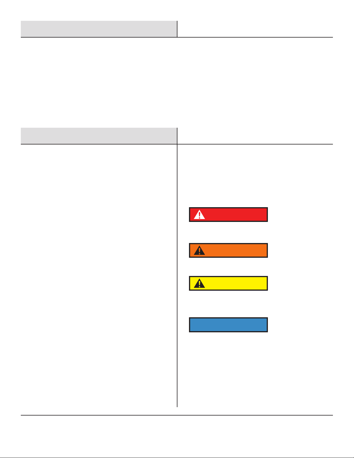
Throughout this manual and on generator decals you may see
one or more of the notices below. Safety Warnings alert you to
potential hazards that could cause death, injury, or damage to
property. The decals show one of four words "DANGER",
"WARNING", "CAUTION", and "NOTICE". Definitions are
as follows:
DANGER indicates an imminently hazardous situation which,
if not avoided, will result in death or serious injury.
WARNING indicates a potentially hazardous situation which,
if not avoided, could result in death or serious injury.
CAUTION indicates a potentially hazardous situation which,
if not avoided, may result in minor or moderate injury. It
may also be used to alert against unsafe practices.
Failure to follow the instruction may result in the damage
to your generator and other property.
Safety Warning.........................1
Safety Instructions......................2
Names of Components...................3
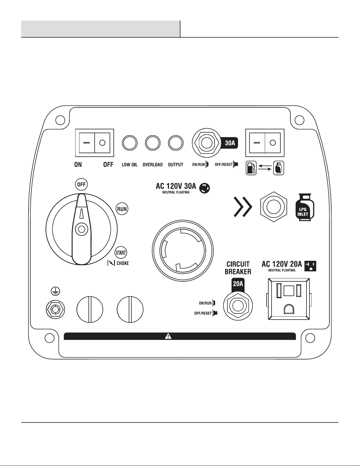
Control Panel ..........................4
Control Functions.......................5
Preparing Your Generator.................6
Starting up the Generator.................7
Shutting Down the Generator .............10
Using the Generator.....................10
Service and Maintenance................ 11
Storage and Transport ................. 13
Troubleshooting....................... 14
Technical Parameters .................. 15
Electrical Schematic ................... 16
DANGER
WARNING
CAUTION
NOTICE

2
Safety Instructions
Before operating your generator, you must read and
understand the Operator’s Manual and familiarize yourself
with the safe operation practices.
NEVER use a generator indoors! Exhaust
and Carbon Monoxide can KILL YOU in
minutes
Avoid running the generator in the rain or
very high, condensing humidity.
Never smoke or allow any heat source
near the generator while refueling it.
Always shut down the generator and allow
it to cool before refueling!
This is a portable generator, DO NOT
attempt to connect it to any mains panel
Make sure not to spill any gasoline and
wipe up any accidental spills at once.

3
Names of Components
Before operating your generator, you must read and understand the Operator’s Manual and familiarize yourself with the safe
operation practices.
Lifting Handle
Left Enclosure Control Panel
Recoil Start
Spark Plug Access
Rear Panel
Muffler
Fuel Tank Cap
FUEL SOURCECIRCUIT BREAKERINDICATOR LIGHTLOW IDLE
PARALLEL CONNECTION
TO AVOID DAMAGE, DO NOT CONNECT OR DISCONNECT PARALLEL CABLES WHILE THE UNIT IS RUNNING.
SELECTOR SWITCH
Oil Fill Access
Air Filter Access
Right Enclosure

4
Control Panel
FUEL SOURCECIRCUIT BREAKERINDICATOR LIGHTLOW IDLE
PARALLEL CONNECTION
TO AVOID DAMAGE, DO NOT CONNECT OR DISCONNECT PARALLEL CABLES WHILE THE UNIT IS RUNNING.
MULTI-SWITCH

5
Control Functions
Multi-Switch
OFF - Ignition circuit is off, the fuel valve is closed, the engine
will not run.
RUN – Ignition circuit is on, the fuel valve is open, the choke is
open, and the engine runs normally.
START (CHOKE) – (only used for cold starting) Ignition circuit is
on, fuel valve is open, choke is closed.
If the engine is hot, do not
use the choke.
Oil Indicator (Red)
When the engine oil level drops too low the engine will
automatically shut down and the oil alarm indicator illuminates.
The engine can be restarted only after the engine oil is filled
correctly.
Tip: If the engine will not start turn the Multi-Switch knob to "RUN"
position and pull recoil handle. If the oil indicator flashes a few
seconds, the oil volume is insufficient, fill oil to the dipstick high
mark and restart it.
Multi-Switch
NOTICE
INDICATOR LIGHT
INDICATOR LIGHT
INDICATOR LIGHT
Overload Indicator (Red)
When the overload indicator illuminates, the generator has
detected excess electrical load and the circuit breaker may
open (trip).
If the overload indicator illuminates and the generator has no
electrical output, perform the following:
①Disconnect all electrical loads then and shut down the
generator.
②Reduce total draw of electrical loads connected, to less than
rated output.
③Confirm there is no debris blocking the air inlet, correct as
necessary.
④Make sure all circuit breakers are pushed in
⑤Next, restart the engine and add electrical load in gradual steps
Tip: When using electrical equipment with high starting current
(such as compressors, saws, pumps, etc.), the overload indicator
may illuminate for a few seconds, this is normal.
AC Indicator (Green)
The AC indicator illuminates when electrical output is stable.
Energy Saving (Idle) Switch
1) "ON"
When energy saving switch is switched to "ON" position engine
speed is reduced when the generator is under light load. This
feature will reduce fuel consumption and noise.
LOW IDLE

6
Control Functions Preparing Your Generator
2) "OFF"
When the energy saving switch is set to the "OFF" position, the
engine will run at rated speed, regardless of connected load.
Fuel Tank Cap
Remove fuel tank cap by unscrewing it counterclockwise.
AC Circuit Breaker
If the total AC load exceeds the rated current, the AC circuit
breaker will open (trip) and the button will pop out. In this case
disconnect all loads, restart the generator and push in the AC
circuit breaker(s).
Grounding Terminal
If grounding is required by code or application, follow the
guidelines on page 10.
Engine Oil
Your generator ships without engine oil. Do not attempt to start the
generator without sufficient engine oil in the crankcase.
1)Place your generator on a flat, stable surface.
2)Unscrew the knob ①to remove oil access cover ②
3)Unscrew oil dipstick ③.
CIRCUIT BREAKER
Gasoline is highly flammable and toxic. You must read and
understand ALL safety instructions before fueling your
generator.
Do not overfill the fuel tank! Heat and vibration can cause
fuel to leak from an over-filled fuel tank.
After refueling, confirm that the fuel tank cap has been
tightened.
DANGER
1 2 3
4)Use a funnel to add 12 fluid ounces (0.35L) of 10w-30
engine oil to the crankcase, verify oil level with the dipstick.
5)Reassemble oil access cover and tighten the knob.
Pre-use inspection
Fuel
Check fuel level; add if necessary.
Oil
Check oil level; add if necessary. Check for any oil leaks.
Gasoline
Even when not in use the generator is potentially hazardous.
Follow the checklist below before starting the generator. If any
problems are found, do not use the generator until it has been
repaired by an authorized Pulsar Products Service Center.
NOTICE

7
Preparing Your Generator
2)Disconnect all electrical loads, including parallel cables from
the generator
3)Upper Left “Low Idle” rocker switch to ‘OFF’
4)Upper Right “Fuel Source” rocker switch to “GASOLINE”
5)Turn the Multi-Switch to ‘START’ (choke) to start a cold
engine
Starting The Generator
Tip: Turn the Multi-Switch to ‘RUN’ to restart a warm engine
Multi-Switch
After fueling, wipe up any gasoline residue with a soft cloth to
prevent damage to the plastic enclosures.
Fuel tank capacity: 1 US gallon
Propane (LPG)
Remove fuel tank cap and add gasoline to the red horizontal
line.
NOTICE
Maximum Fuel Level
Propane is highly flammable and potentially explosive. You
must read and understand ALL safety instructions before
connecting propane to your generator.
Never bring a propane tank inside the home or any
enclosed structure.
After connection check for leaks: Open the tank supply
valve, apply soapy water to the gas fittings and ensure
there are no bubbles.
Propane has an added odorant which makes unburned
propane smell like sulfur or rotten eggs. If you ever smell
this, close the propane tank valve at once; then find and
correct the problem before attempting to restart the
generator.
How to Start A Cold Engine with Gasoline
1)Place generator on a level surface
DANGER
FUELSOURCECIRCUITBREAKERINDICATORLIGHTLOWIDLE
PARALLELCONNECTION
TOAVOID DAMAGE, DO NOT CONNECT OR DISCONNECT PARALLEL CABLES WHILE THE UNIT IS RUNNING.
SELECTORSWITCH
STEP 1. Gently pull the recoil handle out until resistance
(engine compression) is felt
To prevent possible injury, follow these steps below for safe
recoil engine starting
CAUTION
FUEL SOURCELOW IDLE

8
Starting The Generator
With the engine started, make sure the Multi-Switch is in
the ‘RUN’ position, then set the “Low Idle” rocker switch
to your load-based preference
1)Place generator on a level surface
2)Disconnect all electrical loads, including parallel cables
from the generator
3)Upper Left “Low Idle” rocker switch to ‘OFF’
4)Upper Right “Fuel Source” rocker switch to propane
5)Connect the propane regulator to the propane tank
How to Start Cold Engine with Propane
6)Connect the propane hose to the front panel propane inlet;
tighten until snug
7)Open the propane tank valve, be aware of any smell of gas
and apply soapy water to the fittings to check for leaks. Only
proceed if there are no leaks
8)Turn the Multi-Switch to ‘START’ (choke) to start a cold
engine
9)Follow the three steps below for a safe recoil engine start
FUELSOURCECIRCUITBREAKERINDICATORLIGHTLOWIDLE
PARALLELCONNECTION
TOAVOID DAMAGE, DO NOT CONNECT OR DISCONNECT PARALLEL CABLES WHILE THE UNIT IS RUNNING.
SELECTORSWITCH
STEP 2. Let the recoil handle retract completely.
STEP 3. Grasp the top handle securely and pull the recoil
handle swiftly and completely; the engine should start.
FUEL SOURCELOW IDLE
Propane Tank
Propane Hose
LPG INLET
Tip: Turn the Multi-Switch to ‘RUN’ to restart a warm engine
MULTI-SWITCH
FUELSOURCECIRCUITBREAKERINDICATORLIGHTLOWIDLE
PARALLELCONNECTION
TOAVOID DAMAGE, DO NOT CONNECT OR DISCONNECT PARALLEL CABLES WHILE THE UNIT IS RUNNING.
SELECTORSWITCH
STEP 1. Gently pull the recoil handle out until resistance
(engine compression) is felt
To prevent possible injury, follow these steps below for safe
recoil engine starting
CAUTION
FUELSOURCECIRCUITBREAKERINDICATORLIGHTLOWIDLE
PARALLELCONNECTION
TOAVOIDDAMAGE, DO NOT CONNECT OR DISCONNECT PARALLEL CABLES WHILE THE UNIT IS RUNNING.
SELECTORSWITCH

9
Starting The Generator
With the engine started, make sure the Multi-Switch
is in the ‘RUN’ position, then set the “Low Idle” rocker
switch to your load-based preference.
Hot Restart on Propane - Special Note
When both gasoline and propane are present in the generator it
is recommended to start the generator on gasoline first, allow
the engine to stabilize then switch to propane.
Fuel source rocker switch to ‘GASOLINE’
Pull cord to start the engine, wait for the green light
OPEN the LPG valve completely
Fuel source switch to ‘LPG’
FUELSOURCECIRCUITBREAKERINDICATORLIGHTLOWIDLE
PARALLELCONNECTION
TOAVOID DAMAGE, DO NOT CONNECT OR DISCONNECT PARALLEL CABLES WHILE THE UNIT IS RUNNING.
SELECTORSWITCH
STEP 2. Let the recoil handle retract completely.
STEP 3. Grasp the top handle securely and pull the recoil
handle swiftly and completely; the engine should start.
CLOSED
OPEN
Ensure the LPG supply hose is securely attached and
Close the LPG valve completely
FUEL SOURCE
FUEL SOURCE
FUELSOURCECIRCUITBREAKERINDICATORLIGHTLOWIDLE
PARALLELCONNECTION
TOAVOIDDAMAGE, DO NOT CONNECT OR DISCONNECT PARALLEL CABLES WHILE THE UNIT IS RUNNING.
SELECTORSWITCH

10
Shutting Down the Generator
1)Turn the Multi-Switch to "OFF" position
2)After the generator has completely cooled down, remove
propane hose if applicable and store the generator in a
cool, dry, sheltered storage area.
3)Remove or consume all untreated gasoline if you plan to
store the generator longer than 3 months.
Connecting Loads to the Generator
①Start the engine
②Move Energy Saving switch to "OFF"
③Insert the plug(s) into AC outlet(s)
④Make sure that AC indicator is illuminated
⑤Switch on electrical equipment
Tip: If total load is less than half rated capacity, move the
Energy Saving Switch to ‘ON’. If the generator supplies power
to multiple devices plug-in those devices in from large to
small according to rated electrical load.
Range of Application
Before using the generator, please make sure that total load
is within rated load range of the generator, otherwise the
generator may be damaged.
FUELSOURCECIRCUITBREAKERINDICATORLIGHTLOWIDLE
PARALLELCONNECTI ON
TOAVOID DAMAGE, DO NOT CONNECT OR DISCONNECT PARALLEL CABLES WHILE THE UNIT IS RUNNING.
SELECTORSWITCH
Using the Generator
Operating Range of the Generator
• Ambient air temperature: 23F~104F (-5 ~ 40°C)
• Relative humidity <95%
• Recommended elevation <5,000 feet (1,500m) reduced
power at >3,300 feet (1,000 m)
Ideal Atmospheric Conditions
• Ambient air temperature: 77F (25°C)
• Relative humidity: 30%
• Atmospheric pressure: 1,000 millibars
Standard Deration:
• Every 9°F (5°C) increase in ambient air temperature will
reduce generator output by about 2%
• Every 30% of increase in relative humidity of air will reduce
generator output by about 1.5%
• Every 1,000 feet, (300m) elevation increase will reduce
generator output by about 3.5%
MULTI-SWITCH
Generator Grounding
If grounding is required by code or application, follow the
guidelines below. If you have ANY doubt, contact a licensed
electrician.
①Use grounding wire of minimum 12 gauge
②Connect one end of grounding wire to the grounding bolt on
the control panel.
③Connect the other end of the grounding wire to a suitable
ground point.

11
Service and Maintenance
Good maintenance is essential for safe, economical operation and long service life. The maintenance schedule is below:
Maintenance Cycle
Item
Engine oil
√
Replace
√
√
√
Air Cleaner
Element
Inspection
√
Clean
√
Replace
√
√
Clean
√
Clean - Adjust
√
Clean
√
Check - Adjust
√
Clean
√
Fuel Hose Inspection Every Two Years
Remove
Carbon
Deposit **
Check - Fill
** These tasks should be completed by an authorized Pulsar service center.
Every 125 hours
Cylinder Head, Piston
Fuel Tank and Fuel
Filter **
Valve Clearance **
Spark Arrester
Spark Plug
Carburetor Float
Bowl
Each
Week
Break-In
Maintenance at
1 Month or
20 Hours Use
Quarterly
Maintenance is
every 90 Days or
50 Hours Use
Annual
Maintenance
or 100 Hours
Use

12
Service and Maintenance
Spark Plug
①Remove access cover and spark plug boot.
②Use the (included) thin-wall T-socket wrench to remove the
spark plug by turning it counter-clockwise.
③Inspect spark plug for discoloration and remove carbon
deposits; replace if necessary.
④Adjust the gap 0.7~0.8mm.
Spark Plug # A5RTC
Gap: 0.7-0.8mm
⑤Install new or serviced spark plug in reverse order.
Spark Plug torque: 12.5 Nm; 110 in lbs.
Tip: If no torque wrench is available turn the spark plug ¼ - ½ turn
after the gasket contacts the cylinder head.
Adjustment of the Carburetor
This carburetor is not adjustable, only maintenance and cleaning
are possible. We strongly recommend leaving this work to an
authorized Pulsar Service Center.
Oil Change
①Raise the generator up on support blocks on a flat, stable
surface
②Unscrew the knob ①, to remove oil access cover
③Unscrew oil dipstick ③
④Place an oil pan under the engine, tilt the generator toward
the oil pan until all oil has drained; wipe up any spills.
⑤Refill crankcase with 12 ounces (0.35l) 10w-30 engine oil; check
with dipstick.
⑥Tighten oil dipstick, replace oil access cover, and tighten the
knob.
Air Filter
A dirty air filter can cause poor performance and engine damage.
Perform inspection and cleaning per the maintenance schedule
on page 11.
If the generator is used in high temperature or under high
load, change the oil every 25 hours.
If the generator is used in a dusty or abrasive environment,
service the air filter element every 10 hours; replace it
every 25 hours.
If you miss a maintenance cycle, perform the maintenance
as soon as possible per the table above.
Do not drain the oil immediately after turning off the generator;
allow it to cool completely before servicing it.
Shut down the engine and allow it to cool before performing
any service. Place the generator on a flat, stable surface.
Remove the spark plug boot to prevent accidental engine
start.
NEVER USE ANY GENERATOR INDOORS or in any poorly
ventilated area. Engine exhaust contains carbon monoxide
which can KILL you and others in the area.
NOTICE
DANGER
WARNING
①
③

13
Service and Maintenance
Storage and Transport
Air Filter
A dirty air filter can cause poor performance and engine damage.
Perform inspection and cleaning per the maintenance schedule
on page 11.
1. Remove screws ③, to remove air filter housing ④;
2. Remove foam filter element ⑤;
3. Clean foam filter element with a mild soap solution, rinse
well and let it dry
4. Place a few drops of engine oil on the foam filter element
and squeeze gently to distribute the oil film evenly
5. Reinstall the air filter element in reverse order.
1. Remove fuel tank cap and fuel tank filter screen.
2. Clean fuel tank filter screen with mild soap and hot water.
3. Allow filter screen dry thoroughly and replace it in the fuel tank.
4. Replace fuel cap tightly.
Generator Long Term Storage
1. Turn the Multi-Switch to "OFF" and allow generator to cool
completely.
2. Remove the spark plug boot to prevent accidental engine
start.
Fuel Filter Screen
①
②
⑤
③
④
NEVER approach the generator while smoking or with any ignition
source!
DANGER
MULTI-SWITCH

14
Storage and Transport
Troubleshooting
4). Remove bolts and right service access panel
5). Using a Phillips screwdriver, open fuel drain valve on the
carburetor and drain remaining fuel into an approved
gasoline container.
6). Tighten fuel drain valve.
7). Change engine oil per page 12
8). Remove spark plug and instill one teaspoon (5ml) new engine
oil into combustion chamber. Pull the recoil a few times,
to distribute oil, then reinstall the spark plug.
9). Replace right service access panel.
10). Gently pull recoil handle until you feel resistance, indicating
the intake and exhaust valves are closed.
11). Store the generator in a clean and dry area.
Generator Transport
Pulsar Products recommends that the generator should be
empty of fuel when transported unless the generator is secured
in an open truck bed and secured from tipping. In this case,
follow the guidelines below:
• Do not completely fill the fuel tank, leave some expansion space.
• Do not run the generator while transporting.
• Protect from direct sunlight.
• Do not transport the generator across rough terrain.
Engine No-Start
Fuel System
1) There is no fuel.
2) Fuel doesn’t reach combustion chamber
3) Contaminated or old fuel
4) There is debris in the fuel valve
5) Carburetor is fouled, service carburetor
Insufficient Engine Oil
Oil level is too low
Ignition System
1) Verify Multi-Switch is at ‘RUN’ or CHOKE’
2) No spark from ignition coil failure
3) Spark plug is fouled, service it per page 12
1) Worn out engine
2) Cylinder head bolts have loosened, have an authorized Pulsar
Service Center re-torque them properly
3) Head gasket leak
Engine Runs, No Power Output
1) Ensure all circuit breakers are pushed in
2) If generator was exposed to moisture or rain, move it to a dry
location for several hours
3) Vibration may have caused one or more connectors to loosen over
time, check with Pulsar Technical Support for guidance
4) Check electrical receptacles for damage
5) Generator may be overloaded; remove load, shut down, then
restart the engine
Low Compression

15
Technical Parameters
Item Parameter
Engine
Engine Model 148F/P -2 164F/P
Engine Type
Bore size × Stroke (mm) 48.6×43
Displacement (cc) 79.7 145
Compression Ratio 8.7± 0.2 8.7± 0.2
Cylinder Head OHV OHV
Cooling Mode Forced Air Forced Air
Output Power (kW/r/min) 2.1/4500 3.8/4650
Starting Method Recoil
Fuel Tank Volume
Fuel Type and Grade
Lubricating Oil Capacity
Lubricating Oil Model
Lubrication Mode Splash Lubrication Splash Lubrication
Noise dB (at 7m) 62 63
Generator
Rated Power (kW) 1.8 2.8
Rated Voltage (V) 120 120
Rated Frequency (Hz) 60 60
Rated Power Factor 1 1
Phase Number Single Phase Single Phase
Configuration
Motor Brushless (Permanent Magnet)
Voltage Regulation Inverter Regulation
Frequency Regulation Inverter Regulation
Overall Dimension 18.9”x11.5”x17” 18.9”x11.5”x17”
Net Weight
Single-cylinder, four-stroke, air-cooled, overhead valve,
tilted 25º of the center of gasoline engine cylinder
64×45
1.1 Gallon 1 Gallon
Gasoline or Propane
(0.35L) (0.45L)
SAE 10w-30 SAE 10w-30
40lbs. (18kg) 46lbs. (21kg)

16
Electrical Schematic
120V, 60Hz Electrical Schematic
Table of contents
Other Pulsar Portable Generator manuals

Pulsar
Pulsar PG7750B User manual

Pulsar
Pulsar PG10000 User manual

Pulsar
Pulsar PG2200 User manual

Pulsar
Pulsar PG7000DOF User manual

Pulsar
Pulsar PG4000iSR User manual

Pulsar
Pulsar PG15KVTW User manual

Pulsar
Pulsar G10KBN User manual

Pulsar
Pulsar PG7750BCO User manual

Pulsar
Pulsar PG3500MR User manual

Pulsar
Pulsar PGD40iSCO User manual

Pulsar
Pulsar PG2000iS User manual

Pulsar
Pulsar PGD105TiSCO User manual

Pulsar
Pulsar PGD95BiSCO User manual

Pulsar
Pulsar PG7500B User manual

Pulsar
Pulsar PG10000BRCO User manual

Pulsar
Pulsar PG2000 User manual

Pulsar
Pulsar 5250B User manual

Pulsar
Pulsar PG6580E User manual

Pulsar
Pulsar PG2300iS User manual

Pulsar
Pulsar PG5250B User manual