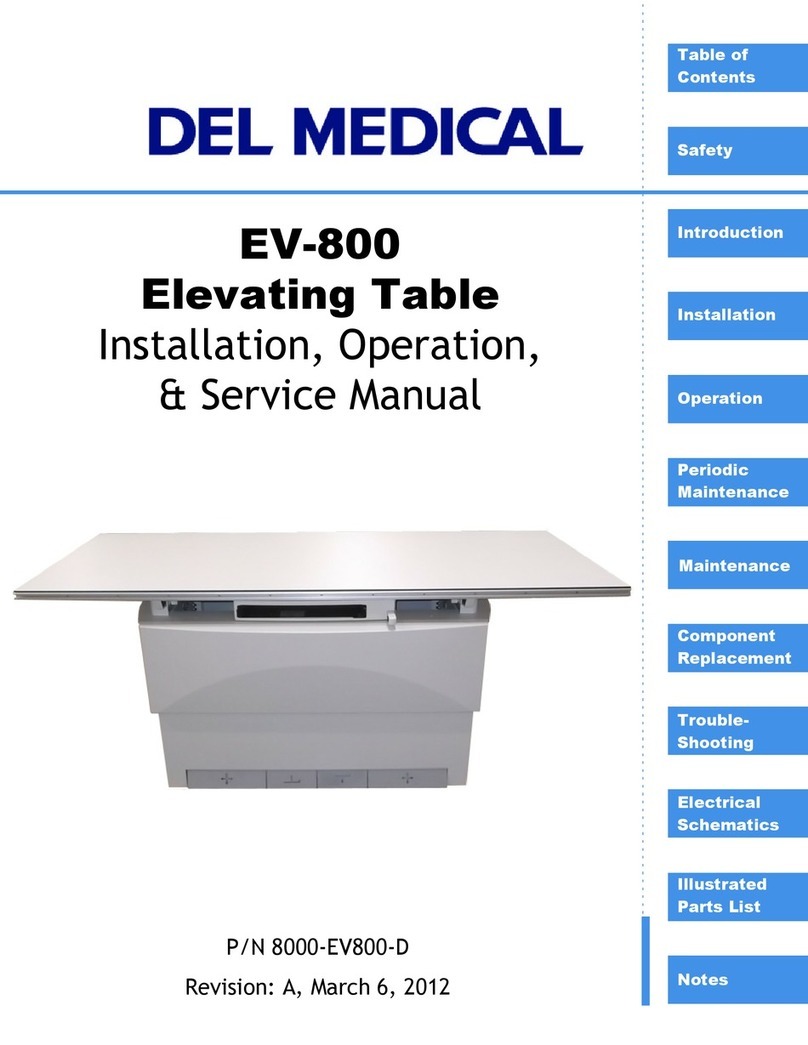
Del Medical EV-650 Manual

EV-650
Elevating Table
Installation, Operation &
Service Manual
P/N 8000-EV-650-D
Revision: A, July 2005
EV-650

Copyright 2005, Del Medical Systems. All rights reserved.
This document is the property of Del Medical Systems and contains confidential and proprietary
information owned by Del Medical Systems. Any unauthorized copying, use or disclosure of it
without the prior written permission of Del Medical Systemsis strictly prohibited.
Attention: Consult Accompanying Documents - As Applicable
Del Medical Systems Group
11550 West King Street Phone:1-847-288-7000
Franklin Park, IL Fax:1-847-288-7011
60131-1330 USA Toll Free:1-800-800-6006
www.delmedical.com

Rev A i
Table of Contents
Safety Information
Introduction . . . . . . . . . . . . . . . . . . . . . . . . . . . . . . . . . . . . . . . . . . . . . . . ii-1
Statement of Liability . . . . . . . . . . . . . . . . . . . . . . . . . . . . . . . . . . . . . . . ii-2
Definitions . . . . . . . . . . . . . . . . . . . . . . . . . . . . . . . . . . . . . . . . . . . . . . . . . ii-3
Safety Conventions Used in this Manual . . . . . . . . . . . . . . . . . . . . . . . ii-4
Warning Statements . . . . . . . . . . . . . . . . . . . . . . . . . . . . . . . . . . . . . ii-4
Caution Statements . . . . . . . . . . . . . . . . . . . . . . . . . . . . . . . . . . . . . ii-5
Equipment Safety Guidelines . . . . . . . . . . . . . . . . . . . . . . . . . . . . . . . . ii-6
Emergency Stop Button (For Service Technicians Only). . . . . . . . . . . . . . ii-9
Chapter 1 — Introduction
1.1 Introduction . . . . . . . . . . . . . . . . . . . . . . . . . . . . . . . . . . . . . . . . . . . . 1-1
1.2 Description . . . . . . . . . . . . . . . . . . . . . . . . . . . . . . . . . . . . . . . . . . . . . 1-1
1.3 Dimensions . . . . . . . . . . . . . . . . . . . . . . . . . . . . . . . . . . . . . . . . . . . . . 1-2
1.4 Minimum Space Requirements . . . . . . . . . . . . . . . . . . . . . . . . . . . . 1-4
1.5 Specifications . . . . . . . . . . . . . . . . . . . . . . . . . . . . . . . . . . . . . . . . . . . 1-5
1.6 Abbreviations . . . . . . . . . . . . . . . . . . . . . . . . . . . . . . . . . . . . . . . . . . . 1-6
1.7 Optional Accessories . . . . . . . . . . . . . . . . . . . . . . . . . . . . . . . . . . . . . 1-7
Chapter 2 — Installation
2.1 Installation Instructions . . . . . . . . . . . . . . . . . . . . . . . . . . . . . . . . . . 2-1
Chapter 3 — Operation
3.1 Safety Precautions . . . . . . . . . . . . . . . . . . . . . . . . . . . . . . . . . . . . . . . 3-1
3.2 Operation Specifications . . . . . . . . . . . . . . . . . . . . . . . . . . . . . . . . . . 3-4
3.3 Controls . . . . . . . . . . . . . . . . . . . . . . . . . . . . . . . . . . . . . . . . . . . . . . . . 3-5
Down Pedal . . . . . . . . . . . . . . . . . . . . . . . . . . . . . . . . . . . . . . . . . . . . 3-5
Up Pedal . . . . . . . . . . . . . . . . . . . . . . . . . . . . . . . . . . . . . . . . . . . . . . . 3-6
Unlock Pedals . . . . . . . . . . . . . . . . . . . . . . . . . . . . . . . . . . . . . . . . . . 3-6
Bucky Carriage Lock Release . . . . . . . . . . . . . . . . . . . . . . . . . . . . . 3-6
Power Indicator . . . . . . . . . . . . . . . . . . . . . . . . . . . . . . . . . . . . . . . . . 3-6
3.4 Cassette Tray Removal . . . . . . . . . . . . . . . . . . . . . . . . . . . . . . . . . . . 3-7
3.5 Emergency Stop Button (For Service Technicians Only) . . . . . . . 3-8

EV-650 Elevating Table Installation, Operation and Service Manual
ii Rev A
Chapter 4 — Periodic Maintenance
4.1 Periodic Maintenance Schedule . . . . . . . . . . . . . . . . . . . . . . . . . . . . 4-1
4.2 Cleaning External Surfaces . . . . . . . . . . . . . . . . . . . . . . . . . . . . . . . . 4-2
4.3 Greasing Lift Racks . . . . . . . . . . . . . . . . . . . . . . . . . . . . . . . . . . . . . . 4-4
4.4 Checking & Adjusting Chain Tension . . . . . . . . . . . . . . . . . . . . . . 4-6
Chapter 5 — Maintenance
5.1 Introduction . . . . . . . . . . . . . . . . . . . . . . . . . . . . . . . . . . . . . . . . . . . . 5-1
5.2 Removing Front Panels . . . . . . . . . . . . . . . . . . . . . . . . . . . . . . . . . . . 5-2
5.3 Replacing Fuses F2, F3, & F4 . . . . . . . . . . . . . . . . . . . . . . . . . . . . . . 5-4
5.4 Replacing Fuses F1, FL1, & FL2 . . . . . . . . . . . . . . . . . . . . . . . . . . . . 5-5
5.5 Replacing 24V Power Supply Board Fuse. . . . . . . . . . . . . . . . . . . . 5-6
5.6 Replacing DC Motor Speed Control Fuse . . . . . . . . . . . . . . . . . . . . 5-7
5.7 Manually Raising & Lowering Table Top . . . . . . . . . . . . . . . . . . . 5-9
5.8 Changing Input Voltage from 120V to 240V . . . . . . . . . . . . . . . . 5-12
5.9 Changing Input Voltage from 240V to 120V . . . . . . . . . . . . . . . . 5-15
5.10 Changing Elevation Restart Mode . . . . . . . . . . . . . . . . . . . . . . . . 5-18
5.11 Adjust Table Elevation Mid-Point Height. . . . . . . . . . . . . . . . . . 5-21
5.12 Testing & Adjusting Collision Avoidance Switches . . . . . . . . . 5-23
Chapter 6 — Component Replacement
6.1 Introduction . . . . . . . . . . . . . . . . . . . . . . . . . . . . . . . . . . . . . . . . . . . . 6-1
6.2 Removing Front Panels . . . . . . . . . . . . . . . . . . . . . . . . . . . . . . . . . . . 6-2
6.3 Replacing Main Chassis . . . . . . . . . . . . . . . . . . . . . . . . . . . . . . . . . . . 6-4
6.4 Replacing Foot Treadle Assembly . . . . . . . . . . . . . . . . . . . . . . . . . . 6-6
6.5 Repacing K301 Relay . . . . . . . . . . . . . . . . . . . . . . . . . . . . . . . . . . . . . 6-8
6.6 Replacing Drive Motor Assembly . . . . . . . . . . . . . . . . . . . . . . . . . . 6-9
6.7 Replacing 24V Power Supply Board . . . . . . . . . . . . . . . . . . . . . . . 6-11
6.8 Replacing Motor Controller Board. . . . . . . . . . . . . . . . . . . . . . . . . 6-13
6.9 Replacing DC Motor Speed Control. . . . . . . . . . . . . . . . . . . . . . . . 6-15
6.10 Replacing DC Motor Speed Control Relay . . . . . . . . . . . . . . . . . 6-17
6.11 Replacing Emergency Stop Switch. . . . . . . . . . . . . . . . . . . . . . . . 6-19
6.12 Replacing Treadle Switch . . . . . . . . . . . . . . . . . . . . . . . . . . . . . . . 6-20
6.13 Replacing Left-Right Table Brake. . . . . . . . . . . . . . . . . . . . . . . . . 6-21
6.14 Replacing Height Limit Switches . . . . . . . . . . . . . . . . . . . . . . . . . 6-25
6.15 Replacing Bucky Brake. . . . . . . . . . . . . . . . . . . . . . . . . . . . . . . . . . 6-27
6.16 Replacing Collision Avoidance Switches . . . . . . . . . . . . . . . . . . 6-32
6.17 Replacing K101 & 102 Relays . . . . . . . . . . . . . . . . . . . . . . . . . . . . 6-35

EV-650 Elevating Table Installation, Operation and Service Manual
Rev A iii
6.18 Replacing In-Out Table Brake. . . . . . . . . . . . . . . . . . . . . . . . . . . . 6-37
Chapter 7 — Troubleshooting
7.1 Introduction. . . . . . . . . . . . . . . . . . . . . . . . . . . . . . . . . . . . . . . . . . . . . 7-1
7.2 Troubleshooting Index & Charts . . . . . . . . . . . . . . . . . . . . . . . . . . . 7-2
7.3 Schematic Troubleshooting. . . . . . . . . . . . . . . . . . . . . . . . . . . . . . . 7-10
7.3.1 Component Listing . . . . . . . . . . . . . . . . . . . . . . . . . . . . . . . . . 7-13
7.3.2 Main Chassis Location/Layout . . . . . . . . . . . . . . . . . . . . . . 7-15
7.3.3 Teadle Switch Location/Layout . . . . . . . . . . . . . . . . . . . . . . 7-17
7.3.4 Limit Switch Location/Layout . . . . . . . . . . . . . . . . . . . . . . . 7-18
7.3.5 Bucky Lock Release Location . . . . . . . . . . . . . . . . . . . . . . . . 7-19
7.3.6 Various Switch Location . . . . . . . . . . . . . . . . . . . . . . . . . . . . 7-20
7.3.7 Bucky Coil Locks. . . . . . . . . . . . . . . . . . . . . . . . . . . . . . . . . . . 7-21
7.4 Main Chassis Connector Pinout Definitions . . . . . . . . . . . . . . . . 7-22
Chapter 8 — Electrical Schematics
8.1 Electrical Schematics . . . . . . . . . . . . . . . . . . . . . . . . . . . . . . . . . . . . . 8-1
Chapter 9 — Illustrated Parts List
9.1 Ordering Parts . . . . . . . . . . . . . . . . . . . . . . . . . . . . . . . . . . . . . . . . . . 9-1
To Order by Telephone . . . . . . . . . . . . . . . . . . . . . . . . . . . . . . . . . . 9-1
To Order by Fax . . . . . . . . . . . . . . . . . . . . . . . . . . . . . . . . . . . . . . . . 9-1
9.2 How to Use This Parts List . . . . . . . . . . . . . . . . . . . . . . . . . . . . . . . . 9-2
9.3 Commonly Ordered Parts List . . . . . . . . . . . . . . . . . . . . . . . . . . . . . 9-2
9.4 Overall Elevating Table Assembly (110-5047) . . . . . . . . . . . . . . . . 9-4
9.5 Inner Frame Assembly (112-5343G1) . . . . . . . . . . . . . . . . . . . . . . 9-14
9.6 Drive Frame Assembly (112-5053G1) . . . . . . . . . . . . . . . . . . . . . . 9-16
9.7 Drive Shaft Assembly (112-0322G1) . . . . . . . . . . . . . . . . . . . . . . . 9-18
9.8 Lower Frame Assembly (112-5050G1) . . . . . . . . . . . . . . . . . . . . . 9-20
9.9 Upper Frame Assembly (112-5051G1) . . . . . . . . . . . . . . . . . . . . . 9-22
9.10 SID/Limit Switch Cam Plate Assembly (112-5239G1) . . . . . . . 9-24
9.11 Treadle Channel Assembly (112-5043G2) . . . . . . . . . . . . . . . . . 9-25
9.12 Main Chassis Assembly (120-5018G1) . . . . . . . . . . . . . . . . . . . . 9-26
9.13 Upper Shroud Assembly (112-5056G1) . . . . . . . . . . . . . . . . . . . 9-28
9.14 Bucky Carriage Assembly (112-5242G1) . . . . . . . . . . . . . . . . . . 9-30
9.15 Support Bracket Assembly (Right Hand) (112-5240G1) . . . . . 9-34
9.16 Support Bracket Assembly (Left Hand) (112-5241G1) . . . . . . . 9-36

EV-650 Elevating Table Installation, Operation and Service Manual
iv Rev A
9.17 Transverse Lock Assembly (122-5053) . . . . . . . . . . . . . . . . . . . . 9-38
9.18 Collision Avoidance Assembly (112-5040G1 & 112-5040G2) . 9-39
9.19 SID/Limit Switch Assembly (112-5244G1) . . . . . . . . . . . . . . . . 9-40
9.20 Cable Chain Assembly (112-5253G1) . . . . . . . . . . . . . . . . . . . . . 9-41
9.21 Bucky Cover/Harness Assembly (112-5058G1) . . . . . . . . . . . . 9-42
9.22 Elevating Table Options & Accessories . . . . . . . . . . . . . . . . . . . 9-43

Introduction ii-1
i
Safety Information
Introduction
The policy of Del Medical Systems Group is to manufacture X-ray
equipment that meet high standards of performance and reliability. We
enforce strict quality control techniques to eliminate the potential for
defects and hazards in our products.
The intended use of this equipment is to provide an adjustable elevating
platform for positioning of a patient with respect to an X-ray source for the
purpose of acquiring X-ray images of the desired parts of a patient’s
anatomy. Use of this equipment in any other fashion may lead to serious
personal injury.
The safety guidelines provided in this section of the manual are intended
to educate the operator on all safety issues in order to operate and
maintain the table in a safe manner.

EV-650 Elevating Table Installation, Operation & Maintenance Manual
ii-2 Statement of Liability
Statement of Liability
To prevent excess radiation exposure to patient and operator from either
primary or secondary radiation, this table must be operated and serviced
by trained personnel who are familiar with the safety precautions
required. While this table has been designed for safe operation, improper
operation or carelessness may result in serious injury or damage to
equipment. The manufacturer or its agents and representatives assume no
responsibility for the following:
1Injury or danger to any person from x-ray exposure.
2Overexposure due to poor technique selection.
3Injury or danger from improper use of the elevator function.
4Problems or hazards resulting from failure to maintain the equipment
as specified in the Installation chapter.
5Equipment which has been tampered with or modified. Del Medical
Systems Group is not liable for any damage or injury arising from
failure to follow the instructions and procedures provided within the
manuals or associated informational material, or from user failure to
use caution when installing, operating, adjusting, or servicing this
equipment. Del Medical Systems Group is not liable for damage or
injury arising from the use of this product for any other use than that
intended by the manufacturer.

EV-650 Elevating Table Installation, Operation & Maintenance Manual
Definitions ii-3
Definitions
The table below defines the meaning of various symbols used on labels on
the machine.
This warning symbol is used to indicate a
potential hazard to operators, service per-
sonel or equipment. It indicates a requirement
to refer to the accompanying documentation
for details.
This symbol indicates that there is accessible
dangerous voltage.
This symbol identifies a protective earth termi-
nal.
This symbol states that this product is catego-
rized as Type B.
Type B is defined as:
Equipment providing a particular degree of
protection against electric shock, particularly
regarding allowable leakage currents and reli-
ability of the protective earth connection (if
present).

EV-650 Elevating Table Installation, Operation & Maintenance Manual
ii-4 Safety Conventions Used in this Manual
Safety Conventions Used in this Manual
Specific safety information is listed in this manual in the form of
WARNING and CAUTION statements. Pay close attention to these
statements - they contain important information on avoiding potential
hazards to you or the equipment.
Warning Statements
• are used to indicate hazards or unsafe practices which COULD result
in severe personal injury or death.
• appear in bold type.
• have a triangular symbol with an exclamation point above the text.
• are preceded by the word Warning.
• are always found before the step or piece of information to which they
refer to.
• look like the following example:
Warning
Turn off electrical power to table at power source before servicing
table. Also, make sure that power source is locked out and tagged
“Table Being Serviced” before servicing table. You could get
seriously shocked or burned if you do not.

EV-650 Elevating Table Installation, Operation & Maintenance Manual
Safety Conventions Used in this Manual ii-5
Caution Statements
• are used to indicate hazards or unsafe practices which could result in
minor personal injury or product or property damage.
• appear in bold type.
• have a triangular symbol with an exclamation point above the text.
• are preceded by the word Caution.
• are always found before the step or piece of information to which they
refer to.
• look like the following example:
Caution
The lock nut must be drawn up tightly against the idler sprocket
mounting bracket to ensure that screw does not loosen when table
is in use.

EV-650 Elevating Table Installation, Operation & Maintenance Manual
ii-6 Equipment Safety Guidelines
Equipment Safety Guidelines
The following warnings and cautions are specific to the EV-650 Elevating
Table. Read them carefully - some of them are not obvious to typical
equipment use.
Warning
Turn off electrical power to table at power source before servicing
table. Also, make sure that power source is locked out and tagged
“Table Being Serviced” before servicing table. You could get
seriously shocked or burned if you do not.
Warning
Do not place any objects within the vertical motion area above or
below table. Objects in such areas can present crush hazards for
the patient or operator and can also damage the table. See areas
shown shaded in Figure below.
The table is equipped with a collision avoidance switch for
downward motion. This switch, however, is designed to protect
the table, not the operator or patient from a collision. The
downward motion of the table will stop if the table encounters 100
lbs (44kgs) of upward force.

EV-650 Elevating Table Installation, Operation & Maintenance Manual
Equipment Safety Guidelines ii-7
Warning
Make sure that the operator or the patient does not touch the table
unlock pedals when the patient is getting on or off table. This may
cause the patient to fall off the table and cause serious injury. See
Figure below.
Warning
Do not operate the table in an explosive atmosphere (such as
anesthetic gas). Doing so can cause an explosion or fire hazard
causing serious injury.
Unlock Pedals

EV-650 Elevating Table Installation, Operation & Maintenance Manual
ii-8 Equipment Safety Guidelines
Warning
All of the movable assemblies and parts of this equipment should
be operated with care and routinely inspected in accordance with
the manufacturer’s recommendations contained in this manual.
Only properly trained and qualified personnel should be
permitted access to any internal parts. Live electrical terminals are
deadly; be sure line disconnect switches are opened and other
appropriate precautions are taken before opening access doors,
removing enclosure panels, or attaching accessories.
Do not remove flexible high tension cables from X-ray tube
housing or high-tension generator and/or access covers from X-ray
generator until the main and auxiliary power supplies have been
disconnected.
For all components of the equipment, protective earthing means
must be provided in compliance with the national regulations.
Warning
This table is intended to be used as part of a system for the
intended generation of X-rays for medical diagnosis.
X-rays generate a potential risk for both patients and operators.
For this reason, the application of X-rays for a given medical
purpose must aim at the minimization of radiation exposition to
any persons.
Those persons responsible for the application must have the
specific knowledge according to legal requirements and
regulations and must establish safe exposure procedures for this
kind of systems.
Those persons responsible for the planning and installation of this
equipment must observe the national regulations.

EV-650 Elevating Table Installation, Operation & Maintenance Manual
Emergency Stop Button (For Service Technicians Only) ii-9
Emergency Stop Button (For Service Technicians
Only)
There is an Emergency Stop Button located in the table’s base that can be
pressed to stop the motion of the table in an emergency. It is meant only to
be used by technicians who are troubleshooting the table.
If the button is pressed, it must be turned in the direction of the arrows on
the button until the button pops back up in order to reset the button.
Otherwise, the table cannot be restarted. See Figure below for location of
button.
Warning
The Emergency stop button DOES NOT turn off all power to the
table. There may still be lethal voltages present on the main
chassis and throughout the table when this button is turned off.
These voltages come from sources outside the table ( i.e. generator,
wallstand, etc.) that are connected to the table.
Emergency Stop Button
Emergency Stop Button

EV-650 Elevating Table Installation, Operation & Maintenance Manual
ii-10 Emergency Stop Button (For Service Technicians Only)

Rev A 1.1 Introduction 1-1
1
Introduction
1.1 Introduction
This manual provides installation, operation and service information for
the EV-650 Elevating Table. This manual also includes a spare parts list for
the table.
1.2 Description
The EV-650 elevating radiographic table is designed for general purpose
radiography and is ideally suited for modern hospitals, urgent care
centers, clinics and private practices.
The EV-650 features a four-way, floating table top which provides 40” (102
cm) of longitudinal travel and 9.0” (23 cm) of transverse travel. It has a
motor driven telescopic base which permits the tabletop to be lowered to
within 22” (55.9 cm) of the floor and raised to a maximum height of 34”
(86.4 cm) above the floor.
Electro-mechanical locks maintain the desired position. The position of the
table top can be raised and lowered, and the locks released by operating
the foot pedals. The table’s bucky can also be repositioned by pressing the
pushbutton.

EV-650 Elevating Table Installation, Operation & Maintenance Manual
1-2 1.3 Dimensions Rev A
1.3 Dimensions
Figure 1-1. Dimensions
86.6”
220.0cm
21.7” Min
55.2cm
33.7” Max
85.7cm
52.9”
134.3cm
26.4”
67.2cm
24.4”
62.0cm
24.9”
63.2cm
31.9”
81.0cm
4.25”
10.8cm
12.1”
30.7cm
4.25”
10.8cm
13.7”
34.9cm
Rad. Center
Rad. Center
Table Center
Table Center
30.5”
77.5cm
Film
Plane

EV-650 Elevating Table Installation, Operation & Maintenance Manual
Rev A 1.3 Dimensions 1-3
Figure 1-2. Table Foot Print
Caution
Do not drill equipment mounting holes in pre-tensioned or post
tensioned concrete floors before determining the location of the
tensioned wire ropes. Consult with customer or responsible
project engineer to locate and avoid drilling through wire rope.
Cutting through tensioning cables can cause severe structural
damage.
Note: Bolt hole locations and overall base
dimensions are symetrical unless
otherwise dimensioned.
Total Area of Base 8.8 Sq./Ft. (.818 Sq. M)
Floor Loading 56.8 Lbs/Sq. Ft. (277.5 Kg/Sq. M)
Bolt Hole Diameter .75” (19mm) 4 Locations
52 7/8”
1344mm
162mm
42mm
6 7/16”
1 11/16”
50mm
2”
355mm
14”
Cable Access
25”
634mm
670mm
26 3/8”
Radiographic
25mm
1”
15 3/4”
400mm
9mm
3/8”
1223mm
48 3/16”
8” (203mm) X
8” (203mm)
Centerline
5 1/8”
130mm
Head End Foot End
Base Thickness
16 ga. C.R.S. .059” (1.5mm)

EV-650 Elevating Table Installation, Operation & Maintenance Manual
1-4 1.4 Minimum Space Requirements Rev A
1.4 Minimum Space Requirements
Figure 1-3. Plan View (Top View) of Minimum Space Requirements
Front
Minimum 12” (30 cm) Side & Rear Hazard-Free
Table Top Range of Motion - 125” X 40” (317 cm X 102cm)
Table Base - 52 7/8” X 25” (134.4 cm X 63.4 cm)
Frontal space requirements are
site specific based on clinical
needs (i.e. wheel chair, gurney
accessibility requirements).
Buffer Zone Required Beyond Table Range -137” X 52” (348 cm X 132 cm)
40” (102 cm) 40” (102 cm)
9” (23 cm)
6” (15 cm)
Table of contents
Other Del Medical Medical Equipment manuals
Popular Medical Equipment manuals by other brands
Lowenstein Medical
Lowenstein Medical JOYCEeasy Instructions for use
ARJO HUNTLEIGH
ARJO HUNTLEIGH alpha active 4 Quick reference guide
ARJO HUNTLEIGH
ARJO HUNTLEIGH Prelude Instructions for use

Ama Tech
Ama Tech I-ABSLFH Instructions for use

QT Medical
QT Medical QT ECG Recorder user manual
Avantik
Avantik QS11 Quick reference guide
