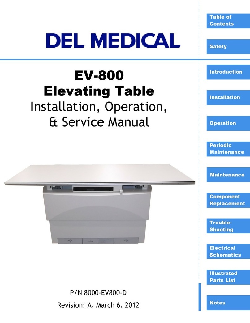
Del Medical EV200 User manual

©Del Medical Imaging June 28, 2002 page i of 31 pages
THIS DOCUMENT CONTAINS
INSTALLATION, MAINTENANCE,
AND OPERATION INFORMATION
- DO NOT DISCARD -
Del Medical Imaging Corporation
11550 W. King Street
Franklin Park, IL 60131
Tel: 847-288-7000
Fax: 847-288-7010
Manual Part Number 8000-8680R Revision D June 28, 2002
8000-8680R
EV200 ELEVATING TABLE
MODEL 8680R

©Del Medical Imaging June 28, 2002 page ii of 31 pages
MANUAL IMPROVEMENT RECOMMENDATION
We at Del Medical Imaging Corporation are most
interested in improving the quality of the Technical
Documentation we provide. Please identify any
improvements or corrections and fax them to our
Technical Publications Department.
Name________________________________________________
Dealership____________________________________________
Manual Part Number____________________________________
Device Name__________________________________________
Recommendation or Correction_____________________________________
________________________________________________________________
________________________________________________________________
________________________________________________________________
________________________________________________________________
________________________________________________________________
________________________________________________________________
________________________________________________________________
________________________________________________________________
Technical Support (847) 288-7000
Fax (847) 288-7011

©Del Medical Imaging June 28, 2002 page iii of 31 pages
Manual Revision History
Manual Part Number: 8000-8680
Revision Date Description of Changes
A
B 10/1/92
C 7/29/93
D 6/28/02
Addition of collision sensor assembly, schematic update, document
revised and converted to standardized manual format

EV200 Elevating Table Revision D Table of Contents
©Del Medical Imaging June 7, 2002 page iv of 31 pages
Table of Contents
INTRODUCTION .............................................................................................................5
SAFE OPERATION ..........................................................................................................5
DESCRIPTION..................................................................................................................5
BRH COMPLIANCE..........................................................................................................6
OPERATION....................................................................................................................7
SAFETY............................................................................................................................7
TABLE CONTROLS .........................................................................................................7
FOOT PEDAL SYMBOLS AND FUNCTIONS..................................................................7
REQUIRED PREVENTATIVE MAINTENANCE ...............................................................9
USER SERVICE AND MAINTENANCE ...........................................................................9
PRE INSTALLATION ....................................................................................................10
GENERAL SAFETY PROCEDURES .............................................................................10
MEASURES AND WEIGHTS INCL. PACKING MATERIAL (inch (mm))......................10
WEIGHT OF COMPONENTS .........................................................................................10
MEASURES OF COMPONENTS (inch (mm))...............................................................10
COMPONENT DESIGNATIONS.....................................................................................11
SELECTING EQUIPMENT LOCATION..........................................................................12
TABLE MOUNTING HOLES...........................................................................................13
MAINS CONNECTION DATA.........................................................................................13
INSTALLATION.............................................................................................................14
TOOLS, EQUIPMENT AND MATERIALS......................................................................14
UNPACKING AND HANDLING......................................................................................14
ALTERNATE METHOD OF MOUNTING TABLE TOP IN SMALL ROOMS..................20
TEST AND CALIBRATION ...........................................................................................22
SID SWITCH POSITIONING...........................................................................................22
ADJUSTMENT OF THE COLLISION SENSOR SWITCH..............................................22
SETTING THE ADJUSTABLE TENSION BEARING ASSEMBLIES.............................24
VERIFY PROPER OPERATION OF COLLISION SWITCHES ......................................24
SCHEMATICS...............................................................................................................25
RENEWAL PARTS........................................................................................................26
PERIODIC MAINTENANCE..........................................................................................28
MECHANICAL AND ELECTRICAL TESTS...................................................................28

EV200 Elevating Table Revision D Introduction
©Del Medical Imaging June 7, 2002 page 5 of 31 pages
INTRODUCTION
The operating instructions for the EV 200 Elevating Table are included in the Operation
chapter of this manual. Further instructions to installers and field service personnel are
included in the remaining chapters of this manual. This table may be used with most tube
stands.
IMPORTANT
This equipment may cause injury if used improperly. The instructions contained in this
manual must be read and followed when operating the EV 200 elevating table.
SAFE OPERATION
To prevent excessive radiation exposure to patient and operator from either primary or
secondary radiation, and to prevent possible harm, this table must be operated and
serviced by trained personnel who are familiar with the required safety precautions. While
this table has been designed for safe operation, improper or careless operation can result
in an unsafe condition. Del Medical Imaging Corporation or its agents and representatives
assume no responsibility for:
1. Injury or danger to any person from x-ray exposure.
2. Overexposure due to poor technique selection.
3. Injury or danger from improper use of the elevator function.
4. Problems or hazards resulting from failure to maintain the equipment as outlined in
the Installation, Service Adjustments, and Periodic Maintenance Sections of
this manual.
5. Equipment which has been tampered with or modified.
DESCRIPTION
The EV 200 Elevating Table is designed for general purpose radiography. It has a motor
driven telescopic base which permits the table top to be lowered to a minimum of 20.5
inches (52 cm) from the floor and raised to a maximum height of 33.5 inches (85 cm). A
built-in feature permits an automatic stop at an S.I.D. of 40 inches from the x-ray tube’s
focal spot.
This table has a maximum lifting capacity of 500 pounds (227 kg.).

EV200 Elevating Table Revision D Introduction
©Del Medical Imaging June 7, 2002 page 6 of 31 pages
The table top is a four - way float top, providing 43.5 inches (110.5 cm) of longitudinal
travel and 9.5 inches (24.1 cm) of transverse travel. Electric locks maintain the desired
position.
Locks are released and the table is raised and lowered by easily identified foot pedals.
BRH COMPLIANCE
The EV 200 Elevating Table and accessories comply with the radiation performance
standards of the Department of the Health and Human Services as per Title 21 CFR,
Subchapter J, Section 1020.

EV200 Elevating Table Revision D Operation
©Del Medical Imaging June 7, 2002 page 7 of 31 pages
OPERATION
SAFETY
1. Table power must be ON before permitting a patient to either get on or off the table.
The table locks will not operate without power.
2. Extreme care must be taken during the changing of the table height to insure that
both the patient and operator are clear of tubestand equipment and areas around
the Bucky.
TABLE CONTROLS
FOOT PEDAL SYMBOLS AND FUNCTIONS
The DOWN switch pedal commands motorized lowering of the tabletop down to a
minimum of 20.62 inches (52.5 cm) above the floor level.
The table top will move downward at a constant speed as long as the pedal is depressed.
Automatic shutdown of the downward movement takes place at the exposure position and
the lowest limit switch position.
The position of the exposure switch (normally at 40 inches S.I.D.) depends on the physical

EV200 Elevating Table Revision D Operation
©Del Medical Imaging June 7, 2002 page 8 of 31 pages
configuration of the system. This switch is preset at the factory and will need to be
repositioned at the time of installation.
To continue downward movement beyond the exposure position, release switch pedal and
then depress it again. The tabletop may now be lowered to its minimum height.
The UP switch pedal commands motorized raising of the table top up to a maximum of
33.5 inches (85 cm) above floor level.
The table will move upward at a constant speed as long as the pedal is depressed.
Automatic shutdown of the upward movement takes place at the exposure position and at
the highest limit switch position.
To continue upward movement beyond the exposure position, release the switch pedal
and then depress it again. The tabletop may now be raised to its maximum height.
The tabletop switch pedal unlocks the brakes for the floating tabletop. As long as the pedal
is depressed, the table top can be moved manually in the longitudinal and transverse
directions. Releasing the pedal will lock the table top in its new working position.
Depressing the PUSHBUTTON on the Bucky Pushbutton Carriage releases the
electro-magnetic lock. As long as the PUSHBUTTON is depressed the Bucky can be
moved to the desired position. Releasing the PUSHBUTTON secures the Bucky.

EV200 Elevating Table Revision D Operation
©Del Medical Imaging June 7, 2002 page 9 of 31 pages
The EV 200 Elevating Table is ready for operation as soon as power is applied and the
generator is turned on. Refer to the manufacturer's instructions concerning the start-up of
the generator.
REQUIRED PREVENTATIVE MAINTENANCE
In order to assure continued safe performance of this equipment, a preventive
maintenance program must be established. It is the owner's responsibility to arrange for
this required service.
Maintenance procedures for the EV200 are required within 30 days after completion of
the installation and every 6 months thereafter. Safe equipment performance also
requires the use of service personnel who are specifically trained and experienced with
medical x-ray apparatus. Applicable preventive maintenance or any repair service should
be performed by these skilled individuals.
Maintenance information is divided into two parts. The Service Adjustments and
Periodic Maintenance chapters of this manual cover those inspections, procedures and
recalibrations which must be performed at specified intervals by qualified service
personnel. User Service and Maintenance covers inspections to be made by the user
to confirm continued operation and absence of physical damage.
USER SERVICE AND MAINTENANCE
Cleanliness is a fundamental rule in maintaining equipment. At least once a month,
external metallic surfaces and exposed tracks should be wiped to remove dust build-up
or any other foreign material that may have accumulated. If the tracks are wiped with a
cloth slightly moistened with light oil, sufficient lubrication will be provided to ensure
smooth operation and to protect against rust. Painted metal surfaces should be cleaned
using a clean cloth slightly moistened in clean water. Do not use cleaners or solvents of
any kind as they may dull the finish. Polish with PURE liquid or paste wax. Do not use a
wax containing a cleaning substance.
Note: This x-ray equipment contains operating safeguards to ensure maximum safety.
Aside from routine maintenance, any abnormal noise, vibration or unusual performance
should be investigated by a qualified service technician. Before requesting service,
however, be sure the equipment is being operated according to instructions.

EV200 Elevating Table Revision D Pre Installation
©Del Medical Imaging June 7, 2002 page 10 of 31 pages
PRE INSTALLATION
GENERAL SAFETY PROCEDURES
During installation it is important that all protective ground wire connections provided by the
manufacturer are properly made before the equipment is started up.
Regulations of professional associations concerning safety and accident prevention must
be observed.
Use personnel trained in the mechanical and electrical operation of this equipment, when
any work may be required.
If it is necessary to turn on the power for execution of movements of the equipment in the
course of the installation procedure, it must be shut down immediately after completion of
these movements.
MEASURES AND WEIGHTS INCL. PACKING MATERIAL (inch (mm))
Table: 60.25" x 33.87" x 78.75" (1530mm x 860mm x 730mm)
Approximate weight: 519 lbs. (236 kg)
Table Top: 91.37" x 36.5" x 7.87" (2320mm x 930mm x 200mm)
Approximate weight: 123 lbs. (56 kg)
WEIGHT OF COMPONENTS
Table: 473 lbs. (215 kg)
Table Top: 77 lbs. (35 kg)
MEASURES OF COMPONENTS (inch (mm))
Table: 55.12" x 31.5" x 20.62" (1400mm x 800mm x 525mm)
Table Top: 86.62" x 31.87" x 1.62" (2200mm x 810mm x 40mm)

EV200 Elevating Table Revision D Pre Installation
©Del Medical Imaging June 7, 2002 page 11 of 31 pages
COMPONENT DESIGNATIONS
A: Tabletop
B: Inner Frame and Supports
C: Upper Frame and Cover
D: Lower Frame and Cover
E: Carriage and Bucky
F: Foot Treadle / Pedals

EV200 Elevating Table Revision D Pre Installation
©Del Medical Imaging June 7, 2002 page 12 of 31 pages
SELECTING EQUIPMENT LOCATION

EV200 Elevating Table Revision D Pre Installation
©Del Medical Imaging June 7, 2002 page 13 of 31 pages
TABLE MOUNTING HOLES
MAINS CONNECTION DATA
Mains Connection Cable: 3 conductors 12 AWG (2.5 mm)
Power Supply Voltage: 120 / 240 VAC @ 8.4 / 4.3 Amps 1, 2
Frequency: 50 / 60 Hz
1
Nominal Current (Full Load): 7.6 A (slow-blow) type 3AG
Mains Connection Capacity: 0.7 kVA
1The EV200 is available in either 120 VAC, 60 Hz, or 240 VAC, 50 Hz configurations. This
configuration must be specified when the table is ordered.
2For 120 VAC operation, the EV200 must be supplied with 20 Ampere service, on a
dedicated line.

EV200 Elevating Table Revision D Installation
©Del Medical Imaging June 7, 2002 page 14 of 31 pages
INSTALLATION
TOOLS, EQUIPMENT AND MATERIALS
UNPACKING AND HANDLING
1. Unpack table base by removing the cardboard portion of the shipping container.
2. Remove upper front cover panel. Loosen 2 Allen screws on front rail, permitting the
top edge of the cover to be tilted outwards. Then lift upwards to free the bottom
edge of the cover.
3. Remove lower front cover panel. Remove Allen screws and brackets holding cover
at top. Loosen two Allen screws at the bottom corners. Lift and remove the cover.
4. Before raising the table, ensure that the chain has not shifted during shipment, and
that the retaining clip is properly installed. If you have any doubt about the integrity
of the chain or retaining clip, do not attempt a repair. Contact Del Medical Imaging
Tech Support for assistance.

EV200 Elevating Table Revision D Installation
©Del Medical Imaging June 7, 2002 page 15 of 31 pages
5. Plug in the 120 VAC line cord (which has been left in the table for set-up purposes).
Press the "UP" pedal, raising the table top until there is sufficient clearance to allow
for removing the pallet mounting screws.
6. Place the table base in the desired location. Refer to the Figures on pages 13 and
14 to verify table clearances and power panel location.
7. Mark corner mounting hole locations. Move table aside and drill holes into floor for
appropriate mounting hardware.
8. Reposition table base over mounting holes. Check level in both directions using a
liquid level mounted on the inner frame. Shim corners as necessary using shims
provided. When level, secure table base to floor, being careful to avoid distorting
the base in any direction.
9. Pull connecting cables into table base. With power off and the red panic switch
depressed, remove the temporary line cord and replace it with the incoming 120
volt, 60 Hz. power and ground to chassis, in the same manner.
10. Twist the red panic switch Clock Wise to release it, turn power ON and WITH
CAUTION depress the "UP" foot treadle and then the "DOWN" foot treadle to
confirm that the motor drive is operating. Depress the red panic switch.
CAUTION
IT IS ESSENTIAL THAT THE TABLE IS FASTENED SECURELY TO THE FLOOR
BEFORE USE.

EV200 Elevating Table Revision D Installation
©Del Medical Imaging June 7, 2002 page 16 of 31 pages
11.Connector J106 has been provided for interconnections to the FMTS Tubestand.
This connector will provide power, collimator information, and optional Tomography
control to the tubestand. When utilizing this connector, ensure that the table and
tubestand are wired for the same incoming line voltage before plugging in the P106
connector. Attach the collimator SID wires as follows:
Signal Connection
40” Horizontal SID TB102-14
72” Horizontal SID TB102-16
Horizontal SID Return TB102-15
40” Vertical SID TB102-18
40” Vertical SID Return TB102-17
12.Install the BUCKY into the BUCKY CARRIAGE using four 10-32 x 1/4" binder head
screws and washers (one at each corner). Install the BUCKY TRIM COVERS using
10-32 x 1/4" binder head screws (as shown in the illustration below). Connect the
Bucky per the manufacturer's instructions.

EV200 Elevating Table Revision D Installation
©Del Medical Imaging June 7, 2002 page 17 of 31 pages
13.Install the optional PBL bracket at the rear of the Bucky, as shown in the illustration
below:

EV200 Elevating Table Revision D Installation
©Del Medical Imaging June 7, 2002 page 18 of 31 pages
After mounting the bracket, insert the cassette tray into the Bucky to verify that the
PBL receptacle and the tray sensing stud are in proper alignment. If necessary, the
receptacle and the stud can be relocated to one of the other sets of punched holes
in the bracket.
14.Wire the Bucky according to the instructions below:
The following table provides connection information for 120 vac operation of the
villa Bucky (showing equivalent signal names and connections for Progeny /
Leibel Flarschiem Buckys):
Signal Villa Progeny / LF
120 VAC 3 L
120 VAC Ret. 1 N
GND Chassis GND
B1 11 1
B2 12 2
B3 7 3
Jumper (Villa only) Terminal 1 to 6 N/A

EV200 Elevating Table Revision D Installation
©Del Medical Imaging June 7, 2002 page 19 of 31 pages
15.Attach the optional continuous vertical SID Monitor Pot Assembly in the table base,
as shown:
To mount the extension bracket for attaching the string from the pot, you must drill a
0.156” hole in the Upper Table Shelf Flange, above and in line with the SID pot.
Attach the bracket to the shelf flange and the string to the bracket.
The three conductor plug attached to the SID pot is designed to mate with similar
connectors from the digital versions of the Del CTM and FMT, in order to provide
continuous vertical SID information.
16.Unpack the table top and prepare it for mounting by removing the two bumper stops
from the end which will be slid into the inner frame.
17.The table has been shipped with the collision sensing switches held down with tie
wraps, in order to prevent damage to the actuators when installing the table top.
Slide the table top onto the table and then remove the tie wraps when the actuators
are beneath the edge of the table top guide rail.

EV200 Elevating Table Revision D Installation
©Del Medical Imaging June 7, 2002 page 20 of 31 pages
18.Temporarily turn power to the table ON and ensure that the collision sensor
switches and adjustable tension bearing assemblies are working properly. The
adjustable bearing should be riding lightly on the lower surface of the table top
guide rail and the collision sensing switch should allow the table elevator to operate
in the DOWN direction.
19.A second person should lift up on any corner of the table top while the installer or
field service engineer depresses the DOWN foot pedal. If the switch is properly
adjusted, the DOWN command will be inhibited. Each switch should be checked in
this manner, before remounting the table top bumper stops. If the switches fail to
operate properly, refer to the instructions for calibrating the collision sensing
switches in the Test and Calibration chapter of this manual.
ALTERNATE METHOD OF MOUNTING TABLE TOP IN SMALL ROOMS
If the room is too small to allow the table top to be installed in this manner:
•Remove the bumper stops from both ends of the table top, and remove the
adjustable tension bearing assemblies and plastic guide rollers from the front rail
of the inner frame.
•Install the table top by lifting it at the front of the table to about a 45 degree tilt so
that the rear rail fits over the rear bearings and guide roller. Lower the front of
the table top and shift it from one end and then the other to reinstall the front
bearings assemblies and guide roller.
•Reinstall the bumper stops at both ends of the table top. Check table top with
level in both directions and adjust by shimming the base if necessary.
20.Set the 40 inch S.I.D. limit switch so that film plane of the Bucky tray is 40 inches
from the x-ray source when the switch is depressed and the table comes to rest.
The switch may be moved along its mounting bracket by loosening the two
mounting screws.
CAUTION
Be sure the red panic switch is depressed before adjusting the limit switch. Take
care that the limit switch roller projects only far enough to engage the actuator.
Otherwise, the actuator may damage the roller, particularly when the table is
descending.
The switch position should be set when the table stops while elevating. Note that
CAUTION
AS THE EDGE OF THE TOP APPROACHES EACH MAGNETIC LOCK, DEPRESS
THE LOCK SO THAT THE TOP WILL CLEAR IT
This manual suits for next models
2
Table of contents
Other Del Medical Medical Equipment manuals
Popular Medical Equipment manuals by other brands

Getinge
Getinge Arjohuntleigh Nimbus 3 Professional Instructions for use

Mettler Electronics
Mettler Electronics Sonicator 730 Maintenance manual

Pressalit Care
Pressalit Care R1100 Mounting instruction

Denas MS
Denas MS DENAS-T operating manual

bort medical
bort medical ActiveColor quick guide

AccuVein
AccuVein AV400 user manual


