Del Morino BM Series User manual

BMUsa-e-06.doc Use and maintenance manual : BM - SC
Del Morino srl , v.Caroni di Sotto 19,
I-52033 Caprese Michelangelo AR Italy
Ph: +39-575-791059 Fax: +39-575-791210
http://www.del-morino.it
USE AND MAINTENANCE MANUAL
BRUSH MOWER TYPE BM / SC - 2008

PREFACE
This manual is an integral part of the machine.
It must always accompany the machine and be kept within reach of the operator.
The enclosures mentioned are on integral part of this manual.
The purpose of this manual.
This manual gives information for the correct and safe use of the machine.
The owner must read this manual carefully before work with the machine.
Responsibility of the owner
The owner is responsible for accidents or damages caused to people or things due to negligence in following
the instructions in this manual.
Assistance in using this manual
Explanations: contact the dealer.
Request for additional copies of the manual: in case of loss or wear and tear, or in case one wants the
manual in a different language, the customer should ask the dealer or manufacturer.
Pay attention to the warning signals
<Danger>: indicates a situation that is potentially dangerous which, if not avoided, will cause death or
serious damage.
<Warning>: indicates a situation that is potentially dangerous which, if not avoided, will cause death or
serious damage.
<Caution>: indicates a situation that is potentially dangerous which, if not avoided, can cause minor to
<Important>: in to the product,
or environment.
<Note> ry information.
moderate damage, or it indicates to be careful about an unsafe procedure.
dicates instructions that must be followed precisely in order to avoid damage
process
: indicates supplementa
2

DESCRIPTION
FUNCTION OF USE
This machine, thanks to its versatility, accomplishes both the function of mower and brush mower.
The quickly and easy application of various device types, permit to obtain a good finishing in grass cutting
(with fixed blade) and a radical scrub clearing (with jointed blade).
PERFORMANCES
The machine is connected with the walking tractor with a joint that besides to transmit the power allows a
rotation of the machine around its longitudinal axis that aids adaptability with any ground.
The connection group can rotate about 20° as to transversal machine axis, so it's possible the connection
with any walking tractor.
The cutting height is adjustable in three pre-determined positions from 2,4 to 4,15 inches.
PERFORMANCES LIMIT
Maximum forwarding speed: 3 m.p.h.
Speeds greater than the maximum can compromise the condition of the machine, the quality of the work
and the safety of the operator.
Maximum power applicable to the gear box: from 6 to 8,7 Kw ±5% according to the type.
Superior power to which is indicated can damage irreparably the transmission gear box; especially
during heavy works.
STANDARD EQUIPMENT
- Flat jointed blade
3

TECHNICAL SPECIFICATION
CHARACTERISTICS PER MODEL
Model Type Power PTO
Cutting width Cutting height Blades Blades
speed Weight
Hp Kw g/min cm Inch cm Inch N° r.p.m. kg Lbs
BM
21 BCS 13 8,7 800 53 21 6÷10.5 2.4÷4.15 2 2400 43 95
21 GRI 13 8,7 800 53 21 6÷10.5 2.4÷4.15 2 2400 43 95
26 BCS 13 8,7 800 67 26 6÷10.5 2.4÷4.15 2 2400 53 117
26 GRI 13 8,7 800 67 26 6÷10.5 2.4÷4.15 2 2400 53 117
31 BCS 13 8,7 800 81 31 6÷10.5 2.4÷4.15 2 2400 63 139
SC 53 13 8.7 800 53 21 6÷10.5 2.4÷4.15 2 2400 43 95
67 13 8.7 800 67 26 6÷10.5 2.4÷4.15 2 2400 53 117
Note:
¾The machines type BM21BCS, BM26BCS, BM31BCS are with attachment BCS.
¾The machine type BM21GRI, BM26GRI is with attachment GRILLO.
¾The machines type SC53 are with attachment Bertolini 401/402 or Bertolini 406/408 or Adriatica.
¾The machine type SC67 is with attachment Bertolini 406/408.
4

SAFETY INFORMATION
GENERAL REGULATIONS
Only work in daylight.
To prevent damage due to lunch of objects or parts of blades, before to start job be sure that any
persons or animals should be in the radius of 50 meters from the machine.
Wear long pants and heavy shoes.
The protections are integral part of the machine: always work with the protections.
Pay attention to the soil: make sure that are not stones, sticks, iron wires, etc…
Pay attention using the machine on slopes: proceed to the maximum slope and never work in slanting
direction.
Before leaving the driver's seat, turn off the engine and disengage the transmission engine-shaft.
Check immediately the machine if it touches foreign objects.
Check immediately the machine if there are unusual strong vibrations.
Change quickly defective parts.
SAFETY RESTRICTIONS
Children and people who are not familiar with these instructions must not be permitted to use the machine.
Local regulations can restrict the use of the machine in accordance to the age.
5

SAFETY SIGNS ON THE MACHINE
In this section the safety signs on the machine are reproduced and explained.
WARNING DANGER DANGER
1 2 3
1. Read the operator manual.
2. Danger.
3. Danger, stay at safety distance from blades until machine moves.
The safety signs on the machine must always be legible.
In case of damage, the labels of the signs must be substituted.
In the case of the substitution of machine parts that have safety signs, the signs must be replaced.
Supplying of new safety labels and the application procedure
Contact your dealer to receive new safety labels with instructions for application.
6
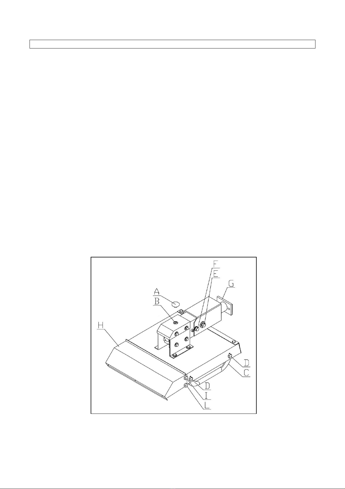
INSTRUCTIONS FOR USE
BEFORE BEGINNING WORK
a) Adjust front baffle opening as follows:
1. Unscrew and take out the two screws "L" and unscrew the two screws “I” on two machine sides.
2. Adjust position of baffle "H".
3. Plug in and lock screws "L", lock the screws “I”.
b) Adjust cutting height operating as follows :
1. Unscrew and take out the screws "D" on machine right side.
2. Adjust cutting height moving slide "C" towards up to decrease and towards down to increase.
3. Plug in and lock screws "D".
4. Repeat the same operations on the other machine side make sure to set up the same cutting
height on the two slides.
c) Hook the machine to the walking tractor operating as follows :
1. Put the machine and the walking tractor on a flat ground and loosen screws "E" and "F".
2. Lean all slides "C" flat side on the ground.
3. Approach the machine to the walking tractor, insert screws in the holes of flange “G” and lock
with washers and nuts.
4. Lock screws "E" and "F".
5. Check oil level in the gear box removing cap “A” and unscrew plug “B” (see point “2-a page 10).
7

TO BEGINNING WORK
a) Keep people and animals at least 65 feet radius all around the machine.
b) Raise the machine from ground.
c) Connect PTO power and gradually bring it to good speed.
d) Pull down slowly the machine and start the work.
AT THE END OF WORK
a) Stop the walking tractor.
b) Disconnect PTO power.
c) Raise the machine and clean its lower side.
8

MAINTENANCE INSTRUCTION
On schedule "A" the maintenances are indicated with their terms to effect on the machine.
Not follow the scheduled terms can compromise the functionality of the machine and in this case the
warranty is not applicable.
SCHEDULA "A" - SCHEDULED MAINTENANCE
FIRST
START AFTER 10
HOURS EACH 30
HOURS EACH 500
HOURS END
SEASON BEGIN.
WORK END
WORK
MACHINE Cleaning
Cleaning
GEAR BOX Level Level Change oil
HUB Greasing Greasing
SCREW Locking Locking
BLADE
Check
Sharpness
Balance
Check
Cleaning
FRONT RUBBER
PROTECTION Check
REAR RUBBER
PROTECTION Check
9

1. GREASING
The only greasing point is equipped with greaser HYDRAULIC TYPE MODEL “A” UNI 7663.
To grease use only MULTIFUNCTIONAL GREASE LITHIUM BASED Type NLGI 2.
The only greasing point is the point “C” located on one side of the hub.
Greasing operation must be made at the terms scheduled on schedule “A”.
2. OIL LEVEL - OIL SUBSTITUTION
At scheduled time on schedule "A", change oil in gear box.
Use only OIL SAE 90 EP.
Gear box capacity: 0,350 l
a) To check oil level in gear box, operate as follows :
1. Unscrew plug "B" after removing cap “A”.
2. With the machine straight and on level check oil level.
3. If necessary fill oil.
4. Screw plug "B" and put in position cap “A”.
b) To check oil level in gear box, operate as follows :
1. Unscrew plug "B" after removing cap “A”.
2. Turn upside down the machine and drain oil in a suitable tank.
3. Put the machine straight and on level, put oil through hole "B".
4. At the end of fill screw plug "B" and put in position cap “A”.
10

3. BLADE SUBSTITUTION
a) To change blade, operate as follows:
1. Unscrew nut "A" and take off pin "D" with respective spacer “B” from blade "C".
2. Plug in pin "D" in new blade putting pin head in the suitable slot, insert the spacer “B”.
3. Plug in pin in the blade case and lock nut "A”.
11

PROBLEMS SOLVING
TROUBLES GROUNDS AND SOLUTIONS
Abnormal vibrations
-Damaged blade - Replace
-Broken blade - Replace
-Not balanced blade - Balance
Uneven or unsatisfactory cut -Not sharp blade - Sharp
12

TRANSPORT
Except when working, moving the machine takes place when the machine is standing still and the
transmission is disconnected.
<Important>: keep speed low avoiding holes and ground roughness.
<Important>: Before begin the movements always make sure that the safety hooks be in position.
<Note when on the road, obey existing traffic laws. Exhibit the signal signs on the rear ends. Respect
any local laws there may be.
STORAGE
Store the machine in a dry place that isn't dusty.
INFORMATION ON DEMOLITION
At the end of its working life, the machine must be sent to be demolished and that can only be
done by an authorized authority, in accordance with the national laws in force for the environment.
Therefore it is necessary to get information from the qualified local authorities on the procedure to follow.
The machine is mainly composed of: iron materials and paints.
WARRANTY
The machine is covered by the manufacturer warranty for a period of 24 months.
The warranty is not applicable when:
a) The maintenance work has not been done correctly.
b) The machine has been used out of its own service.
c) The machine has been transformed or modified without the manufacturer's written authorization.
13

WORK AND MAINTENANCE SHEET
Every user should register on this sheet the facts about the life of the machine (both work and maintenance),
so as to attest its conditions.
DATE WORKING
HOURS MAITENANCE NOTE USER
14

YOUR OBSERVATION FOR IMPROVEMENTS
Customers can record on this sheet any observations on the performance of the machine, including possible
problems.
Observations coming directly from the work field are of great help in improving the product. We now thank
those who will give us this help.
SPARE PARTS ORDERS
If you must order some spare parts, please follow these instructions :
Take the spare parts list and the spare parts drawing enclosed in this manual.
Identify the spare parts to order with respective code and quantity and make a list of them
Find the identification table, showed below, placed on the top of the deck and write on the list the
“MODEL”, “SERIAL NUMBER” and “YEAR OF PRODUCTION” of your machine .
Send the list to your dealer.
15

SPARE PARTS
16
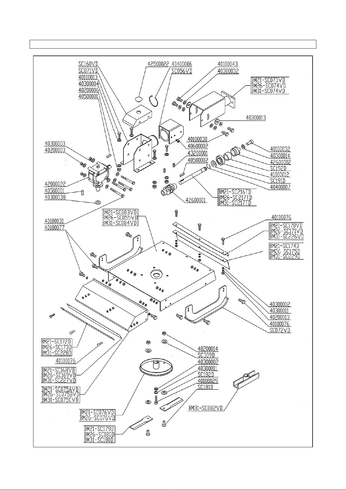
BM21 – BM26 – BM31 / 2008 BCS SPARE PARTS
17
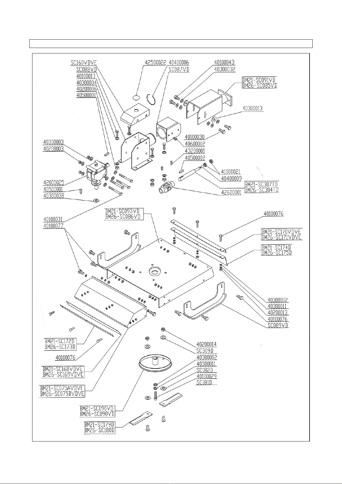
BM21 – BM26 GRILLO / 2008 GRILLO SPARE PARTS
18
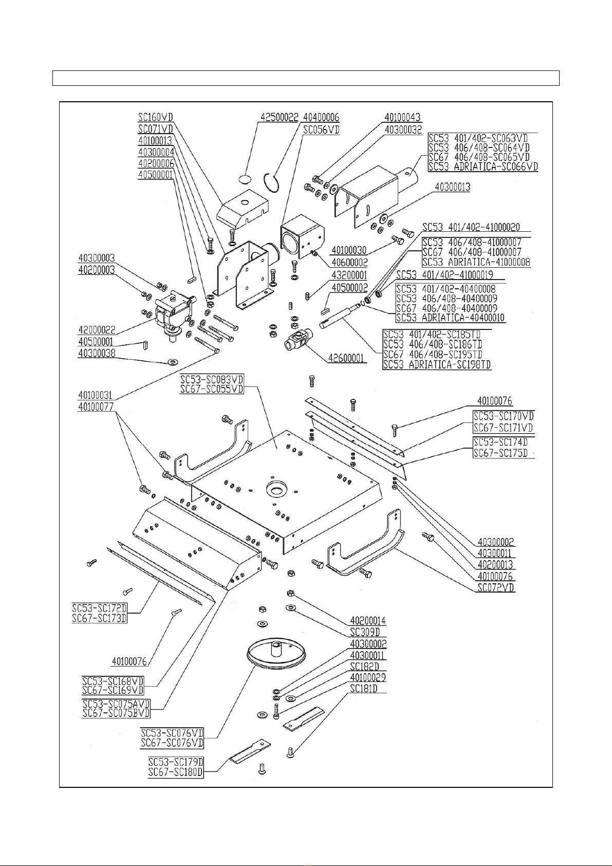
SC53 – SC67 / 2008 SPARE PARTS
19

20
TABLE OF CONTENTS
PREFACE.........................................................................................................................................................................2
DESCRIPTION.................................................................................................................................................................3
PERFORMANCES.......................................................................................................................................................3
PERFORMANCES LIMIT............................................................................................................................................3
STANDARD EQUIPMENT..........................................................................................................................................3
TECHNICAL SPECIFICATION .....................................................................................................................................4
SAFETY INFORMATION...............................................................................................................................................5
GENERAL REGULATIONS........................................................................................................................................5
SAFETY RESTRICTIONS..........................................................................................................................................5
SAFETY SIGNS ON THE MACHINE............................................................................................................................6
INSTRUCTIONS FOR USE............................................................................................................................................7
BEFORE BEGINNING WORK...................................................................................................................................7
TO BEGINNING WORK..............................................................................................................................................8
AT THE END OF WORK.............................................................................................................................................8
MAINTENANCE INSTRUCTION ..................................................................................................................................9
SCHEDULA "A" -SCHEDULED MAINTENANCE...................................................................................................9
1.GREASING.........................................................................................................................................................10
2.OIL LEVEL -OIL SUBSTITUTION.......................................................................................................................10
3.BLADE SUBSTITUTION...................................................................................................................................11
PROBLEMS SOLVING.................................................................................................................................................12
TRANSPORT .................................................................................................................................................................13
STORAGE ......................................................................................................................................................................13
INFORMATION ON DEMOLITION.............................................................................................................................13
WARRANTY...................................................................................................................................................................13
WORK AND MAINTENANCE SHEET.......................................................................................................................14
YOUR OBSERVATION FOR IMPROVEMENTS......................................................................................................15
SPARE PARTS ORDERS............................................................................................................................................15
BM21 – BM26 – BM31 / 2008 BCS SPARE PARTS ..............................................................................................17
BM21 – BM26 GRILLO / 2008 GRILLO SPARE PARTS......................................................................................18
SC53 – SC67 / 2008 SPARE PARTS........................................................................................................................19
This manual suits for next models
8
Table of contents
Other Del Morino Lawn Mower manuals


Popular Lawn Mower manuals by other brands


Matrix
Matrix AUTOMOWTIC MOW800 Operational manual

GreenWorks Pro
GreenWorks Pro CRZ426 Assembly guide

Alamo Industrial
Alamo Industrial Axtreme FC-P-0002 parts manual

Royal
Royal RPM 46/1 S-SE operating instructions

Craftsman
Craftsman 247.37032 owner's manual

Snapper
Snapper SCRAMBLER YZ18386BVE Safety instructions & operator's manual


