Del Morino OMEGA 11 User manual


Omega-e-04 Use and maintenance manual : OMEGA
Del Morino srl , v.Caroni di Sotto 19,
I-52033 Caprese Michelangelo AR Italy
Ph: +39-575-791059 Fax: +39-575-791210
E.mail: export@del-morino.it
http://www.del-morino.it
USE AND MAINTENANCE MANUAL
OMEGA
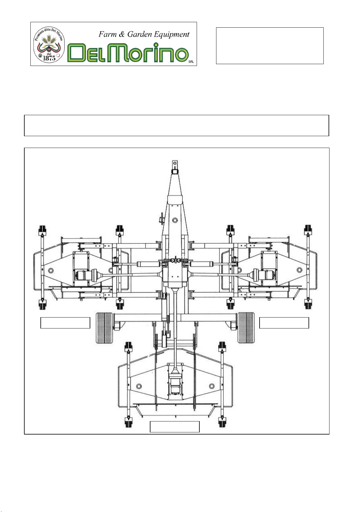
LEFT
REAR
RIGHT

2
PREFACE
This manual is an integral part of the machine.
It must always accompany the machine and be kept within reach of the operator.
The enclosures mentioned are on integral part of this manual.
The purpose of this manual.
This manual gives information for the correct and safe use of the machine.
The owner must read this manual carefully before work with the machine.
Responsibility of the owner
The owner is responsible for accidents or damages caused to people or things due to negligence in following
the instructions in this manual.
Assistance in using this manual
Explanations: contact the dealer.
Request for additional copies of the manual: in case of loss or wear and tear, or in case one wants the
manual in a different language, the customer should ask the dealer or manufacturer.
Pay attention to the warning signals
<Danger>: indicates a situation that is potentially dangerous which, if not avoided, will cause death or
serious
damage.
<Warning>: indicates a situation that is potentially dangerous which, if not avoided, will cause death or
serious damage.
<Caution>: indicates a situation that is potentially dangerous which, if not avoided, can cause minor to
moderate damage, or it indicates to be careful about an unsafe procedure.
<Important> : indicates instructions that must be followed precisely in order to avoid damage to the product,
process
or environment.
<Note>: indicates supplementary information.

3
DESCRIPTION
FUNCTION OF USE
The machine gives grass a professional cut. The grass is first raised, then cut with precision and discharged
in the rear side along the width of discharge.
It perfects any preliminary cut.
The machine is formed by 3 cutting components; each one moves in the soil with 4 pivotal wheels; each
component is free in the movements to adjust itself to the soil.
Each component takes the motion through homokinetic joints by a gear box with 4 way actioned by the PTO
of the tractor.
The 3 components follow perfectly the line of the soil making a uniform cutting action of high quality.
PERFORMANCES
The frame, where the cutting components are connected, permits to raise the 3 mowers for the transport,
through a hydraulic integrated system.
The pivotal wheels of the components, permit the best control both on forward gear and reverse gear; the
wheels have dimensions so as not to damage the turf.
The height of the cut is adjustable from 1 to 4 inches through distance washers that can be inserted in the
vertical pivotal axles.
The components always has their 4 wheels on the ground.
The small chains situated at the exit of the rear discharges, are a protection for eventual throws of objects
that could be hidden on the turf. Also, they disperse evenly the cut grass.
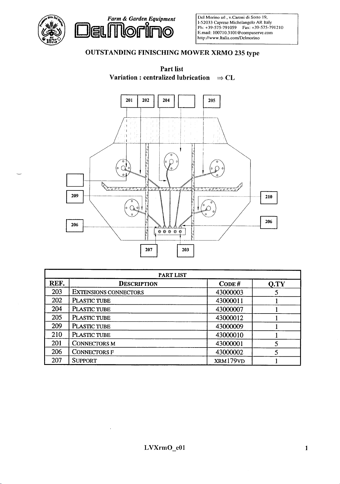
The cutting components of the machine, have the "central" lubrication of the blade-supports; in this way, the
operator can see and approach immediately the lubrication points.
PERFORMANCES LIMITS
Maximum forwarding speed : 5 m.p.h.
Speeds greater than the maximum can compromise the condition of the machine, the quality of the work
and the safety of the operator.
Maximum power applicable to the gear box: 41 Kw ±5% with 540 r.p.m.
Superior power to which is indicated can damage irreparably the transmission gear box; especially
during heavy works.
STANDARD EQUIPMENT
- Clutch cardan shaft.
- Mowers with rubber wheels.
- Centralized lubrication.
VARIANTS & OPTIONS
- Mowers with rubber wheels φ
φφ
φ310.
- Mowers with pneumatic wheels φ
φφ
φ330.
- Wide angle clutch cardan shaft.
4
SAFETY DEVICES
The machine is equipped with a lock device with a manual unhooking that keep the casual descent of the 3
cutting components during the transport and maintenance operations.
TECHNICAL SPECIFICATIONS
DRAW-HOOK OF THE TRACTOR
The diameter of the hitch pin must not be less than 30 mm., the pin must be produced in C 40 steel or similar
and must be equipped to the extremities of a hole to apply the safety spring pin.
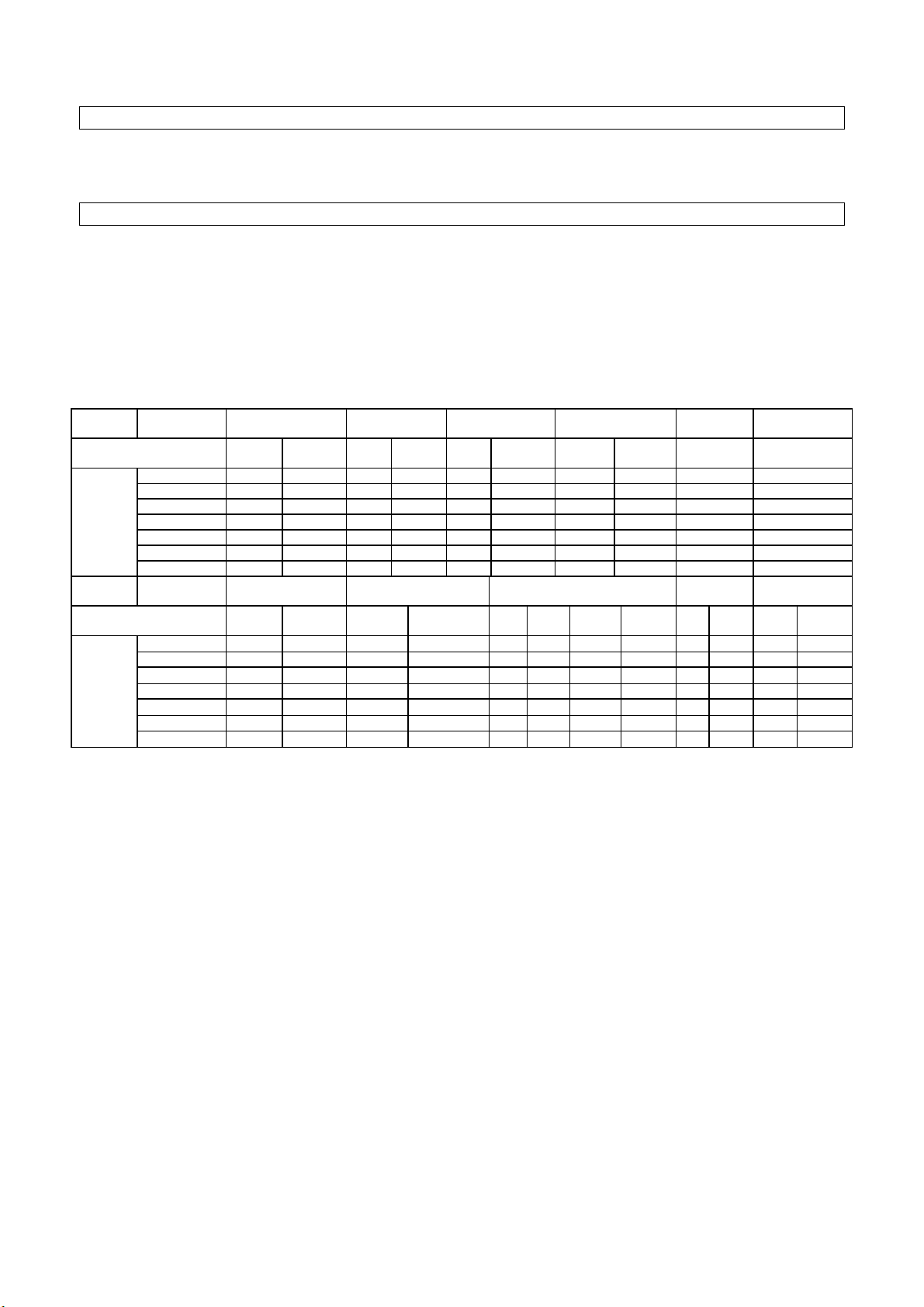
CHARACTERISTICS PER MODEL
Model
Type Mowers Cutting width Cutting height Blade tip speed Blade speed Blade number
Side Rear Ft mm Inch mm F/M m/s R.p.m. N°
11 2x48” 1x48” 132” 3300 1÷4 25÷100 13773 4225 3250 (3x3) =9
12 2x48” 1x60” 144” 3600 1÷4 25÷100 (3x3) =9
14 2x60” 1x60” 168” 4200 1÷4 25÷100 13718 4208 2630 (3x3) =9
15 2x60” 1x72” 180” 4500 1÷4 25÷100 (3x3) =9
17 2x72” 1x72” 204” 5100 1÷4 25÷100 14083 4320 2250 (3x3) =9
19 2x72” 1x93” 222” 5650 1÷4 25÷100 (3x2)+5 =11
OMEGA
21 2x85” +1x93” 2502 6350 1÷4 25÷100 16104 80 2125 (3x2)+5 =11
Model
Type Mowers Power consumption
Kw R.p.m.
Storage
Width Lenght
Work speed Weight
Side Frontal
Central Secondary Inch m Inch M km/
h
Mi/h Lbs Kg
11 2x48” 1x48”
41÷
÷÷
÷540 16 94” 2,40 141” 3,60 15 9,5 2222 1010
12 2x48” 1x60” 94” 2,40 141” 3,60 15 9,5 2244 1020
14 2x60” 1x60”
41÷
÷÷
÷540 16 94” 2,40 147” 3,75 15 9,5 2332 1060
15 2x60” 1x72” 94” 2,40 147” 3,75 15 9,5 2376 1080
17 2x72” 1x72”
41÷
÷÷
÷540 16 96” 2,45 153” 3,90 15 9,5 2508 1140
19 2x72” 1x93” 96” 2,45 153” 3,90 15 9,5 2684 1220
OMEGA
21 2x85” +1x93”
41÷
÷÷
÷540 16 98” 2,50 153” 3,90 15 9,5 2860 1300

5
SAFETY INFORMATIONS
GENERAL REGULATIONS
Only work in daylight.
The machine must not be used near people, especially children or animals.
Wear long pants and heavy shoes.
The protections are integral part of the machine: always work with the protections.
Make sure that the 4 wheels of all components be adjusted to the same cutting height.
Pay attention to the soil: make sure that are not stones, sticks, iron wires, etc…
Pay attention using the machine on slopes: proceed to the maximum slope and never work in slanting
direction.
Before leaving the driver's seat, turn off the engine and disengage the transmission engine-shaft.
Check immediately the machine if it touches foreign objects.
Check immediately the machine if there are unusual strong vibrations.
Change quickly defective parts.
SAFETY RESTRICTIONS
Children and people who are not familiar with these instructions must not be permitted to use the machine.
Local regulations can restrict the use of the machine in accordance to the age.

6
SAFETY SIGNS ON THE MACHINE
In this section, the safety signs on the machine are reproduced and explained.
1 2 3 4 5 6
1. Read the operator manual.
2. Disconnect the tractor key before maintenance and repair operations.
3. Stay at safety distance from blades when machine is moving.
1. Danger of flying objects. Stay at safety distance.
4. Stay at safety distance from blades when machine is moving.
5. Stay at safety distance from blades when machine is moving.
The safety signs on the machine must always be legible.
In case of damage, the labels of the signs must be substituted.
In the case of the substitution of machine parts that have safety signs, the signs must be replaced.
Supplying of new safety labels and the application procedure
Contact your dealer to receive new safety labels with instructions for application.

7
ASSEMBLING INSTRUCTIONS
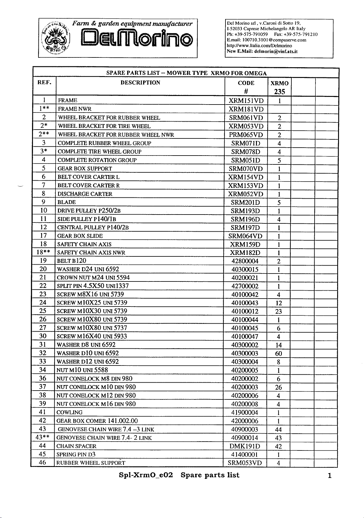
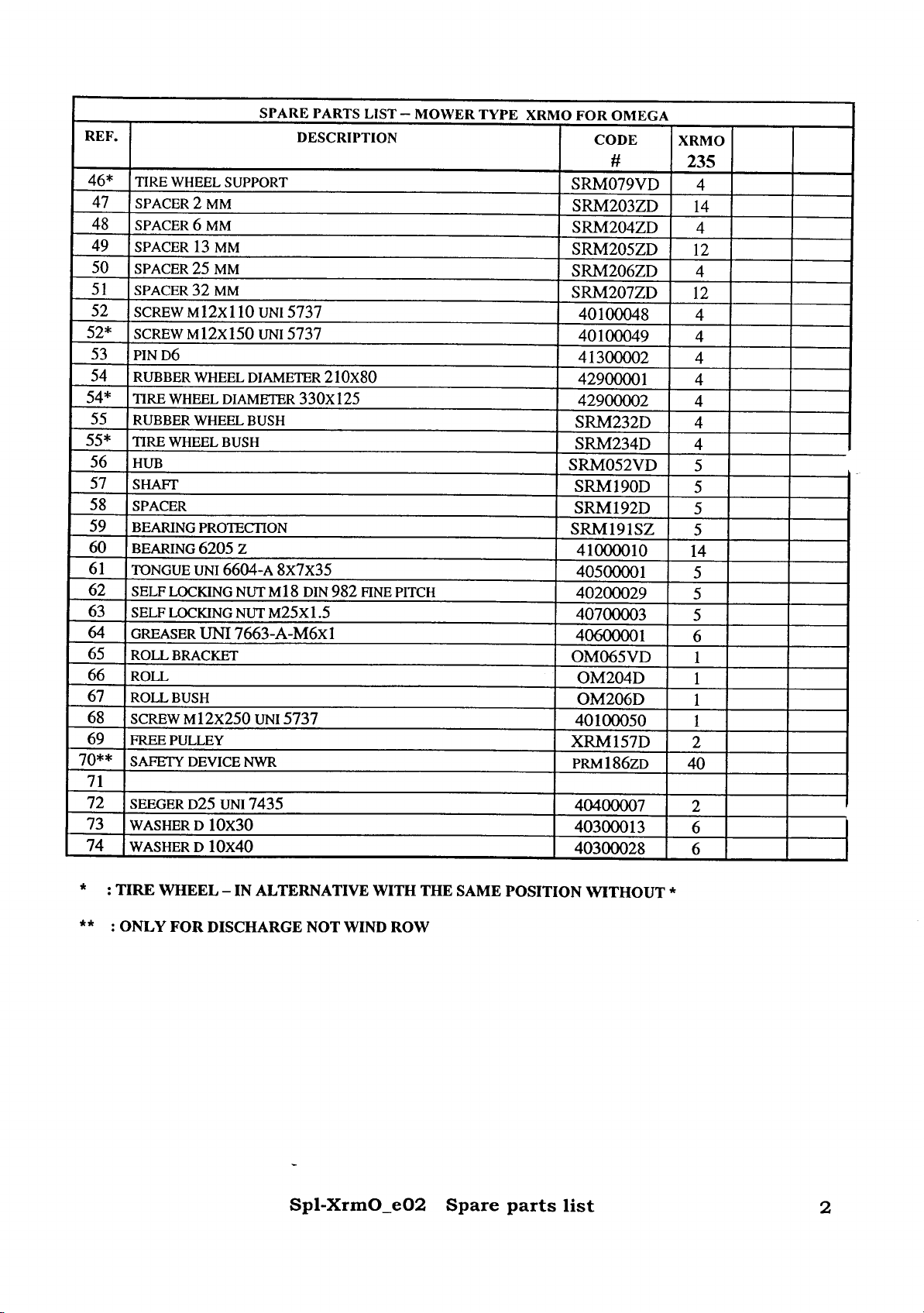
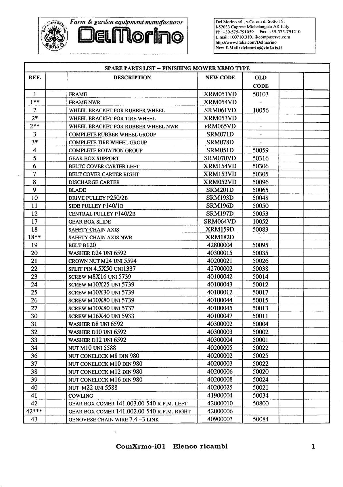
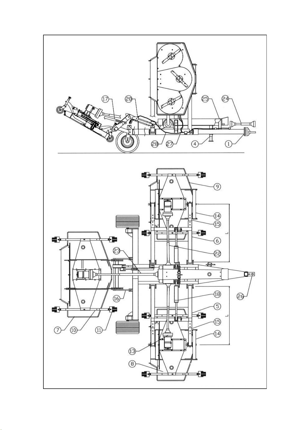
PARTS LIST
POS. DESCRIPTION Q.TY’
1 MAIN FRAME 1
2 REAR HUB 2
3 REAR WHEEL 2
4 LIFTING JACK 1
5 RIGHT SIDE CONNECTION FRAME 1
6 LEFT SIDE CONNECTION FRAME 1
7 REAR CUTTING COMPONENT 1
8 RIGHT SIDE CUTTING COMPONENT 1
9 LEFT SIDE CUTTING COMPONENT 1
10 CROSS BAR WHEEL CASE 6
11 MOWER WHEEL GROUP 12
12
13 CASING 3
14 SIDE CONNECTION BRACKET 4
15 SIDE CONNECTION BEAM 4
16 REAR CONNECTION FRAME 1
17 REAR END STROKE ROD 2
18 HYDRAULIC RAM 3
19 SIDE SAFETY DEVICE 1
20 REAR SAFETY DEVICE 1
21 SIDE END STROKE ROD 2
22 SIDE HOMOKINETIC CARDAN JOINT 2
23 REAR HOMOKINETIC CARDAN JOINT 1
24 POWER CARDAN JOINT 1
25 POWER DRIVING GROUP CARTER 1
26 DRAW-HOOK 1
27 SIDE HYDRAULIC PIPE 2
28 REAR HYDRAULIC PIPE 1
OMEGA is delivered disassembled in the parts listed in the PARTS LIST, for transport necessities.
All bolts, pins, safety clips pins, the click pins, the distance washers, are supplied already inserted in
their seats.
For a perfect assembling operation of the mower, must refer to the assembling scheme and to the
assembling instructions showed in this manual.
To avoid problems, follow scrupulously the succession of the steps indicated in the instructions utilizing
only the bolts and accessories supplied with the machine.
The assembling of the machine doesn't request any special equipment, during assembling steps, follow
the normal anti-labour accident regulations.
8

9
This manual suits for next models
6
Table of contents
Other Del Morino Lawn Mower manuals


