DELAVIN W101 User manual
MODELS:
SHOWER DOORS: W101/W101B/W101G
TUB DOORS: W707/W707B
DELAVIN®
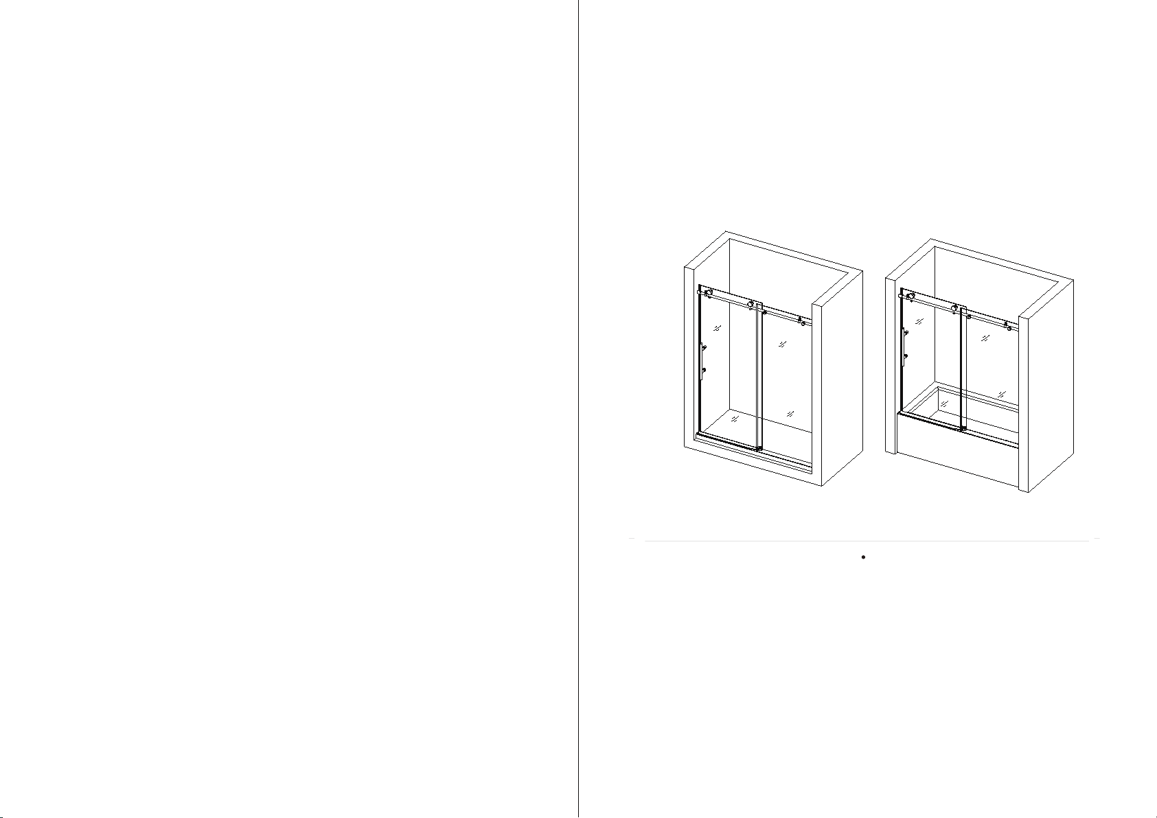
INSTALLATION INSTRUCTIONS
SHOWER DOORS TUB DOORS
R
DELAVIN
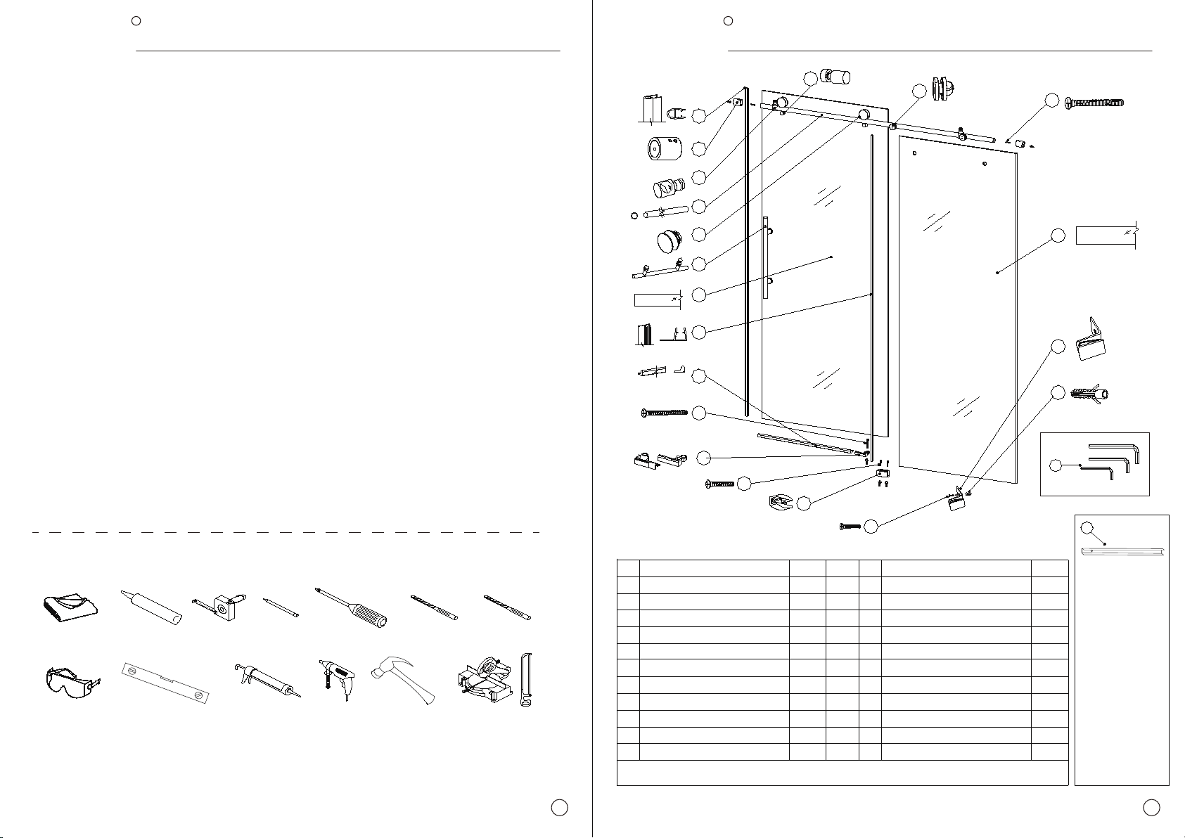
TOOLSREQUIRED
OTHER TOOLS MAY BE REQUIRED
Level Caulk Gun Drill Hammer M itter Saw
or Hacksaw
CaulkSoft Cloth
or Blanket
Safety Glass
Tape
M easure Pencil Phillips
Screwdriver
Drill Bit
(Ø=5/ 16")
Drill Bit
(Ø=3/ 8")
PREPA RA T I ON
1
1. We strongly recommend that this product be installed by a licensed and insured professional contractor, including
the assistance of a second person during installation.
2. After opening all boxes and packages, please read this introduction carefully. Check that all required parts are
included in the package by marking all components on the Shower Door Components Detail Sheet. Inspect boxes
and packages for shipping damage. If the unit has been damaged, has a finishing defect or has missing parts,
please contact our customer support department within 3 business days of the delivery date. Please note that
DELAVIN will not replace any damaged products or missing parts free of charge after 3 business days or if the
product has been installed. Feel free to contact DELAVIN if you have any questions.
Attention: Please double check the glass corners and four edges of the two glass doors to ensure that all glass is in
perfect condition and without any breakage. Do not attempt to install a shower door if the glass corners are broken.
3. Please note that if you are in doubt about installation compliance standards, please consult your local building
codes. Building and plumbing codes may vary by location and DELAVIN is not responsible for your project's code
compliance standards and does not accept any returns.
4. Before installation, make sure the installation surface is leveled and solid, and can support the total weight of the
unit. Also, make sure the walls are at right angles. Irregular mounting surface levels or improper angle of side walls
will cause serious problems during installation. Note that some adjustments and drilling may be required during
installation.
5. Protect all major surfaces of the product during installation. Never place glasses directly on tile floors. Leave the
corner protector in place until it needs to be removed. Always use a piece of wood or cardboard to protect the
bottom edges and corners of the glass before and during installation.
R
DELAVIN
2
1
2
3
4
5
6
7
8
9
10
11
Bumper Strip
Guide Rail Bracket
Glass Door Stopper
Roller
Handle
Glass Door
Anti-splash Threshold
1 pc
2 pcs
1 pc
1 pc1 set
12
13
14
2 pcs
3 pcs
2 pcs
1 pc
2 pcs
1 pc
1 pc
1 pc
2 pcs
1 pcs
1 pc
7 pcs
16
17
18
20
15
19
No. Description QTY No. Description QTY
1 pc
2
22
1
Side Anti-Water Strip
1 pc
Upper Guide Rail
A
Measuring tool
llen Key
1
2
3
4
5
6
7
8
9
14
20
19
16
17
15
13
18
21
12 23
2 pcs
Glass Door
Stationary Glass
10
2 pcs
2 pcs
11
Screw M4X25
Aluminum Cover(optional)
Screw M4X30
Screw M4.8X32
Guide Block
Wall Anchor
L Wall Cover
Stationary Glass
Screw M5X40
Glass Bracket
Safety Pin
TEAR OFF THE GLASS PROTECTIVE FILM BEFORE INSTALLATION
Measuring tool
(No installation
required):
Only used for
marking hole
positions, please
place this piece
of aluminum on
the ground
against the wall,
and mark on the
wall according to
the holes in the
aluminum,then
you can make
the hole.

R
DELAVIN
3
R
DELAVIN
d. e. f.
g. 3
3
2
234
19
a. b.
Bracket core
Front
c.
Bracket core screw
2
2
419
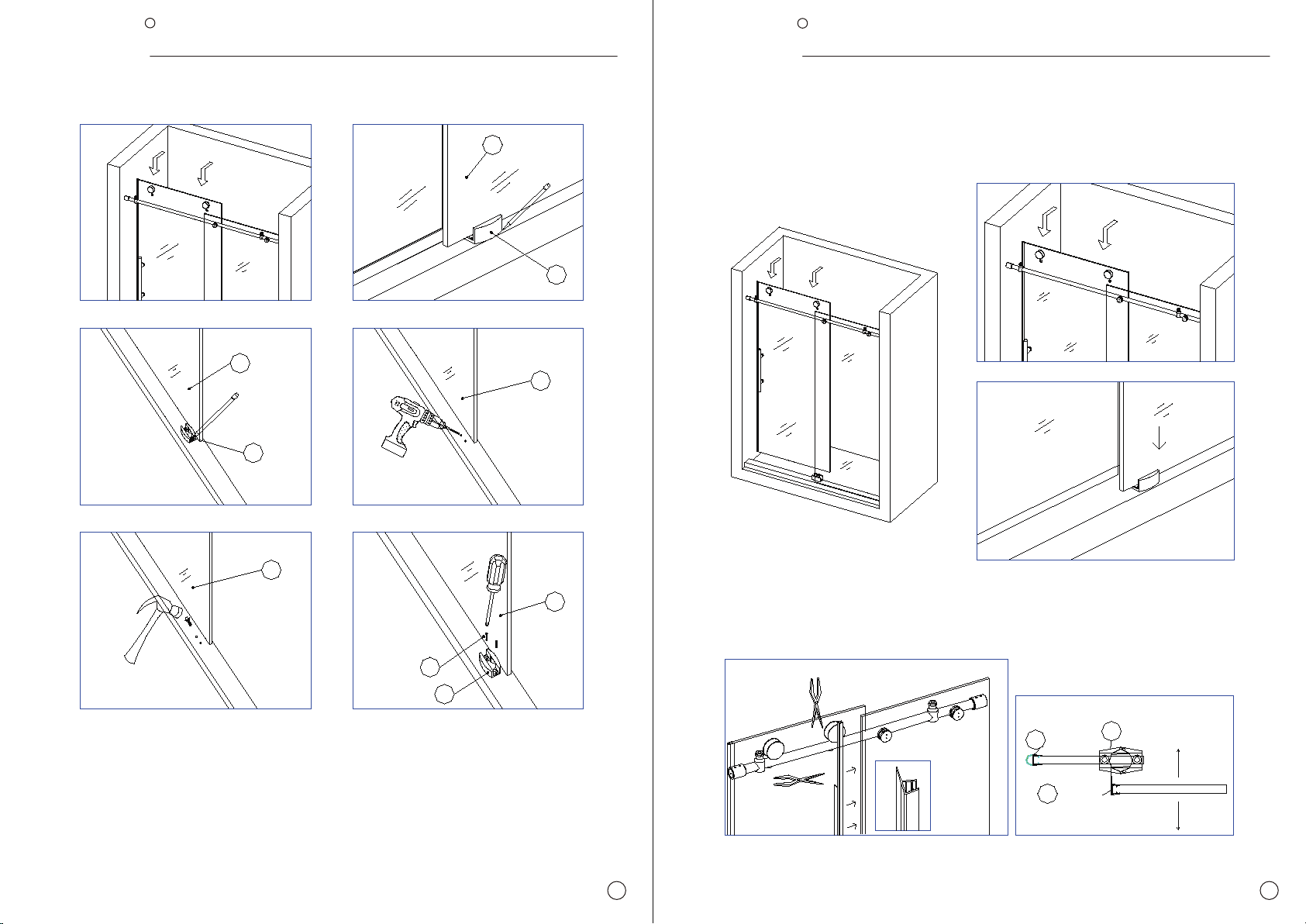
1.Determine a suitable location and place the stainless steel spacers on the support rods as shown.
Use the Allen key (21) to loosen the screws on the rail bracket (2) and the glass door stop (3).
First put (3) on the stainless steel support rod and fix it in the approximate position as shown in the figure,
Then place (2) on both ends of the stainless steel support rod. Then disassemble (19) as shown in the
figure, and fix half of it at the small hole of the stainless steel support rod.
2
3
4
a.
b.
17
Wood
ATTENTION:
2.Place the Stationary Glass (17), align the
hole above the glass with the Glass
Bracket (19) that has been fixed with the
stainless steel support rod, Cover the other
half of the Glass Bracket (19) to lock the
glass (two spacers are placed separately to
protect the glass).
Never set your glass down directly
onto a tile or concrete floor.
Always use a piece of wood or cardboard
and leave the corner pads on the glass
until it becomes necessary to remove
them to protect the bottom edge and
the corners of the glass from breakage.
R
DELAVIN
5 6
R
DELAVIN
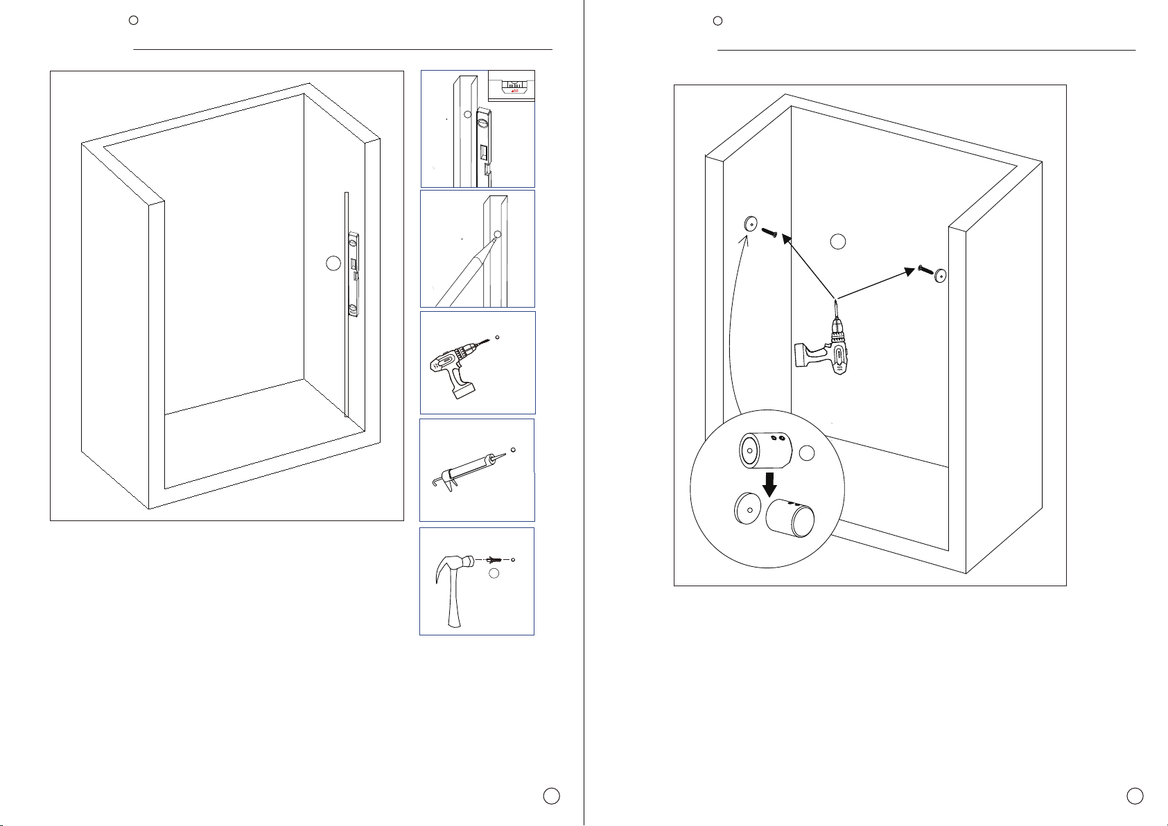
3. Place the Measuring Tool(23) vertically against the wall on the floor, mark the wall
according to the holes in the Measuring Tool(23).
Drill holes in the determined position and apply silicone into the holes, insert the
Wall anchors (15) for the Guide Rail Bracket.
Screw M5*40
a.
d.
e.
f .
b.
c.
III
23
18
15
2
Measuring
tool
Wall Anchor
4.Divide the Guide Rail Bracket(2) into two parts: I and II
Fix part I of the Guide Rail Bracket(2) to the wall on both sides with 5*40 screws
(18) as shown in the picture g.
The other side of the Guide Rail Bracket (2) is installed in the same way.Finally,
remove the II part of the Guide Rail Brackets (2) and insert it into the Upper Guide
Rail (4).
R
DELAVIN R
DELAVIN
e. g.
16
f.
4.8*32
22
a. b.
c. d.
5
21
5
7
7
6
d.
1
55
7
6
b.
a.
c.
e.
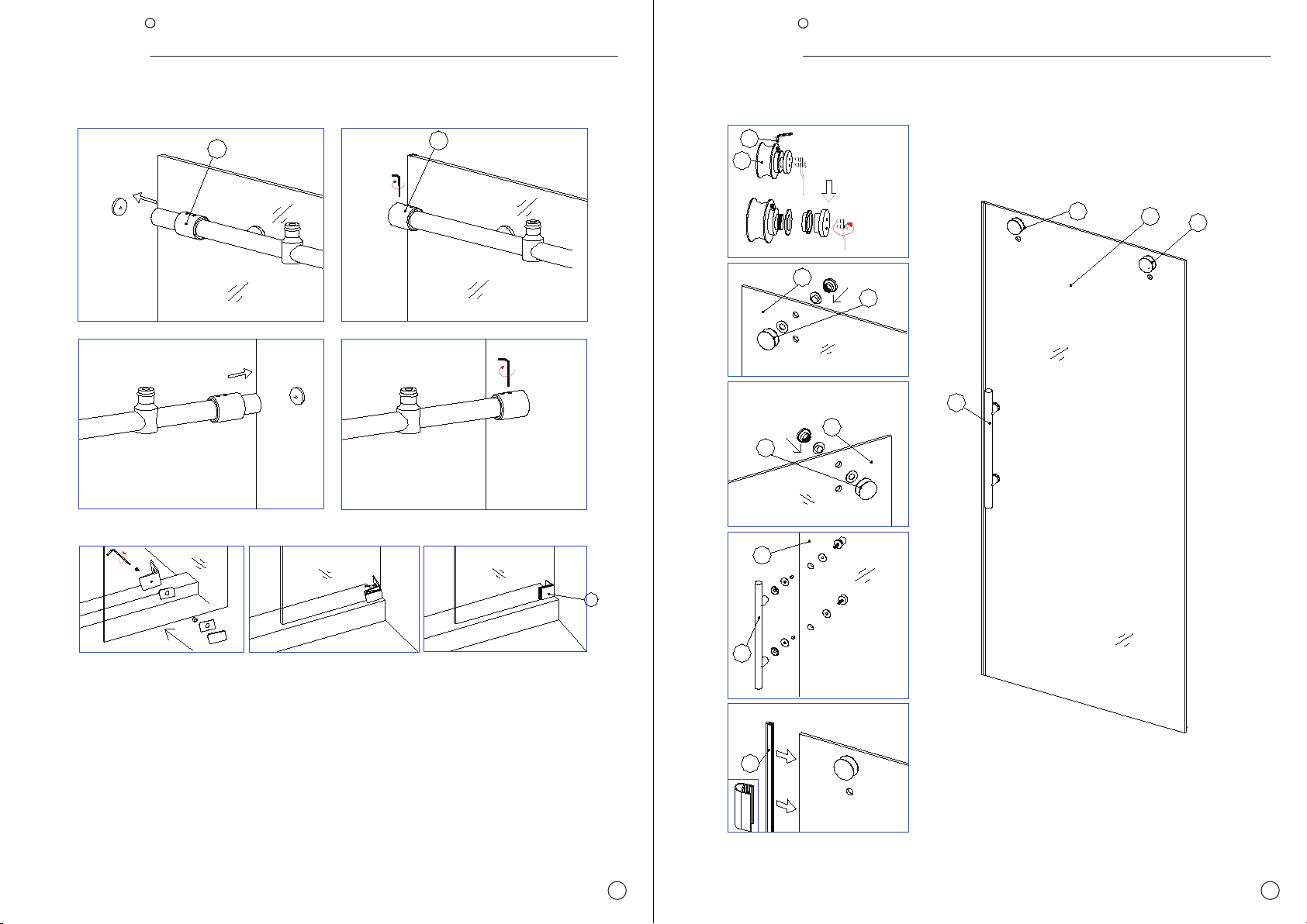
Attention: Need to loosen the small allen screws before
loosening the long allen screw on the roller
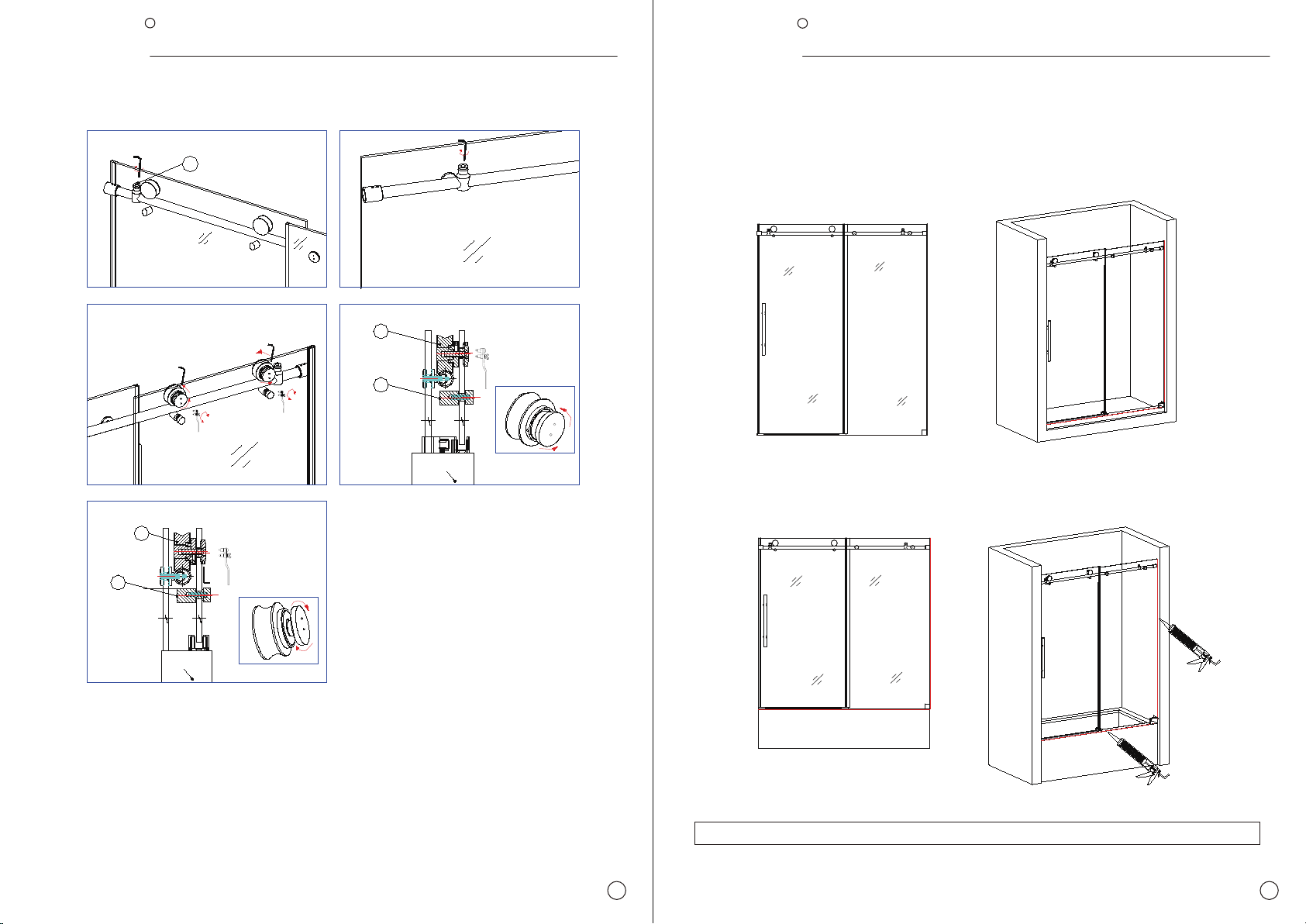
6. Loosen the Rollers (5) screw as shown in the figure to
disassemble the rollers (5) and install the rollers to the glass
door (7). And then Install Handle (6) and Bumper Strip (1) to
the glass door (7).
7 8
5
7
5. Place the Stationary glass (17) back into the designated position. Slide the II part
of the Guide Rail Brackets (2) to the two end sides of the Upper Guide Rail (4),
then connect II and I part of the Guide Rail Brackets (2). Tighten the set screws on
the Guide rail bracket (2) with Allen Key (21) to secure the guide rail to the wall.
Cover the L wall cover (16) with glass on one side, and lock the L wall cover on the
wall with Screw M4.8X32 (22) on the other side.
R
DELAVIN R
DELAVIN
7.Hang the Glass Door (7) installed with rollers, handles and strip to the Upper Guide Rail (4). Slide the
Guide Block (14) to the bottom of the glass door. Mark down the predrilled position of the guide block.
Set the glass door aside. Now drill the hole with drill bit to the threshold. Put the silicone to the hole and
then put the wall anchor (15) into the hole. Now secure the guide block to the threshold with Screw
M4X30 (13).
17
14
17
17
17
13
14
14
7
a.
c.
e.
b.
d.
f.
Screw M4X30
9
a.
b.
a.
b.
114
8
Moving glass
Statinary glass
Waterproof strip
Sealing strip
Bottom guide block
Outerside
Inner side
8. Hang the Glass Door (7) back to the Upper Guide Rail (4) , slide the bottom of the glass door into
the slot of the Guide Block (14) . Be careful that the glass door should not touch the metal part of the
guide block.
9. Slide the Side Anti-Water Strip (8) to the Stationary Glass (17) , remove the flapper that nterferes
with the Upper Guide Rail (4)
10

R
DELAVIN R
DELAVIN
11
10.Install the Anti-Splash Threshold (9) in front of
the Glass Door (7). Put the Anti-splash threshold
in front of the glass door, and then put the
Aluminum Cover with slot into the Stationary
Glass(17), on top of the threshold.
Put the other cover to the other side. Mark down
the predrilled holes on the threshold, drill the
holes with drill bit, put the wall anchor (15). Put
slicone sealant to the bottom of the Anti-splash
threshold, secure it to the threshold with M4x25
Screw (10) and put the covers back on it.
10
Screw M4X25
a. b.
d.
c.
e.
e.
g.
911
15
b.
Fixed base
Clear Gasket
Washer
Clear Gasket
Inner cover
20 a.
c.
Fixed base
Gasket
Washer
Gasket
Inner cover
Fixed base
Gasket
Washer
Gasket
Inner cover
11. Install the Safety Pin(20) to the Glass
Door (7). Make sure that the clear gasket
will be between the glass and the metal
parts of the safety pin.
12
R
DELAVIN R
DELAVIN
c.
Moving glass outer side
3
Glass Door UP
2
11
shower t ray or
shower base
2
11
shower tray or
shower base
Glass Door down
a. b.
d.
e.
12.Adjust the Roller(5) and fix the Glass Door Stopper(3)
Adjust the fasteners on both Rollers (5) to ensure that the bottom edge of the Glass door (7) will not
touch the bottom of the guide block (14).
Slide the Door Stopper (3) close to the wall side, slide the Glass Door(7) to make roller(4) contact to
the stopper and get perfect space then lock the stopper bottom screw.
Please make sure that the Glass Door(7) especially the door corners will not hit the walls when
closed and opened
Moving glass inter side
13
TUB DOORS INSTALLATION the same as SHOW ER DOORS
MUST ALLOW SILICONE TO DRY FOR 24 HOURS BEFORE STARTING USING THE SHOWER
13. Apply silicone sealant on the seams between the stationary glass and the shower base/bathtub,
and between the wall and the stationary glass.
14
This manual suits for next models
4
Table of contents


