Delcam iQube 2010 User manual

Delcam iQube 2010
Reference Manual

Copyright © 2009 - 2010 Delcam plc. All rights reserved
Delcam plc has no control over the use made of the software described in
this manual and cannot accept responsibility for any loss or damage
howsoever caused as a result of using the software. Users are advised that
all the results from the software should be checked by a competent
person, in accordance with good quality control procedures.
The functionality and user interface in this manual is subject to change
without notice in future revisions of software.
The software described in this manual is furnished under licence
agreement and may be used or copied solely in accordance with the terms
of such licence.
Delcam plc grants permission for licensed users to print copies of this
manual or portions of this manual for personal use only. Schools, colleges
and universities that are licensed to use the software may make copies of
this manual or portions of this manual for students currently registered for
classes where the software is used.
Acknowledgements
This documentation references a number of registered trademarks and
these are the property of their respective owners. For example, Microsoft
and Windows are either registered trademarks or trademarks of Microsoft
Corporation in the United States.
Scanner Name
The name of the scanner is the Delcam iQube. Any reference to iQube in
this documentation refers to the Delcam iQube scanner and no other
product of a similar name.
Delcam iQube Version 2010. Published on 16 June 2010

Delcam iQube 2010 Reference Manual Contents • i
Contents
Introduction 1
Compliance and Safety 2
Compliance....................................................................................................2
FCC........................................................................................................2
WEEE ....................................................................................................3
Technical Specifications................................................................................5
Electrical Specifications ........................................................................5
Permissible Environmental Conditions.................................................5
Temperature Range................................................................................5
Safety Precautions..........................................................................................6
Understanding Warning Terms .............................................................6
Understanding Precaution Terms ..........................................................7
Warnings................................................................................................8
Cautions .................................................................................................9
Hardware installation and maintenance 10
Parts List ......................................................................................................11
Hardware Diagrams.....................................................................................12
Hardware diagram - legend .................................................................13
Setting up the scanner..................................................................................15
Remove the Cover ...............................................................................15
Electrical Connection...........................................................................16
Network Connection............................................................................18
Power-up the Scanner..........................................................................19
Connecting to the Scanner...................................................................21
Maintenance and Handling..........................................................................27
Maintenance.........................................................................................27
Handling...............................................................................................27

ii • Contents Delcam iQube 2010 Reference Manual
Software Installation 29
System Requirements ..................................................................................29
Installation....................................................................................................30
Test...............................................................................................................31
Using the Delcam Orthotic Insoles Software 32
Jobs Page......................................................................................................33
Adding a Job........................................................................................33
Deleting a Job ......................................................................................34
Scan Page.....................................................................................................35
Scan Model..........................................................................................38
Changing the scan settings (per session).............................................39
Changing the Default Scan Settings....................................................41
Scan mode............................................................................................46
Export Page..................................................................................................49
Scanning Procedures 51
Scanning a Foot............................................................................................52
Scanner Setup (Foot) ...........................................................................52
Orientation and Location (Foot)..........................................................54
Scan Settings (Foot).............................................................................55
Scanning a Foam Box Impression...............................................................56
Scanner Setup (Foam Box Impression)...............................................57
Orientation and Location (Foam Box Impression)..............................59
Scan Settings (Foam Box Impression)................................................60
Scanning a Cast............................................................................................61
Scanner Setup (Cast)............................................................................61
Orientation and Location (Cast)..........................................................62
Scan Settings (Cast).............................................................................63
Manufacturer Details 64
Index 65

Delcam iQube 2010 Reference Manual Introduction • 1
The Delcam iQube is a simple but powerful 3D scanner specifically
created for use in designing custom orthotic insoles. It is a versatile tool
that produces high quality orthotics and insoles.
The iQube gives complete flexibility with respect to the scan model.
Scanning a foot, a cast or a foam box impression, produces a high quality
3D image in approximately 3 seconds, saving time and improving the
quality of the output.
Using technology developed for the Aerospace industry, the iQube
scanner obtains a high level of detail using laser and multi-camera
configuration to produce a highly accurate full colour 3D image. The high
level of accuracy means that the custom orthotic is created correctly every
time, minimising the inconvenience to clients.
The Delcam iQube allows the foot to be scanned in several positions,
according to the needs of the patient.The scanner can be set up for use in
full weight bearing (Weight On), semi-weight bearing and non-weight
bearing (Weight Off) positions,
The scanner is lightweight and compact, making it fully portable; the
optional carrying case allows you to transport it for use it at different
locations. Once you have scanned the item, Delcam OrthoModel software
lets you design and manufacture the custom insole. Alternatively, use the
scan data with your existing orthotic CADCAM software.
Introduction

2 • Compliance and Safety Delcam iQube 2010 Reference Manual
Full details of Compliance, Technical Specifications and Safety
Precautions can be found in the following sections:
Compliance (see page 2).
Technical Specifications (see page 4).
Safety Precautions (see page 5).
Compliance
Refer to the following sections for compliance details:
FCC (see page 2)
WEEE (see page 3)
FCC
This equipment has been tested and found to comply with the limits for a
Class A digital device, pursuant to part 15 of the FCC Rules. These limits
are designed to provide reasonable protection against harmful
interference when the equipment is operated in a commercial
environment. This equipment generates, uses, and can radiate radio
frequency energy and, if not installed and used in accordance with the
instruction manual, may cause harmful interference to radio
communications. Operation of this equipment in a residential area is
likely to cause harmful interference in which case the user will be
required to correct the interference at his own expense.
Compliance and
Safety

Delcam iQube 2010 Reference Manual Compliance and Safety • 3
Also please note the following statement that is on a sticker adhered to
the base of the scanner body:
This device complies with part 15 of the FCC Rules. Operation is subject
to the following two conditions: (1) This device may not cause harmful
interference, and (2) this device must accept any interference received,
including interference that may cause undesired operation.
WEEE
WEEE stands for Waste Electrical and Electronic Equipment and
refers to a European Union (EU) directive regulating the disposal of
electrical or electronic equipment, including all components, sub-
assemblies and consumables, which are part of the products at the time of
discarding.
European Directive 2002/96/EC on Waste Electrical and Electronic
Equipment (the WEEE Directive) stipulates that WEEE is now subject
to regulations designed to prevent the disposal of such waste and to
encourage design and treatment measures to minimize the amount of
waste that is placed into the waste system.
The purpose of this legislation is to preserve, protect and improve the
quality of the environment, protect human health, and stimulate the
practical use of natural resources. Specifically, the WEEE Directive
requires that producers of electrical and electronic equipment be
responsible for the collection, reuse, recycling and treatment of WEEE
which the producer places on the EU market after August 13, 2005.
As an importer of electrical and electronic equipment (EEE), we have
endeavoured to meet these environmental responsibilities for managing
WEEE. The following information is to educate our customers about the
WEEE collection process.
In order to avoid any potential dissemination of hazardous substances into
the environment, the product has been labelled with the WEEE symbol
(see below) in order to alert the end-user that it should be disposed of
within the proper waste management system. That system will recycle,
reuse, and dispose of materials from this product in an environmentally
sound way.

4 • Compliance and Safety Delcam iQube 2010 Reference Manual
The symbol found on the Delcam product label, indicates that the product
meets the European Directive 2002/96/EC on Waste and Electronic
Equipment. This symbol, only applicable in European Union countries,
indicates that when this product reaches the end of its life it should not be
disposed of with normal household or municipal waste, but in an
established waste stream for WEEE.
Each EU Member State country has established a system for the
collection, disposal, and recycling of WEEE. End-users in the EU should
contact their local waste administration system for collection instructions
concerning this product.

Delcam iQube 2010 Reference Manual Compliance and Safety • 5
Technical Specifications
Refer to the following sections for details of the Technical Specifications:
Electrical Specifications (see page 5)
Permissible Environmental Conditions (see page 5)
Temperature Range (see page 5)
Electrical Specifications
Voltage AC 100 V – 240 V / 120 W
Main supply voltage fluctuations up to +/- 10% of the nominal
Permissible Environmental Conditions
For Indoor Use Only
Maximum relative humidity 80% for temperatures up to 31 deg C
decreasing linearly to 50% relative humidity at 40 deg C
Vibration (55 to 2000Hz): <= 100ms/s*s EN 60 068-2-6
Shock (6ms): <= 1000ms/s*s
Altitude: Up to 2000m
Temperature Range
Storage Temperature: 5 deg C to 40 deg C
Ambient Temperature required for measuring operation: 20 deg C
+/- 10 deg C

6 • Compliance and Safety Delcam iQube 2010 Reference Manual
Safety Precautions
This equipment has been designed and tested to ensure reasonable
personal protection and protection of the surrounding area against
damage. It has been supplied in safe condition. The user must observe the
precautions described in the following sections to ensure safe operation
and to keep the equipment in safe condition.
If this equipment is used in a manner not specified by the manufacturer,
the protection provided by this equipment may be impaired.
Different safety precautions are described in the following sections:
Understanding Warning Terms (see page 6)
Understanding Precaution Terms (see page 6)
Warnings (see page 7)
Cautions (see page 9)
Understanding Warning Terms
The table below shows the level of injuries or damages that may occur
when the equipment is used incorrectly, without paying attention to
descriptions of warnings or cautions.
Notation Description
DANGER
Indicates a hazardous situation, which can result
in death or serious injury.
WARNING
Indicates a potentially hazardous situation,
which can result in death or serious injury.
CAUTION
Indicates a potentially hazardous situation,
which can result in minor or moderate injury or
damage to the equipment.
Delcam iQube 2010 Reference Manual Compliance and Safety • 7
Understanding Precaution Terms
Precautions that must be adhered to are shown below:
Notation Description
Pay attention.
Do not undertake this action.
You must undertake this action..
Laser Safety Notice.
8 • Compliance and Safety Delcam iQube 2010 Reference Manual
Warnings
The following warnings are potentially hazardous situations that can
result in death or serious injury.
Do not damage the power cable or plug. Using a damaged
power cable or power plug may cause an electric shock, short-
circuit, smoke or fire.
Do not damage, modify, forcefully bend, twist, stretch, or
bind the power cable and power plug.
Do not put heat source close to the power cable or plug.
Do not place a heavy object on the power cable or plug.
Clean dust off the power plug periodically. Any dust on
the plug may cause insulation failure as the result of absorbed
moisture. It may also result in smoke or a fire.
Disconnect the power plug and wipe it with a dry cloth.
Operate the unit at the specified voltage.
This equipment must be operated within the AC supply voltage
range marked on the rear panel of the equipment and / or a tag
attached to the power cable. The frequency of the power supply
must be 50 or 60 Hz.
Operating at a voltage or frequency, other than the one specified
may result in smoke or a fire.
Nominal
Range
AC 100 V – 240 V
90 V – 260 V
Do not insert or pull out the power cable with a wet
hand
. Attempting this may cause an electric shock.
Do not use the instrument in an explosive
environment. Never use the equipment in rooms containing
flammable or volatile gas or vapour. Failure to observe this
warning may cause an explosion or a fire.
Do not disassemble the equipment. Attempting this may
cause an electric shock or malfunction of the equipment.
Removal of panels will expose live parts. If any adjustment,
maintenance or repair is required, it must be carried out by
qualified service personnel who are aware of the hazard involved.

Delcam iQube 2010 Reference Manual Compliance and Safety • 9
Laser light can damage your eyes. Do not stare directly
into the beam or look at it with optical instruments.
Maximum weight limit is 200kg. Do not exceed maximum
weight limit on the glass.
Do not jump on the glass.
Cautions
The following cautions highlight the potentially hazardous situations,
which could result in minor or moderate injury or damage to the
equipment.
Use the specified fuse. Verify that the correct
fuse is installed before connecting the power. Failure
to do so could result in smoke or a fire.
Do not use unauthorised fuses.
Nominal
Fuse rating
AC 100 V – 240 V
3.14A 250V (T)
Do not use the equipment if it appears to be
broken. Using potentially faulty equipment could
result in an electric shock, smoke or a fire.
Immediately turn off the equipment and disconnect
the power cable. Then contact the dealer or
representative from whom you purchased the
equipment..
This equipment uses a Class II laser.
Class II laser products do not normally cause eye
injuries, but care must be taken as it can still be quite
hazardous due to glare and temporary flash blindness.
The human blink reflex occurs within 0.25 seconds of
exposure to the Class II laser beam, providing
adequate protection. You should not try to resist
the natural blink response by staring into the
Class II laser. This could result in damage to the
eye.

10 • Hardware installation and maintenance Delcam iQube 2010 Reference Manual
Details of the hardware, setup and maintenance are included in the
following sections:
Parts List (see page 10)
Hardware Diagrams (see page 12)
Setting up the scanner (see page 14)
Maintenance and Handling (see page 26)
Hardware installation
and maintenance

Delcam iQube 2010 Reference Manual Hardware installation and maintenance • 11
Parts List
The following items are supplied:
Scanner
1 x Delcam iQube 3D Scanner.
1 x scanner cover.
1 x AC power cable (regional).
1 x network cable.
Software
1 x Custom Orthotic Insoles installation CD.
1 x software dongle.
Documentation
1 x User Manual.
Foam Box Scan Aids.
45mm Foam Box Lifters (x4).
40mm Lifter Extensions (x2).
Maintenance Kit
Glass cleaner sachets.

12 • Hardware installation and maintenance Delcam iQube 2010 Reference Manual
Hardware Diagrams

Delcam iQube 2010 Reference Manual Hardware installation and maintenance • 13
Hardware diagram - legend
The following items are shown on the hardware diagrams:
Main Unit
1.
Scanner body.
2.
Tempered glass screen.
3.
Scan activation switch.
4.
Electrical panel.
5.
AC power cable connection.
6.
Power switch.
7.
LAN cable connection
8.
USB 1 connection (DO NOT USE).
9.
USB 2 connection (DO NOT USE).
10.
Screen Release socket.
11.
End lifting handles.
12.
Side handle.
Lid
13. Lid.
14.
Lid clips (x4).
15.
Standing surface.
16.
Support legs.

14 • Hardware installation and maintenance Delcam iQube 2010 Reference Manual
Auxiliary Items
17.
AC power cable (Regional).
18.
Network cable.
19.
Custom Orthotic Insoles installation CD.
20.
Software dongle.
21.
45mm Foam Box Lifters (x4).
22.
40mm Lifter Extensions (x2).
23.
Glass cleaner sachets.

Delcam iQube 2010 Reference Manual Hardware installation and maintenance • 15
Setting up the scanner
The following sections give details on setting up for a scan:
Remove the Cover (see page 15)
Electrical Connection (see page 15)
Network Connection (see page 17)
Power-up the Scanner (see page 18)
Connecting to the Scanner (see page 20)
Remove the Cover
1. Place the scanner onto a flat surface.
2. Unfasten the clips (14) from the scanner body (1) to release the lid
(13).
3. Extend the support legs (16) and place adjacent to the scanner body
(1).
16 • Hardware installation and maintenance Delcam iQube 2010 Reference Manual
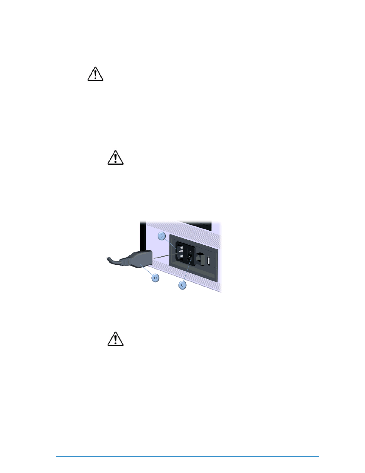
Electrical Connection
CAUTION
Always use the AC power cable (hereafter referred to as "the power
cable") that is supplied with the scanner, and connect it to an AC outlet
(100-240 V, 50/60 Hz). Failure to do so may damage the scanner,
generating an electric shock or causing a fire.
1. Set the power switch (6) on the end panel to OFF (“0”)
CAUTION
If the power cable is connected to an AC outlet when the power
switch is set to ON (“1”), damage may be caused to the scanner or
computer. Before connecting the power cable, always make sure
that the power switch is set to OFF.
2. Connect the power cable (17) to the power connector (5) located on
the electrical panel (4).
3. Plug the other end of the power cable into an AC outlet.
CAUTION
Be sure to connect the the power cable to an AC outlet that has a
earthed terminal.
Make sure that the AC outlet is located near the scanner and that
plug can be easily connected and disconnected.
Table of contents


