Delorean DMC-12 1981 Technical document
TECHNICAL
INFORMATION
MANUAL
P.J.GRADYINC(516)589-6224(800)350-7429FAX
(516)589-6241
P.J.GRADYINC(516)589-6224(800)350-7429FAX(516)589-6241
r
f&tf
DELOREANMOTORCOMPANY
r
TECHNICALINFORMATIONMANUAL
1981DeLorean
|.-^n
r
TechnicianName.
Dealership
Name.
InstructorName_
Date
PRINTED3-81

r
•*?m*$
0$l
FOREWORD
0&\
r
r
r
L
This
servicepublicationhasbeenpreparedbytheServiceTrainingDepartmentof
DeLoreanMotorCompanytoassistinunderstandingthedesignconceptsandthe
generaloperationoftheDeLorean.Itisintendedprimarilyfortheexperiencedand
qualifiedautomotivetechnicianswhohavebeenselectedtoservicetheDeLorean.
Thispublicationincludesthegeneraldescriptionandoperationofvehiclesystems
usedonthisvehiclewhichtheselectedtechniciansarebasicallyfamiliarwithaswell
asthemorespecificallydetaileddescriptionsandoperationforthesystemswhich
maybeuniquetothisvehicleand/ortheservicetechnician.
Allinformation,specificationsandillustrationsinthispublicationarebasedonthe
latestproductinformationavailableatthetimeofprinting.DeLoreanMotorCompany
reservestherighttomakechangesorrevisionsatanytimewithoutnotice.However,it
istheobjectiveofDMCandtheServiceTrainingDepartmenttoprovidetheDMCserv-
icetechnicianwithasmuchaccurateandusableserviceinformationasisavailable,
asquicklyaspossible,inordertosustaina highqualityservicestandard.
IMPORTANT:
TheDeLoreancontainsmanypartsdimensionedinthemetricsystem.Duringany
serviceprocedure,replacementfastenersmust
have
thesamemeasurementsand
strengtnasthosefastenersremoved,eithermetricorcustomary.Thenumbersonthe
headsofmetricboltsandonthesurfacesofmetricnutsindicatetheirstrength.Cus-
tomaryboltsuseradiallinesontheirheadsforstrengthindicatorswhilemostcustom-
arynutsdonothavestrengthindicators.Mismatchedorincorrectfastenerscanresult
invehicledamageormalfunction,orpossiblypersonalinjury.Fastenersremoved
fromthevehicleshouldbereusedinthesamelocationswheneverpossibleexcept
whenindicatedotherwise.Whenfastenersarenotsatisfactoryforreuse,careshould
betakentoselecta replacementfastenerthatisequivalenttotheoriginalquality.
Copyright© 1981DeLoreanMotorCompany
AllRightsReserved

TABLEOFCONTENTS
L
r
f:"^?
>ffP*i
I.
GENERALINFORMATION1
A.Engine3
B.Transmission- Manual5
C.Clutch7
D.Transmission- Automatic8
E.FrontSuspension9
F.RearSuspension
10
G.
Steering
11
H.Brakes
12
I.
HeatingandAirConditioningSystem13
J.
BodyandChassis17
II.
ENGINEELECTRICAL19
A.ElectronicIgnitionSystem21
B.StarterMotorCircuit29
C.ChargingSystem32
D.CoolingFanCircuit35
III.
FUELINJECTION39
IV.EMISSIONCONTROLS63
A.LambdaControlSystem65
B.
Idle
SpeedControlSystem77
C.EvaporativeEmissionControlSystem84
D.Air
Inlet
System87
E.IgnitionVacuumAdvanceControl88
F.DecelerationControl89
V.CHASSISELECTRICAL91
A.FusesandFuseBox93
B.RelayCompartment94
C.IgnitionSwitchCircuits96
D.WindshieldWiperSystem99
E.ExteriorLightingCircuit103
F.DoorOperated InteriorLampCircuits
.111

TABLEOFCONTENTS
(con't)
VI.
ENGINEADJUSTMENTS,TESTSANDDIAGNOSIS
A.Adjustments
1.
IgnitionTiming
117
2.
Idle
Speed118
3.COEmission119
B.SystemOperationTests
1.
LambdaSystem122
2.
Idle
SpeedControlSystem
124
C.DiagnosticCharts
1.
IgnitionSystem- "EngineWillNotStart"126
2.
FuelSystem- "EngineWillNotStart"128
3.LambdaSystem130
4.
TroubleshootingDiagnosticChart132
VII.
SPECIFICATIONS& CAPACITIES133
F
pi??.]
r
in
f

r
r
F
r
r
r
r
r
r.
r
r
r
r
r
r
r
GENERALINFORMATION
\V?TT.\
1
—•r'"\
**$&
^--^

ENGINE
PMv
fmm
r
.jpfi&f
GENERALDESCRIPTION
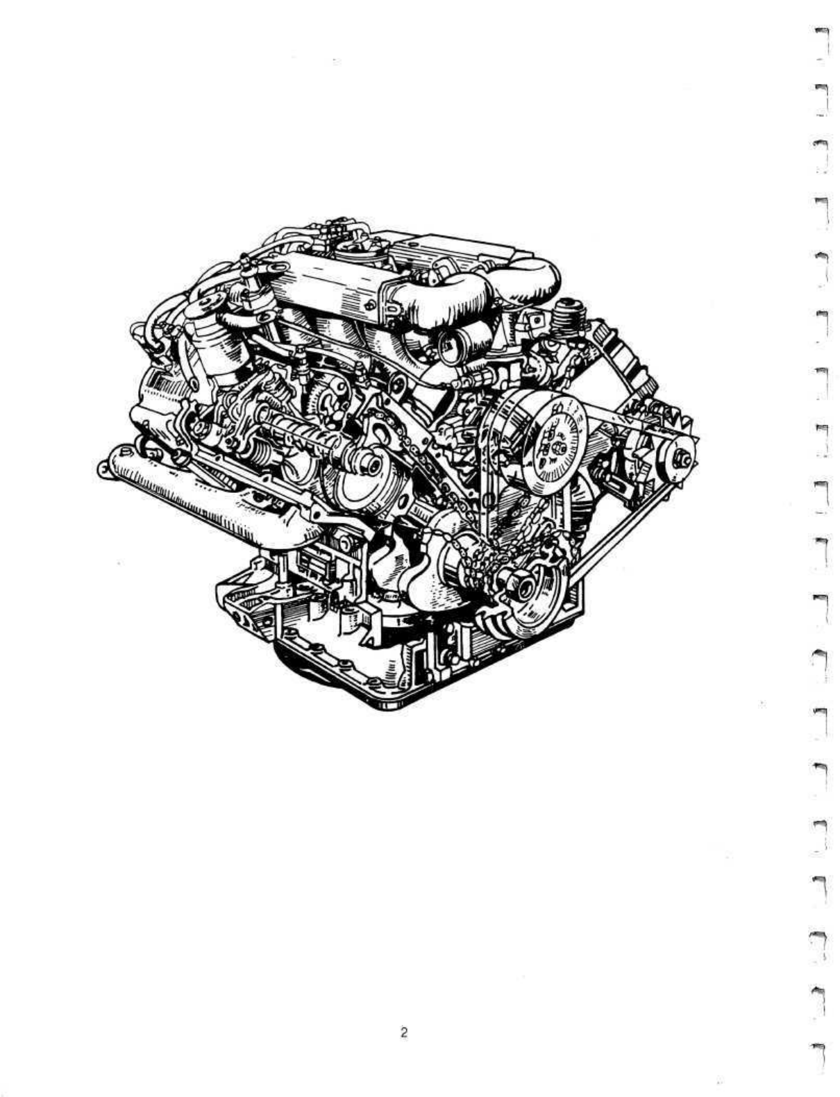
TheDeLoreanispoweredbya liquidcooled,2.8liter,rearmounted,aluminumalloy
90°V-6uneven-fireenginewithtwo(2)chaindrivenoverheadcamshafts.
Theflywheel(orflexplate)endoftheengineisreferredtoasthefrontoftheengine
duetotheuniquerearenginedesign.Therefore,thetimingcoveranddrivebelt
pul-
leysarelocatedattherearoftheengine.Therightand
leftside
oftheengineisdeter-
minedasviewedstandingattherearofthevehiclelookingintotheenginecompart-
ment.
Enginefiringorderis1,6,3,5,2,4.
The
#1
cylinderislocatedattherightfrontoftheenginefollowedwith#2and#3
cyl-
inders.Cylinder#4islocatedattheleftfrontoftheenginefollowedwith#5and#6
cylinders.
CYLINDERCRANKCASEASSEMBLY:Thecylindercrankcaseassemblyconsistsof
aluminumalloyupperandlowercrankcases.Theuppercrankcasecontainssix(6)
castironcylinderlinersandhousesthecrankshaftwhichissupported
byfour(4)
cast
ironmainbearingcaps.Theuppercrankcasealsocontainsthechaindrivenoilpump
driveanddrivengears.Theoilpumpbodyisa machinedportionoftheuppercrank-
case.
Thelowercrankcaseprovidessideenginemountlocationsandcompletesthe
crankcaseassembly.Thealuminumoilpan,whichhouses
theoil
splashshieldandoil
pickupassembly,issecuredtothelowercrankcase.
CYLINDERHEADS:
The
aluminum
alloy
cross-flow
cylinder
heads,havehemispheri-
calchambersandindividualintakeandexhaustportsforeachcylinder.Boththein-
takeandexhaustvalveguides(8MM)arepressedintothecylinderhead.
NOTE:
CYLINDERHEADRESURFACINGISNOTPERMITTED.
Thesteelvalveseatsarefittedtothecylinderhead.
VALVETRAIN:Eachcylinderheadhasa chaindrivenoverheadcamshaft.The
cam-
shaftoperatesbothintakeandexhaustvalvesoneachbankbymeansofadjustable
rockerarmsmountedona single,commonrockershaft.Therockerarmsare
posi-
tionedandheldinplacebymeansoftwo(2)spacersandone(1)thrustspringper
cylinder.
Thehollowrockerarmshaft,whichalsodistributesengineoilthroughcalibrated
holestothevalvetrainandcamshaft,ismountedandsecuredtoeachcylinderhead
withfour(4)rockershaftsupports.
CAMSHAFTANDDRIVE:Eachchaindrivencastironcamshaftissupportedatfour
(4)contactareas.Steelcrankshaftsprocketsdrivethetimingchains(2)whichinturn
*1
drivethecamshaftsprockets(2).J
PISTONSANDCONNECTINGRODS:Eachaluminumalloypistonusestwo(2)com-
_
pressionringsandone(1)oil
ring.
Thesteelpistonpinhasa floatingfitinthepiston.
Thepinsareretainedintheconnectingrodbya hot'pressfit.Theconnectingrod
bearingsarelubricatedviadrilledoilpassageslocatedinthecrankshaftjournals.
CRANKSHAFT:Thecastironcrankshaftissupportedwithfour(4)mainbearingsand
mainbearingcaps.Thisunevenfireenginecrankshafthasthree(3)connectingrod
journals.Lubricationfortheconnectingrodjournalisdeliveredviadrilledoilpas-
sagesinthecrankshaft,crankshaftmainbearingsandmainbearingjournals.The
crankshaftissealedateachendwitha lip
seal.
Therearethree(3)steeldrivesprocketsmountedonthe
rearof
thecrankshaft.These
three(3)chainsprocketsdrive:
-rightcamshaftsprocket
-leftcamshaftsprocket
-oilpumpsprocket
Thedrivechainsandsprocketsarecoveredbyatimingchaincoverwhichissecured
totheupperandlowercrankcaseassembly.
ENGINECOOLING:Thevehicle
has
two(2)electric
fans
forradiatorcoolingmounted
atthefrontofthevehicle.Thesefansareactivatedwhentheenginecoolanttempera-
tureexceeds
97°C (206°
F)anddeactivatedat
91°C (195°F)
Operationofthesefans
iscontrolledbyatemperatureswitchlocatedonthecoolantreturnpipeintheengine
compartment.
Thewaterpump,locatedattherearoftheengine,isbeltdrivenbythecrankshaft
pul-
ley.Thethermostatishousedinthetopofthewaterpumpunderthethermostathous-
ingcover.Thethermostathousingcoverisequippedwithanairbleedscrewusedto
purgetheairfromthecoolantsystemwhenrefilling.
Coolantleavingtheengineisdirectedthrougha seriesofpipesandhosecouplings
alongthe
leftside
of
the
vehicle
center
tunneltotheradiator.Coolantleavingthe
radi-
atorisdirectedthrougha seriesofpipesandhosecouplingsalongtherightsideof
thevehiclecentertunneltotheengine.
Thecoolantexpansiontank(fillpoint)locatedontherightsideoftheenginecom-
partment,isconnectedtothecoolantreturnpipebya hose.
psft
^•Tr>
fn-?\
i
TRANSMISSION- MANUAL
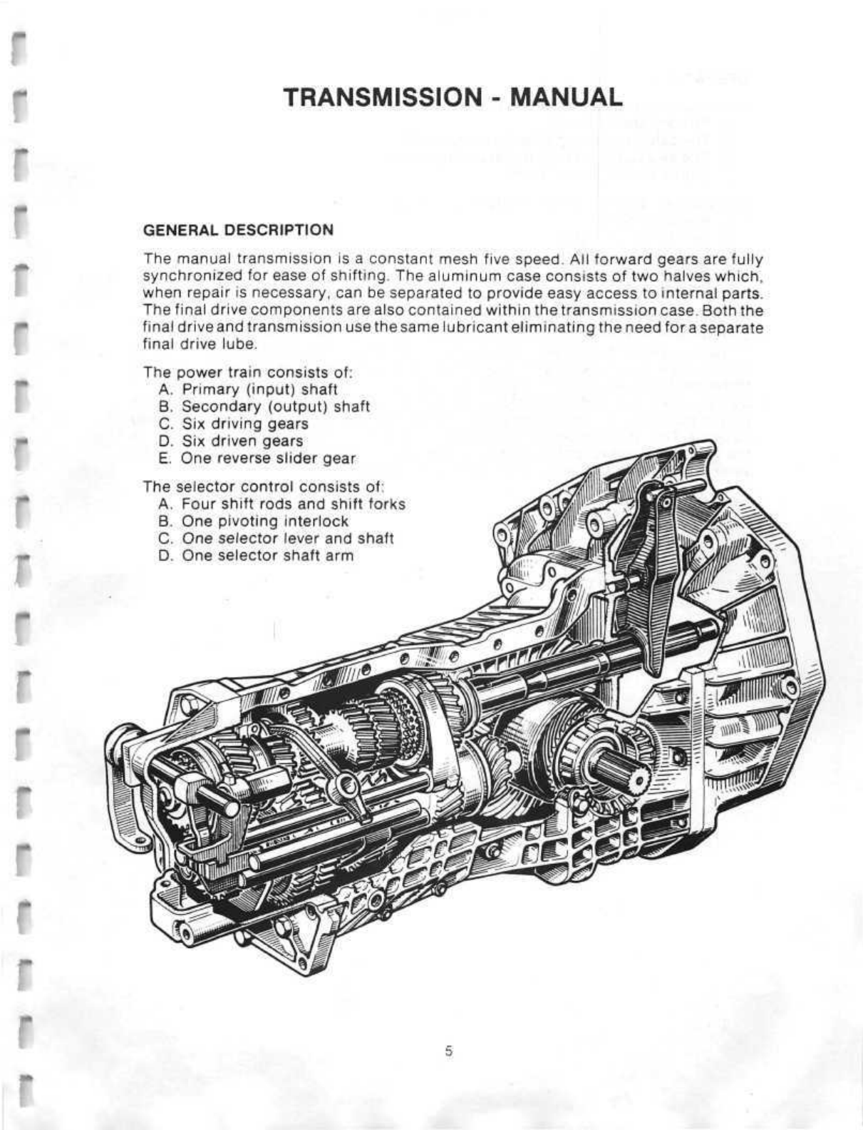
GENERALDESCRIPTION
Themanualtransmission
is
a constantmeshfivespeed.Allforwardgearsarefully
synchronizedforeaseofshifting.Thealuminumcaseconsistsoftwohalveswhich,
whenrepairisnecessary,canbeseparatedtoprovideeasyaccesstointernalparts.
Thefinaldrivecomponentsarealsocontainedwithinthetransmissioncase.Boththe
finaldriveandtransmission
usethe
same
lubricanteliminating
theneed
fora
separate
finaldrivelube.
Thepowertrainconsistsof:
A.Primary(input)shaft
B.Secondary(output)shaft
C.Sixdrivinggears
D.Sixdrivengears
E.Onereverseslidergear
Theselectorcontrolconsistsof:
A.Fourshiftrodsandshiftforks
B.Onepivotinginterlock
C.One selector leverandshaft
D.Oneselectorshaftarm
OPERATION
Allforwardgearpowerflowistransferredvia:
\
A.Primaryshaft(input)
B.Theselecteddrivinggear(primaryshaft)
C.Theselecteddrivengear(secondaryshaft)
**|
D.Pinionshaft/finaldriveuniti
Reversegearpowerflowistransferredbymeansof:
A.Primaryshaft
*"|
B.Reversedrivinggear
_'
C.Reverseslidergear
D.Reversedrivengear
^
E.Pinionshaft/finaldriveunitj
Allgearsareselectedmanuallybythedriverusingthegearshiftleverattachedtothe
selectorlevermountedonthesideofthetransmissionrearhousing.Insidetherear
<SI)
housing,
a selectorshaftarm,attachedtotheselectorshaft,fitsthrougha slotinthe
_!
pivotinginterlock.Whena gearisselected,theselectorshaftarmmovestheinterlock
to
thedesiredpositionandmovestheappropriateshiftrodin
or
outdependingonthe
gearselected.Theshiftforkattachedtotheshiftrodmovesthedesiredgearintothe
properpositionwhilethesychronizerringmatchesthespeedofthetwogearsbeing
coupled.
Thisshiftsequenceisrepeatedforallforwardgears.Reverseoperationis
the
samewiththeexceptionofthesynchronizer
ring,
whichisnotrequired,
since
the
vehicleshouldbestationarywhenshiftingtoreverse.
Gearratiosareasfollows:
1stGear:
2ndGear:
3rdGear:
4thGear:
5thGear:
ReverseGear:
3.36
2.06
1.38
1.06
0.82
3.18
H
j
,K"..|
CLUTCH
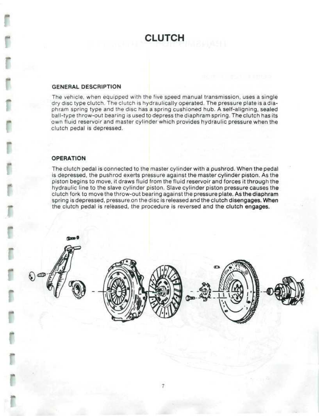
GENERALDESCRIPTION
Thevehicle,whenequippedwiththefivespeedmanualtransmission,usesa single
drydisctypeclutch.Theclutchishydraulicallyoperated.Thepressureplateisadia-
phram
springtypeandthedischasa springcushionedhub.A self-aligning,sealed
ball-typethrow-outbearingisusedtodepressthediaphramspring.Theclutchhasits
ownfluidreservoirandmastercylinderwhichprovideshydraulicpressurewhenthe
clutchpedalisdepressed.
OPERATION
Theclutchpedalisconnectedtothemastercylinderwitha pushrod.Whenthepedal
isdepressed,thepushrodexertspressureagainstthemastercylinderpiston.Asthe
pistonbeginstomove,itdrawsfluidfromthefluidreservoirandforcesitthroughthe
hydrauliclinetotheslavecylinderpiston.Slavecylinderpistonpressurecausesthe
clutchforktomovethethrow-outbearingagainstthepressureplate.
As
thediaphram
springisdepressed,pressureonthediscisreleasedandtheclutchdisengages.When
theclutchpedalisreleased,theprocedureisreversedandtheclutchengages.
(5a>»
r
r
r
-
I
r
r
©
<£D3J>-

TRANSMISSION- AUTOMATIC
GENERALDESCRIPTION
Thethree(3)speedautomatictransmissionusesa conventionaltorqueconverter.
Thisconverterhas
a
singlestatorsupportedon
a
one-wayrollerclutch.Thefinaldrive
unitiscontainedwithinthetransmissioncase.Gearreduction,directdrive,and
reverseareachievedusingone
(1)
planetarygearset,two(2)reactionmembers,and
two(2)internalclutchpacks.Hydraulicpressureforthistransmissionisdeveloped
withacrescent
geartype
oilpump.
The
pumpisdrivenby
a
shaftwhich
runs
theentire
lengthofthetransmissioncase.Thisshaftissplinedtotheconverterandturnsat
enginespeed.Mainlinepressureisregulatedbya pressureregulatorvalveanda
vacuumoperatedactuator.Asenginevacuum
decreases,
thevalveincreasesmain
linepressuretoassurepositiveapplicationoftheclutchesandreactionmembers.
Theshiftvalves
in
thevalvebodyarecontrolledbya computergovernorassembly
andtwo(2)electricsolenoids.Bycomparison,a conventionalvalvebodyusesa
mechanicalgovernorand
a
vacuummodulator(orthrottlevalve)toperform
this
same
function.
Thevalvebodyisnotservicableandmustbereplacedasa unitifrequired.
Thehydraulictransmissionisoperatedandlubricatedbyautomatictransmission
fluidwhilethefinaldriveassemblyisina separateareafilledwithgearlube.
1
!
1
1
1

FRONTSUSPENSION
i'!i.-f
GENERALDESCRIPTION
Thefrontsuspensionisa fullyindependenttypewithupperandlowercontrolarms,
stabilizerbarandsteeringknuckleassembly.Telescopicshockabsorbers,securedto
thechassisframetowerattheabsorber'supperendandtothelowercontrolarmat
theabsorber'slowerend,arepositionedthroughthecoilsprings.
Thesinglefronthubbearingsupportsthehubassemblyonthespindlewhichis
fastenedtothesteeringknuckle.Thesteeringknuckleissecuredtotheupperand
lowercontrolarmswithupperandlowerballjointsandtothesteeringsystemwithan
adjustableball-typetierod.
r
REARSUSPENSION
GENERALDESCRIPTION
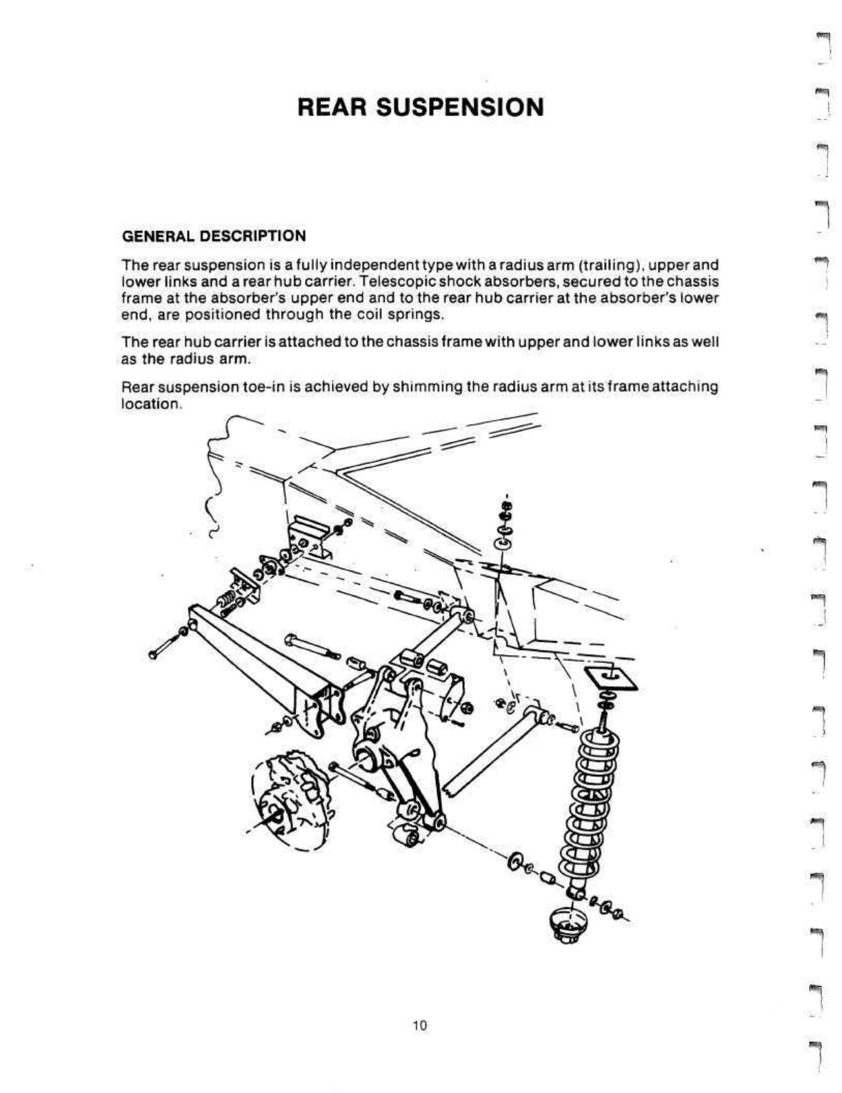
Therearsuspensionisafully
independenttypewitharadius
arm(trailing),
upper
and
lowerlinksanda rearhubcarrier.Telescopicshockabsorbers,securedtothechassis
frameattheabsorber'supperendandtotherearhubcarrierattheabsorber'slower
end,
arepositionedthroughthecoilsprings.
Therearhubcarrierisattachedtothechassisframewithupperandlowerlinksaswell
astheradiusarm.
Rearsuspensiontoe-inisachievedbyshimmingtheradiusarmatits
frame
attaching
location.
I• :
P-^]
10
r^'-'j

STEERING
f'^V
r
GENERALDESCRIPTION
Thesteeringsystemconsistsofa collapsiblesteeringcolumnassembly,aninter-
mediateshaftassemblyanda rackandpiniontypesteeringunit.
Thesteeringcolumnassemblyissupportedinthepassengercompartmentwithan
adjustable(upanddown)bracket.Eachendofthesteeringcolumnshaftissplined.
Theuppersplinedendisdesignedtoacceptthesteeringwheel.Thelowersplined
endofthesteeringcolumnshaftfitsthroughanopeninginthedriver'sfootwelland
issealedwitha gasketandplate.
Thelowerendofthesteeringcolumnshaftissecuredtotheupperuniversaljointof
theintermediateshaft.Theloweruniversaljointoftheintermediateshaftissecured
tothesplinedstubshaftofthesteeringgear.
Thesteeringunitconsistsofa rackandpinionassembly,tierodassembliesandtie
rodends.Eachendoftherackandpinionassemblyisprotectedfromtheelements
witha flexiblerubberbootwhichissecuredwithtwo(2)clamps.Theadjustabletie
rodends,forobtainingpropertoe-inspecifications,arefastenedtothesteering
knuckles.
I'M
•*?
11
r

BRAKES
GENERALDESCRIPTION
Thevehicleisequippedwitha fourwheel,vacuumassisted,hydraulicdiscbrake
system.
Thediscbrakesareappliedwithseparatefrontandrearhydrauliccircuits.
Thehydraulicpressureforthesecircuitsoriginatesata tandemmastercylinder
whichisoperatedwithpushrods.Brakeapplicationisassistedwiththeaidofa
mechanical/vacuumpowerservounitwhichisactivatedbybrakepedalapplication.
Theparkbrakemechanicallyoperatestherearbrakesonly.
Eachwheelassemblyisequippedwitha fixedcalipercontainingtwoopposingpis-
tons(attachedtoknuckleorcarrier),a brakedisc(positionedoverthehubandwheel
studs)anda setorbrakepads.
Inadditiontotheservicebrakecalipersandpads,therearbrakesareequippedwith
independentandseparateparkbrakecaliperandpadassemblies.Theparkbrake
calipersandpadsareoperatedwiththeparkbrakeleverinsidethedriver's
compartmentbymeansoftwo(2)separatecablestoprovideparkandemergency
braking
ofthereardiscs.Theparkbrakecaliperandpadassembliesaresecuredto
therearservicebrakecalipers.Theparkbrakecaliperandpadassembliesareself-
adjustingbymeansofa springloadedrachetingpawlincorporatedwithinthecaliper
applylever.
Thetandemmastercylinderconsistsoftwo(2)independentcylindersina single
casting.
Shouldonecylinderorsystem
fail,
theothersystemwillremainoperational.
Eachhydraulicsystem(frontandrear)hasa separatebrakefluidsupplywellinthe
brakefluidreservoirwhichismountedtothetopofthemastercylinder.Thebrake
fluidreservoirisequippedwitha floatactuated,lowfluidwarningindicator.
However,thissystemisnotequippedwitha lowpressureindicator,a meteringvalve,
proportioningvalveora combinationofthesevalves.
1
1
•
•
*
•
Thepowerassistfromthebrakeservounitisdevelopedbyenginevacuum.Engine
vacuum,
obtainedfromanintakemanifoldfitting,isappliedtobothsidesofa
diaphragminsidetheservounit.Depressingthebrakepedalwillallowatmospheric
pressuretoenteronesideofthediaphragm.Thisdifferenceinpressuredevelopsthe
powerassistusedinapplyingthebrakesystems.Theservounitislocatedbetween
thebrakepedalandmastercylinder.Theapplypressureistransferredthroughtwo
(2)in-linepushrods.Should
a
vacuumfailureoccur,thetwo(2)push
rods
will
actas
a
singlerodandthebrakeswillcontinuetooperateintheunassisted,conventional
manner;however,additionalbrakepedaleffortwillberequired.A vacuumcheck
valveisusedinthesupplylinewhereitconnectstotheservounit.Thischeckvalve
preventsvacuumlossfromtheservounit
after
theenginestopsrunningandprovides
enoughvacuumreserveforemergencybrakeapplication.
1
1
1
12
HEATINGANDAIRCONDITIONINGSYSTEM
r
r
/fr?*
GENERALDESCRIPTION
Thevehicleuses
a
dual-functionairconditioningsystemwhichprovidesbothheating
andcooling.TheairconditioningsystemistheCyclingClutchOrificeTubetype
(C.C.O.T.).Thissystemusesa pressuresensingswitchtopreventevaporatorfreeze-
upbycyclingthecompressoronandoff.Heatingiscontrolledbytheamountofair
flowthroughtheheatercore.Thisflowiscontrolledbya temperaturedooroperated
witha cableconnectedtothetemperatureknob.
OPERATION
CONTROLFUNCTIONS:Airisdrawnintothesystembya faneitherthroughthe
freshairintake(locatedjustaheadofthewindshield),orfromtheinterioroftheve-
hicledependingonthepositionofthere-circulationdoor.Thefanthenforcestheair
throughtheevaporatorcoretothetemperaturedoor.Thepositionofthetemperature
doorcontrolstheamountofsystemairdirectedthroughtheheatercore.Twomode
doors(mountedona commonshaft)directtheconditionedairtoeitherthefootwell/
windshieldchamberorthedoor/facelevelventchamber,or
both.
The
footwell/wind-
shieldchambercontainsa horizontallymounteddoorwhichdirectstheconditioned
aireithertothewindshieldorthefootwell.Thedoor/facelevelventalsocontainsa
horizontallymounteddoorwhicheithershutsofffacelevelventsorshutsoff
a
bridg-
ingductconnectingwiththewindshieldvent.
Alldoors,withtheexceptionofthecableoperatedtemperaturedoor,arevacuum
operatedbydiaphragmactuators.Theairconditioning/heaterselectorswitchhas
twofunctions.Onefunctionistosupplyvacuumtothecorrectdooractuators.The
other
function
istosupplyelectriccurrenttotheairconditioningcompressorandthe
blowerfanasnecessarywhenthedifferentpositionsareselected.
Thecontrolofvacuumdistributionisachievedbymeansofa five(5)portrotaryvalve.
Therotationofthisvalveiscontrolledbyair
conditioning/heater
selectormovement.
Avacuumhoseharnessconnectsalldoorvacuumactuatorstotheairconditioning/
heaterselector.Thevacuumhoseharnessalso
delivers
theoperatingvacuumsource
tothe
five-port
rotaryvalve.Vacuumforthissystem'soperationissuppliedbyengine
vacuumandstoredina vacuumreservoirtank(locatedintheleftrearbodysection).
13

Reservoirtankvacuumismaintainedaftertheengineisshutoffbymeans
of
vacuum
supplylinecheckvalve.Asthefive(5)portrotaryvalveisturned(byselectormove-
ment),variousvacuumportswillaligntoeitherventorsupplyvacuumtotheproper
actuatorsrequiredforthedesiredoperatingmode.
Theconnectionandswitchingsequenceoftheselectorswitchisasfollows:
^59
VACUUMCONNECTIONS
Port2 - Black/Brown
LowerModeDoor
Port1 - Black
Supplyfrom
Reservoir
SELECTORROTARYVALVE
Port3 - Black/Orange
RecirculationDoorand
WaterValve
Port4 - Black/Blue
WindshieldVentDoor
Port5 - Black/Red
UpperModeDoorandFaceLevel
VentDoor
y*^v~;i
VACUUMSWITCHING
SELECTORCONTROLPOSITION
CONNECTION
1Source
2Lowermodedoor
3Re-circulationdoor
&watervalve
4Windshielddoor
5Uppermodedoor&
facelevelvent
OFF
Seal
Vent
Vent
Vent
MAX
Vac
Vac
Vac
Vent
NORM
Vac
Vac
Vent
Vent
BI-LEVELVENT
Vac
Vent
Vent
Vent
Vac
Vac
Vent
Vent
HEATER
Seal
Vent
Vent
Vent
DEFROST
Vac
Vent
Vent
Vac
VentVacVacVacVacVentVent
14
Table of contents
Other Delorean Automobile manuals


