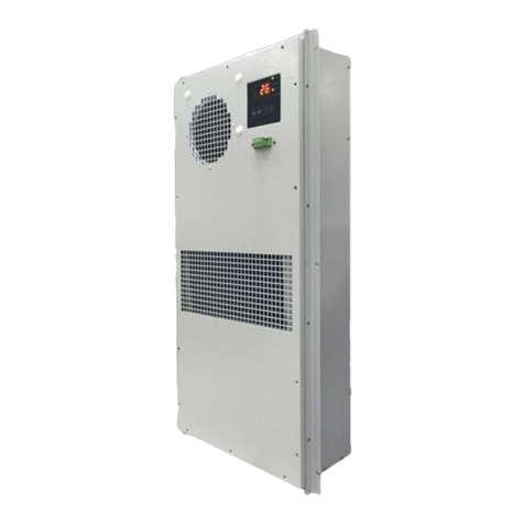
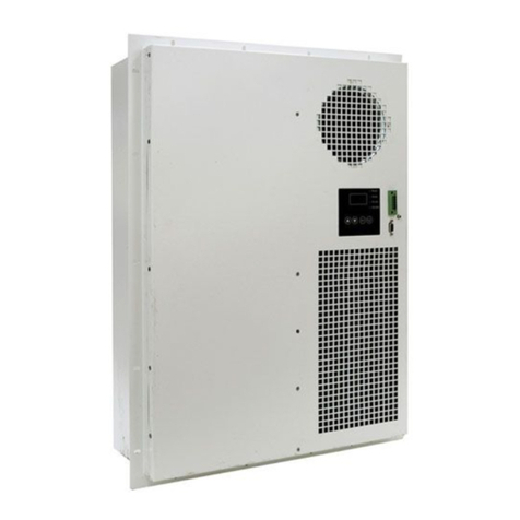
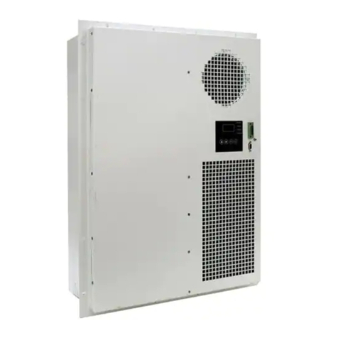
Delta Electronics HEC1500PB User manual

Specification and Manual
Customer :
Description : Air Conditioner for Equipment (Through Wall Mounting)
CustomerPartNo.: Rev.:
Delta Model No. : HEC1500PB Rev:
Sample Date Code:
Sample Issue Date :
DELTA ELECTRONICS, INC.
252, SHANG YING ROAD, KUEI SAN TEL : 886-(0)3-3591968
TAOYUAN CITY 333, TAIWAN FAX : 886-(0)3-3591991
Please send one copy of this specification back after you
signed approval for production pre-arrangement
Approved by :
Date :

Part no. :
Delta model no. : HEC1500PB
Page 2
Table of content
Description...........................................................................................................................4
Packing & Shipping .............................................................................................................4
Safety Notes ........................................................................................................................4
1. Product Instruction........................................................................................................8
1-1. General Description...............................................................................................8
1-2. Main Feature & Model Number .............................................................................8
1-3. Dimension ...........................................................................................................10
1-4. Mounting Panel Cutout........................................................................................ 11
1-5. Configuration & Maintenance .............................................................................. 12
1-6. Thermal and Airflow............................................................................................. 13
2 Electrical Specification................................................................................................ 14
2-1. Indicator & Connector..........................................................................................14
2-1-1 Power Supply & Alarm Connector.............................................................. 14
2-1-2 Protection................................................................................................... 15
3. Environmental Condition ............................................................................................17
3-1. Operating Temperature .......................................................................................17
3-2. Storage Temperature...........................................................................................17
3-3. Operation Humidity.............................................................................................. 17
3-4. Ingress Protection Rating ....................................................................................17
4. Reliability Table...........................................................................................................17
5. Safety Certification .....................................................................................................17
6. Accessory...................................................................................................................18
7. Parameters Table .......................................................................................................18

Part no. :
Delta model no. : HEC1500PB
Page 3
7-1. System Setup......................................................................................................18
7-2. Alarm Logs & Fault Processing ...........................................................................19
8. Installation Notice .......................................................................................................21
9. Warranty .....................................................................................................................21
10. Reclaim ...................................................................................................................... 21

P
D
P
art no. :
D
elta mod
Descrip
t
Thi
s
unit, ple
a
exclusiv
without
p
Packing
Du
r
tilt and
c
not sta
n
packag
e
If ai
for 12 h
alarm h
a
noise.
Safety
N
Ple
a
correctl
y
operati
o
Meaning
W
F
C
F
w
el no. : H
E
t
ion
s
document
a
se read thi
s
v
e property
o
p
rior permis
s
& Ship
p
r
ing handlin
g
c
ollision.
A
ir
c
n
d on the b
o
e
.
i
r conditione
r
ours to ens
u
a
ppened, c.
N
otes
a
se read th
e
y
. After com
p
o
n.
of WARNIN
G
W
arning:
F
ailure to foll
o
C
aution:
F
ailure to o
b
w
hich may b
e
E
C1500PB
is an install
a
s
manual th
o
o
f Delta Ele
c
s
ion of Delta
p
ing
g
or transpor
t
c
onditioner i
o
x, or place
r
is toppled,
u
re refrigera
air conditio
n
e
safety note
s
p
leting the in
s
G
and C
A
U
T
o
w these in
s
b
serve these
e
serious de
p
a
tion and th
e
o
roughly, an
d
c
tronics, Inc.
. Specificati
o
t
, air conditi
o
s
a precisio
n
heavy obje
c
o
ver slanted
nt pressure
n
er keeps 1
s
carefully b
e
s
tallation, m
a
T
ION notice
s
s
tructions pr
o
instruction
s
p
ending on t
Page 4
e
characteris
t
d
following th
it should n
o
o
ns are subj
e
o
ner must b
e
n
instrument
,
c
ts on it. Pl
e
d
or dropped
stability, b.
hour operati
e
fore installi
n
a
ke sure tha
t
s
:
o
perly may r
e
s
properly
m
t
he circumst
a
t
ics of Delta
e instruction
o
t be distrib
u
e
ct to chang
e
e
upward pl
a
,
it should b
e
e
ase pay at
t
unfortunatel
p
ower on a
n
ng and mak
n
g air condit
i
t
the unit op
e
e
sult in pers
o
ay result in
a
nce.
HECX1P s
e
s contained
ted, reprod
u
e
without no
t
ced, “NO”
e
handled or
t
ention to t
h
y
, please fol
l
n
d execute
s
e
sure ther
e
oning unit a
n
e
rates prope
o
nal injure o
r
property da
e
ries. Before
in it. The do
c
u
ced, or any
t
ice.
inverted, fl
transported
h
e following
low below s
t
s
elf-test to
m
e
is no abno
r
n
d be sure t
o
e
rly during th
e
r loss life.
a
mage or p
e
installing th
e
c
ument is th
e
other form
a
a
t, excessiv
e
with care, d
o
icons on th
e
t
eps: a. stan
d
m
ake sure n
o
r
mal acousti
c
o
install it
e
start-up
rsonal injur
y
e
e
a
t
e
o
e
d
o
c
y
,

Part no. :
Delta model no. : HEC1500PB
Page 5
Warming:
1. Installation work and electrical wiring must be done by qualified person(s) in accordance with all
applicable codes, standards and national wiring regulations.
2. Use this unit only in the manner intended by the manufacturer. If you have questions, please contact the
manufacturer.
3. Install the air conditioner in accordance with the instructions in this installation manual. Improper
installation may result in water leakage, electric shocks or fire.
4. Make sure that all wiring is secured, the specified wires are used, and there is no strain on the terminal
connections or wires.
5. If refrigerant gas leaks during installation, ventilate the area immediately. Do not directly touch refrigerant
that has leaked from refrigerant pipes or other areas, as there is a danger of frostbite.
6. Before serving or cleaning unit, switch power off and disconnect power supply.
7. When cutting or drilling into wall or ceiling, do not damage electrical wiring or hidden utilities.
8. Be sure to use only the specified accessories and parts for installation work.
9. Protective earth connection: The enclosure must be earthed at the protective earth terminal. Use 2.5
mm2(14 AWG) wire and use spring washer to avoid loosening.
10. The air conditioner shall be not accessible to the general public.
11. The installation must contain a device to disconnect all poles of the air conditioner from the power supply.
The contact distance in all poles must be 3 mm minimum.
12. To reduce the risk of electrical shock. Means for disconnection must be incorporated in the fixed wiring in
accordance with the wiring rules.
13. This appliance is intended to be used by expert or trained users in shops, in light industry and on farms,
or for commercial use by lay persons”.
Caution :
1. Install the air conditioner on a wall/ door strong enough to withstand the weight of the unit.
2. Do not allow a child to mount on the outdoor unit or avoid placing any object on it.
3. Do not block air inlets or exits.
4. Do not install the air conditioner at any place where there is a danger or flammable gas leakage.

Part no. :
Delta model no. : HEC1500PB
Page 6
5. Arrange the drain to ensure complete drainage.
6. To avoid injury, do not touch the air inlet or aluminum fins of unit.
7. Watch your steps at the time of fin cleaning or air conditioner inspection.
8. Do not topple the air conditioner while moving or storage.
9. The hole in the bottom of the air conditioner should be connected to a sealed container through a
drainpipe.
10. The appliance is not to be used by persons (including children) with reduced physical, sensory or mental
capabilities, or lack of experience and knowledge, unless they have been given supervision or
instruction.
11. Children being supervised not to play with the appliance.

Part no. :
Delta model no. : HEC1500PB
Page 7
Specification for Approval
Customer :
Description : Air conditioner for Equipment with 1500 W Rated Cooling Capacity (Through
Wall Mounting)
CustomerP/N: Rev.:
Delta model no. : HEC1500PB Rev. :
Sample revision. : Date Code :
Sample issue date : Quantity : one sets
INTERNAL EXTERNAL

Part no. :
Delta model no. : HEC1500PB
Page 8
1. Product Instruction
1-1. General Description
HEC1500PB is a DC air conditioner with 48 VDC power input, it is designed for IP55 sealed outdoor
telecom cabinet to provide stable and optimum internal conditions for equipment and avoid hotspot inside
the cabinet.
HEC X1 P
(1) (2) (3)
No Item Digit Specification
(1) Product Message HEC Compressor Air Conditioner
(2) Cooling Capacity X1 X1=1500
(3) Operation Voltage P DC 48V for door
1-2. Main Feature & Model Number
Dimensions, Weight & Mounting method
Dimension (H x W x D) (without flange) mm (inch) 700 x 500 x 200 (27.7 x 19.8 x 7.9)
Application Outdoor
Weight Kg (lbs) 28.0 (61.7)
Mounting Method Door/Side
Color (optional) RAL7035
Environmental Protection & Performance
Operating Temperature Range °C (°F) -10 to +55 (+14 to +131)
Operating Humidity External : 0~100% RH
Internal: 0~80% RH
Storage Temperature °C (°F) -40~ +70 (-4~ +158)
Storage Relative Humidity RH 5~95%
Refrigerant R134a, 285 g±10 g
Protection for Dust ,Wind and Water (External) IEC 60529 /GR487 IP55 / GR487
Noise (1m) dB-A 65
Operating Status N/A LED Indicator / Display Board
Cooling Capacity & Operational Data
Rated Cooling Capacity at L35/L35 W (Btu/hr) 1500 (5100)
Rated Cooling Current A 12.5
Rated Internal Airflow (L35/L35) m3/h (CFM) 420 (250)
Rated External Airflow (L35/L35) m3/h (CFM) 470 (275)
Power & Range
Input Voltage VDC 48

P
D
P
art no. :
D
elta mod
Max. Opera
t
Alarm
Controller
Fans
Compresso
r
el no. : H
E
t
ing DC Cur
r
r
E
C1500PB
r
ent
K
e
Page 9
A
N/
A
e
y Compone
A
nts
Dry
Built-i
n
Delta Hi
g
14.3
Contact Ou
t
n
Smart Co
n
g
h Efficiency
Rotary, DC
t
pu
t
troller
Blowers

Part no. :
Delta model no. : HEC1500PB
Page 10
1-3. Dimension
(1) Material: Case SGCC Sheet.
(2) Finish: Powder coating 75~120 uM, Color RAL 7035.
(3) Dimensional Tolerance: ±1 mm.

Part no. :
Delta model no. : HEC1500PB
Page 11
1-4. Mounting Panel Cutout
Inside
Outside
Gasket

Part no. :
Delta model no. : HEC1500PB
Page 12
1-5. Configuration & Maintenance
Make sure the air conditioner surface sealed with mounting flange to avoid water penetrates into
shelter through mounting interface. It is suggested to use gaskets sticking on the mounting flange and seal
the gap between flange and cabinet with silicone gel during installation. There should be NO any gap
surround gaskets to avoid water penetrates into enclosure.
The air conditioner is composed as the following key components: they are chassis, cover, controller,
heat exchanger, blowers and compressor etc. It is “not” recommended that the user replace the
compressor, evaporator, and the condenser by themselves; it may damage the system and getting injured.
In order to assure the air conditioner running at optimal condition, the condenser should be cleaned
once annually at least; user can clean the condenser with water directly. The external side fan blade can
also be cleaned with normal pressure water if there is dust accumulation. Please do not use strong water
jet to impact the center of fan and the surface of condenser.
The bottom hole of the air conditioner should be connected to a sealed container through a drainpipe,
please clear drain holes when the maintenance. Please also notice that:
1. Check wires are connected correctly, and the insulation is not cracking or broken.
2. Use Self-test to check the unit running correctly or not. And the supplied air of internal side should be as
cooled air.
3. Do not wipe the product with organic solvent, volatile substances like toluene or gasoline, it will destroy
the powder-coated surface.
4. Turn off the power before maintaining.
5. Please turn off power and remove dry contact connector while non-operating for a long time.
NO. Q'TY DESCRIPTION
1 1 Case Chassis
2 1 Case Cover
3 1 Control Board
4 1 DC Power Board
5 1 Evaporator
6 1 Internal Fan
7 1 Condenser
8 1 External Fan
9 1 Compressor

P
D
P
art no. :
D
elta mod
6. If any
with c
u
7. The r
e
allow
e
hours
8. The c
o
disma
n
1-6. Th
e
Th
e
design
cabine
tempe
r
Th
evapo
r
el no. : H
E
abnormal a
c
u
stomer ser
v
e
frigerant is
e
d for applic
a
to make sur
e
o
mpressor
e
n
tle the seal
e
e
rmal an
d
e
internal an
, internal a
n
t to the am
b
r
ature meas
u
e waste hea
r
ator and dis
s
E
C1500PB
c
oustic nois
e
v
ices.
environme
n
a
tion. If refri
g
e
the refrige
r
e
lectrical pr
o
e
d cover or
w
d
Airflow
d external a
n
d external
a
b
ience. Inter
u
rement and
t generated
f
s
ipate to the
e
from air c
o
tal friendly
p
g
erant leaka
g
r
ant fully ex
h
o
tecting cov
e
w
ill lose the
q
ir flow circul
a
ir flow won’
t
n
al tempera
t
safety of o
p
f
rom the int
e
ambience
b
Page 1
3
o
nditioner h
a
p
roduct of
R
g
e seriously
,
h
aust. Pleas
e
e
r is sealed
q
uality assu
r
l
ation is sho
w
t
be mixed
s
ture sensor
p
eration.
e
rnal equipm
e
b
y the conde
n
3
a
ppened, pl
e
R
134a. Little
,
please tur
n
e
also conta
c
with silicon
r
ance of the
w
n as the fi
g
s
ince the w
a
is placed a
t
e
nt will be a
b
n
ser of exte
r
e
ase turn of
f
refrigerant
n
off the po
w
c
t the servic
e
for IP55 re
q
c
ompressor.
g
ure. Throu
g
a
ste heat ca
return air s
b
sorbed by t
h
r
nal side.
f
the produc
t
leakage (<
w
er and wait
e
s to replac
e
q
uirement.
P
.
g
h separate
d
n be dissip
a
s
tream to pr
o
h
e refrigera
n
t
and conta
c
5 g/ year) i
s
for at least
2
spare parts
P
lease do n
o
d
mechanis
m
a
ted from th
e
o
vide reliabl
e
n
t through th
e
c
t
s
2
.
o
t
m
e
e
e

Part no. :
Delta model no. : HEC1500PB
Page 14
PIN1
PIN5
2 Electrical Specification
2-1. Indicator & Connector
2-1-1 Power Supply & Alarm Connector
Pin Description Cable wire size
1 DC 14 AWG
2 -48 V 14 AWG
3 N/A N/A
4 N/A N/A
5 N/A N/A
Pin Description
3 Alarm+
4 Alarm-
System alarm default setup
Note: Customers can setup the N.O or N.C by themselves when any alarm happen through display
board (d1.6 Dry-contact Setup).
• Specification:
Contact rating: 60 Vdc, 100mA
• Normal:
PIN 3 and PIN 4 dry contact output close
• Any alarms happening:
PIN 3 and PIN 4 dry contact output open
Case Grounding:
Pin 1
Pin 5
-48V DC

P
D
P
art no. :
D
elta mod
2-1-
2
el no. : H
E
Panel oper
a
• A: Di
s
It will sh
o
• B: LE
D
Power:
Comp.:
Fan (In)
:
Fan (Ou
• C: Pre
s
2 Protectio
n
Over curre
n
DC power
Over temp
e
DC power
Under volta
DC power
Reverse po
E
C1500PB
a
tion
s
play:
o
w the temp
D
indicator:
When the
s
If any alar
m
cause.
When the
c
If the syst
e
:
When the i
t):
When the
o
s
s Buttons:
↑: UP or in
c
↓: DOWN
o
SET: Para
m
ON/OFF E
n
n
t protection:
board: 20
A
e
rature prote
c
board: 95 ±
ge protectio
n
board: 40 ±
larity:
erature insi
d
s
ystem pow
e
m
happens,
a
c
ompressor
i
e
m gets into
s
nner-fan is r
o
uter-fan is
r
c
rease
o
r decrease
m
etric setup
S
C: Power
o
c
tion:
4 oC
n
:
1.4 VDC
Page 1
5
d
e the cabin
e
e
r on and th
e
a
ccording to
is running n
o
s
elf-test mo
d
r
unning nor
m
r
unning nor
m
o
n/off or bac
k
5
e
t and syste
m
e
LED will lig
flashing tim
e
o
rmally and
t
d
e and the L
E
m
ally and the
m
ally and the
k
m
parametri
c
ht in green.
e
s of power l
t
he LED will
l
E
D will flash
LED will lig
h
LED will lig
h
c
setup.
l
ed to check
light in gree
n
in green.
h
t in green.
h
t in green.
the root
n
.

Part no. :
Delta model no. : HEC1500PB
Page 16
Allow reverse voltage: 42 ~ 58 VDC
Short Ckt:
If compressor UVW short for any both phase the compressor will not operate.
Compressor H/T protection
Tcomp ≧105
oC
Eva L/T protection
TEVA < 0 oC
Power on delay for fans & compressor

Part no. :
Delta model no. : HEC1500PB
Page 17
3. Environmental Condition
3-1. Operating Temperature
-10 °C ~ +55 °C (14 °F ~ 131 °F)
3-2. Storage Temperature
-40 °C ~ +70 °C (-4 °F ~ 158 °F)
3-3. Operation Humidity
External air loop: 0 ~ 100 % RH
Internal air loop: 0 ~ 80 % RH, non-condensing
3-4. Ingress Protection Rating
IP55 (IEC60529) on external side
GR487 on external side
4. Reliability Table
Test item Condition
High temperature IEC 60068-2-2
Low temperature IEC 60068-2-1
High temp. / High humidity IEC 60068-2-3
Temperature cycle IEC 60068-2-14 test Nb
Vibration ETSI 300 019-1-4 CLASS 4.1
Ingress protection (external side) IEC 60529 IP55 / GR487
Salt fog test (external side) IEC 60068-2-11 severity 4 , 6cycles
Package bump IEC 60068-2-29
5. Safety Certification
TUV, CE, UL

P
D
P
art no. :
D
elta mod
6.
A
cc
e
Pin
1
2
3
4
5
7. Para
7-1. Sy
s
Item
d1.1
S
d1.2
A
d1.3 I
n
d1.4
A
d1.5
R
d1.6
P
d1.7
P
d1.8
S
d2.1 T
el no. : H
E
e
ssory
Power and
A
Des
c
D
-4
N
N
N
meters
T
s
tem Set
u
S
ystem Versi
o
A
larm Logs
n
side over-t
e
A
uto Self-Te
s
R
ecovery De
f
P
hoto Coupl
e
P
assword
S
ystem Re-l
o
T
arget tempe
E
C1500PB
A
larm Cable
c
ription
D
C
8 V
N
/
A
N
/
A
N
/
A
T
able
u
p
System
P
o
n
e
mp. Setup
s
t Function
f
ault
e
r Normal St
a
o
ck
rature
Cable
w
14
14
P
aramete
r
a
tus
Page 1
8
w
ire size
AWG
AWG
N/A
N/A
N/A
8
De
f
2
0
6
0
En
N
Cl
0
N
3
0
f
ault
2
.5
0
.0
0
oC
a
ble
N
/
A
o
se
00
N
/
A
0
oC
PIN1(+
PIN2(-
)
Ra
n
N
/
N
/
40 oC
-
Enable
/
N
/
Close
/
000
~
N
/
25 oC
-
)
)
n
ge
/A
/A
-
70 oC
Disable
/A
/
Open
~
999
/A
-
40 oC

Part no. :
Delta model no. : HEC1500PB
Page 19
7-2. Alarm Logs & Fault Processing
Alarm Indicators
Flash Times
(Power Led) LV1 Alarm LV2 Alarm Alarm Code
-- --
Compressor 3-min Protection
--Compressor Power Protection
Low-Temp Startup Protection
2 Temperature Abnormal Alarm
Eva Temperature Protection 2.1
Comp-out Temperature Protection 2.2
PWB Temperature Protection 2.3
IPM Temperature Protection 2.4
Amb Temperature Protection 2.5
3 Temperature Sensor Fault
Amb Temperature Sensor 3.1
Eva Temperature Sensor 3.2
Cond Temperature Sensor 3.3
Comp-Out Temperature Sensor 3.4
PWB Temperature Sensor 3.5
IPM Temperature Sensor 3.6
4 Fan Fault
Indoor Fan 4.1
Outdoor Fan 4.2
5 Controller Fault
EEPROM 5.1
Current Sensor 5.2
DC-Bus Voltage 5.3
6 Cooling System Fault
Power Board 6.1
Startup Fail 6.2
IPM Over Current 6.3
Compressor Lack Phase 6.4

Part no. :
Delta model no. : HEC1500PB
Page 20
Fault Analysis and Processing
Fault State Analysis of the Reasons Solutions
Power on, and the cabinet
temperature is too high
but the air conditioner is
not working
1.Power failure or no power.
2.The target temperature is higher
than inside temperature.
3.System failure.
1.Check the power supply and the electric
circuit.
2.Re-set the target temperature according
to the system requirement.
3.Please contact the service department.
The air conditioner is
running but the cabinet
temperature is still high,
no obvious cooling effect.
1.The air conditioner capacity is
not match the load of the system.
2.The ambient temperature is too
high.
3.Low efficiency of the condenser.
4.Other system failure
1.Check the heating load of the system.
2.Ensure the air conditioner operates in
correct temperature range.
3.Clean the condenser.
4.Please contact the service department.
The air conditioner stop
operating, and there is no
alarm signal.
1.The inside temperature is lower
than the target temperature.
2.Other system failure.
1.Re-set the target temperature according
to the system requirement.
2.Please contact the service department.
Other manuals for HEC1500PB
1
Table of contents
Other Delta Electronics Air Conditioner manuals
Popular Air Conditioner manuals by other brands

Hitachi
Hitachi RA-13KF Operation and installation manual

2VV
2VV INDESSE VCIN Series Installation and operation

Mitsubishi Electric
Mitsubishi Electric CITY MULTI PWFY-P100VM-E-BU Operation manual

Mitsubishi Electric
Mitsubishi Electric MSZ-GE60VA operating instructions

LG
LG ZW6510R owner's manual

AERMEC
AERMEC FCXI Series Use and installation manual