Delta Electronics HEC2000XA User manual

Specification and Manual
Customer:
Description: Air Conditioner for Equipment (Through Wall Mounting)
Customer Part No : Rev :
Delta Model No : HEC2000XA Rev : 03
Sample Date Code:
Sample Issue Date: SEP 15 2020
DELTA ELECTRONICS, INC
252, SHANG YING ROAD, KUEI SAN TEL: 886-(0)3-3591968
TAOYUAN CITY 333, TAIWAN FAX: 886-(0)3-3591991
Please send one copy of this specification back after you
signed approval for production pre-arrangement
Approved by:
Date:

Part no :
Delta model no : HEC2000XA
Page 2
Table of content
Description .......................................................................................................................................... 3
Packing & Shipping ........................................................................................................................... 3
Safety Notes ....................................................................................................................................... 3
1 Product Instruction .................................................................................................................... 7
1-1 General Description .......................................................................................................... 7
1-2 Main Feature & Model Number ....................................................................................... 7
1-3 Dimension ........................................................................................................................... 9
1-4 Mounting Panel Cutout ................................................................................................... 10
1-5 Configuration & Maintenance ........................................................................................ 11
1-6 Thermal and Airflow ........................................................................................................ 12
2 Electrical Specification............................................................................................................ 13
2-1 Indicator & Connector ..................................................................................................... 13
2-2 Protection ........................................................................................................................... 16
3 Environmental Condition ........................................................................................................ 16
4 Reliability Table ........................................................................................................................ 17
5 Safety Certification .................................................................................................................. 17
6 Accessory ................................................................................................................................. 17
7 Parameters Table and Something Information ................................................................... 19
7-1 System Parameter Setup ............................................................................................... 19
7-2 System Information Observation .................................................................................. 20
7-3 Panel Operation Flowchart ............................................................................................ 21
7-4 Self-Test (Operating Procedure) ................................................................................... 22
7-5 Alarm Logs & Fault Processing ..................................................................................... 23
8 Installation Notice .................................................................................................................... 26
9 Reclaim ................................................................................................................................... 26
10 Versions .................................................................................................................................. 26
Part no :
Delta model no : HEC2000XA
Page 3
Description
This document is an installation and the characteristics of Delta HECX1P series Before
installing the unit, please read this manual thoroughly, and following the instructions
contained in it The document is the exclusive property of Delta Electronics, Inc it
should not be distributed, reproduced, or any other format without prior permission of
Delta Specifications are subject to change without notice
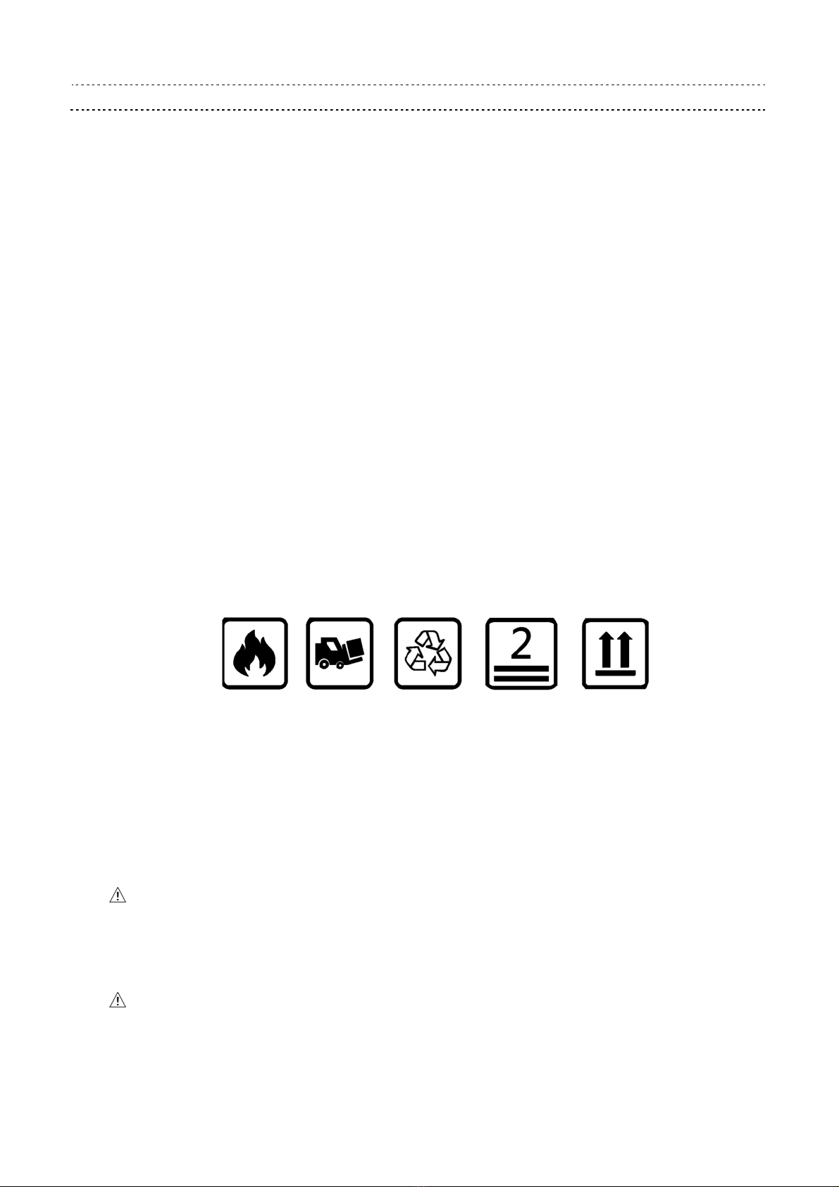
Packing & Shipping
During handling or transport, air conditioner must be kept in upward position, “NOT”
inverted, flat, or subject to excessive tilt and collision The air conditioner is a precision
instrument; it should be handled and transported with care Do not stand on the box,
or place heavy objects on top of the box Pay attention to the below icons on the
package
If air conditioner is toppled, slanted or dropped, follow these steps: a stand unit up for
12 hours to ensure refrigerant pressure stability, b power on the unit and execute
self-test to make sure no alarm condition, c keep the air conditioner running for 1 hour
to make sure there is no abnormal acoustic noise
Safety Notes
Please read the safety notes carefully before installing the air conditioner, and be sure
to install it correctly After completing installation, check that the unit operates properly
during start-up operation
Meaning of WARNING and CAUTION notices:
Warning:
Failure to follow these instructions properly may result in personal injury or loss of
life
Caution:
Failure to observe these instructions properly may result in property damage or
personal injury, which may be serious depending on the circumstance

Part no :
Delta model no : HEC2000XA
Page 4
Warning:
1 Installation work and electrical wiring should be done only by qualified personnel in
accordance with all applicable codes, standards and national wiring regulations
2 Use this unit only in the manner intended by the manufacturer If you have questions,
please contact the manufacturer
3 Install the air conditioner in accordance with the instructions in this installation manual
Improper installation may result in water leakage, electric shock or fire
4 Make sure that all wiring is secured, that specified wires are used, and there is no strain
on the terminal connections or wires
5 If refrigerant gas leaks during installation, ventilate the area immediately Do not directly
touch refrigerant that has leaked from refrigerant pipes or other areas, as there is a
danger of frostbite
6 Before serving or cleaning unit, switch power off and disconnect power supply
7 When cutting or drilling into wall or ceiling, do not damage electrical wiring or hidden
utilities
8 Be sure to use only the specified accessories and parts to complete installation
9 Protective grounding connection: The enclosure must be grounded at the protective
ground terminal Use 6 mm
2
(10 AWG) wire and use spring washer to avoid loosening
10 The air conditioner should not be accessible to the general public
11 The installation must contain a device to disconnect all poles of the air conditioner from
the power supply The contact distance in all poles must be 3 mm minimum
12 To reduce the risk of electrical shock: Means for disconnection must be incorporated in
the fixed wiring in accordance with the wiring rules
13 This appliance is intended for use only by qualified personnel

Part no :
Delta model no : HEC2000XA
Page 5
Caution :
1 Install the air conditioner on a wall or door strong enough to withstand the weight of the
unit
2 Do not block the air inlets or exits
3 Do not install the air conditioner at any place where there is a danger or flammable gas
leakage
4 Arrange the drain to ensure complete drainage
5 To avoid injury, do not touch the air inlet or aluminum fins of the unit
6 Watch your step at the time of fin cleaning or air conditioner inspection
7 Do not topple the air conditioner while moving or in storage
8 The hole in the bottom of the air conditioner should be connected to a sealed container
through a drain pipe
9 This appliance is not to be used by any persons with reduced physical, sensory or
mental capabilities, or lack of experience and knowledge, unless they have been given
proper supervision or instruction
10 Children should be prevented from playing with the appliance
Part no :
Delta model no : HEC2000XA
Page 6
Specification for Approval
Customer :
Description : Air conditioner for Equipment with 2000 W Rated Cooling Capacity (Through
Wall Mounting)
Customer P/N : Rev :
Delta model no : HEC2000XA Rev : 03
Sample revision : Date Code :
Sample issue date : Quantity :
INTERNAL EXTERNAL
Part no :
Delta model no : HEC2000XA
Page 7
1. Product Instruction
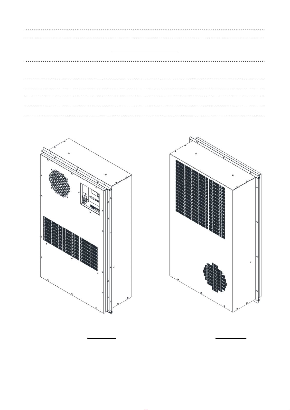
1-1. General Description
HEC2000XA is a DC air conditioner with -48VDC power input, it is designed for IP55
sealed outdoor telecom cabinet to provide stable and optimum internal conditions for
equipment and avoid hotspot inside the cabinet
HEC X1
X
A - XXX
(1)
(2)
(3)
(4) (5)
No Item Digit Specification
(1) Product Message HEC Compressor Air Conditioner
(2) Cooling Capacity X1 X1=2000
(3) Operation Voltage X DC 48 V for door with heater
(4) Product Version A N/A
(5) Customer ID XXX N/A
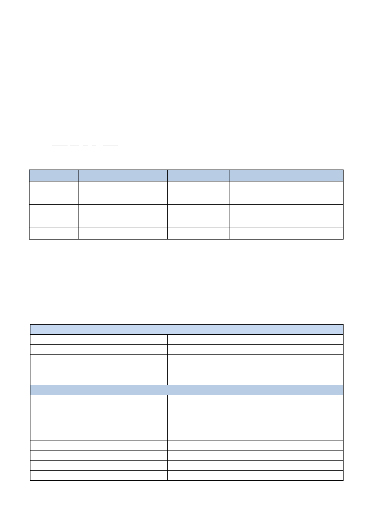
1-2. Main eature & Model Number
Dimensions, Weight & Mounting method
Dimension (H x W x D) (without flange) mm (inch) 746 x 446 x 200 (29 4 x 17 6 x 7 9)
Application Outdoor
Weight Kg (lbs) 37 0 (81 6)
Mounting Method Door/Side
Color (optional) RAL7035
Environmental Protection & Performance
Operating Temperature Range °C (°F) -40 to +55 (-40 to +131)
Operating Humidity External: 0~100% RH
Internal: 0~80% RH
Storage Temperature °C (°F) -40 to +70 (-40 to +158)
Storage Relative Humidity RH 5~95%
Refrigerant R134a, 550 g ±10 g
Protection for Dust ,Wind and Water (External)
IEC 60529 /GR487
IP55 / GR487
Noise (1 5m) dB-A 65
Operating Status N/A LED Indicator / Display Board

Part no :
Delta model no : HEC2000XA
Page 8
Cooling Capacity & Operational Data
Rated Cooling Capacity at L35/L35 W (Btu/hr) 2000 (6800)
Rated Cooling Current A 13 8
Rated Internal Airflow (L35/L35) m
3
/h (CFM) 470 (275)
Rated External Airflow (L35/L35) m
3
/h (CFM) 420 (250)
Heating Capacity (Optional) W 800
Power & Range
Input Voltage VDC 48
Max Operating DC Current A 23
Alarm N/A Dry Contact Output
Key Components
Controller Built-in Smart Controller
Communication port RS485
Fans Delta High Efficiency Blowers
Compressor Rotary, DC
Part no :
Delta model no : HEC2000XA
Page 9
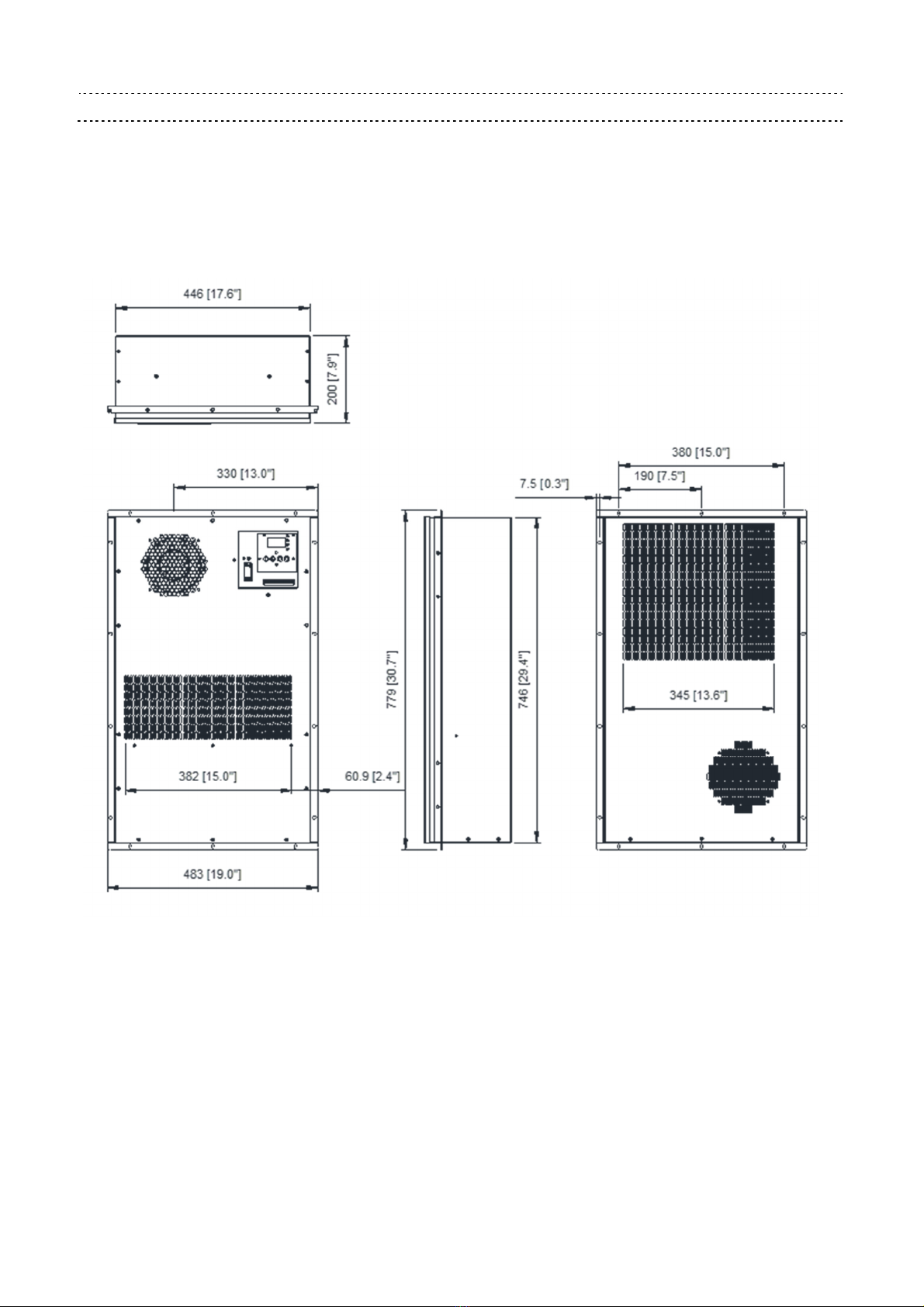
1-3. Dimension
mm (inch)
(1) Material: Case SGCC Sheet
(2) Finish: Power paint 75 ~ 120 um
(3) Color: RAL 7035
(4) Dimension tolerance: ± 1 0mm
Part no :
Delta model no : HEC2000XA
Page 10
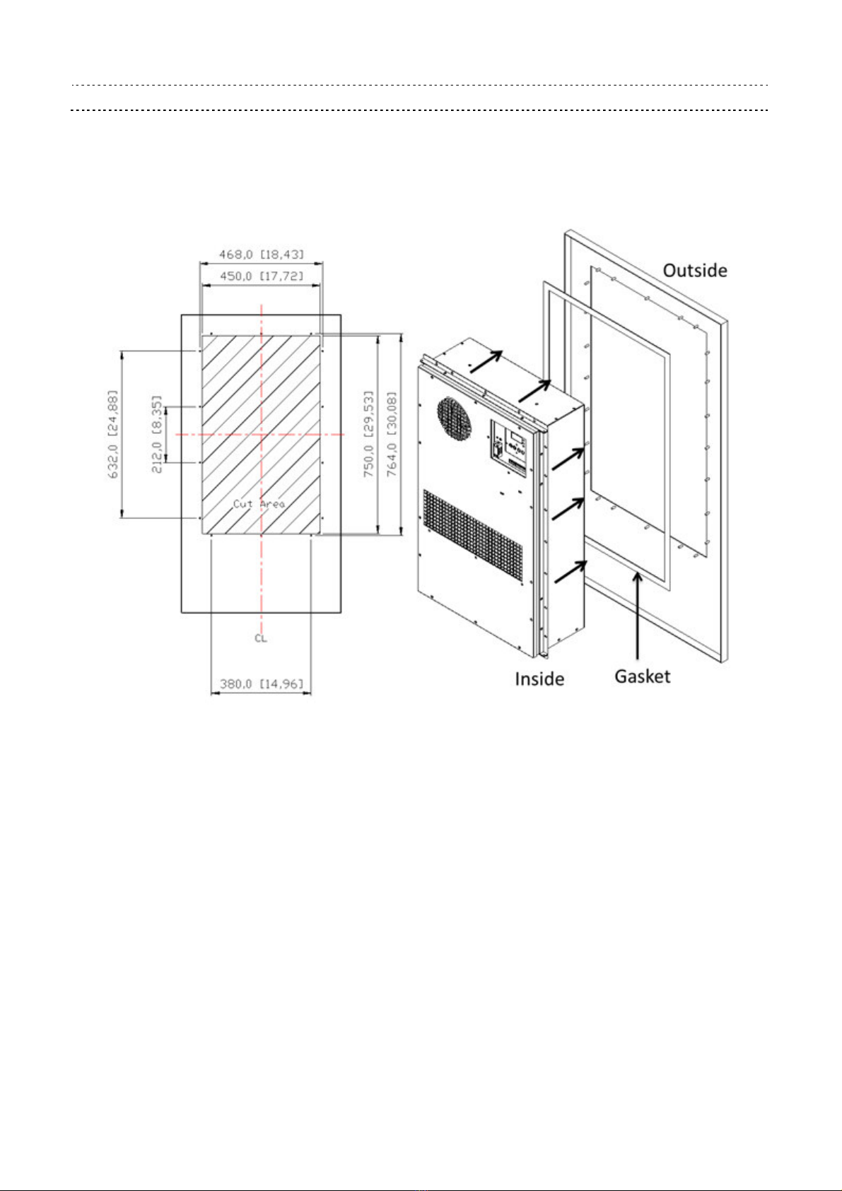
1-4. Mounting Panel Cutout
mm (inch)
Table of contents
Other Delta Electronics Air Conditioner manuals


Popular Air Conditioner manuals by other brands


Fujitsu
Fujitsu Inverter ASBA30JFC operating manual

Toshiba
Toshiba RAS-M10SMUV-E installation manual

Daikin
Daikin FXLQ20MAVE Operation manual

Hitachi
Hitachi RAS-E24CAK instruction manual

CIAT
CIAT Magister 2 Series Installation, Operation, Commissioning, Maintenance

Bestron
Bestron AAC6000 instruction manual


