DELTA GROUP Eltek Flatpack S 332748 User manual

Quick Start Guide
1U Configurations
Wire Feed DC Distribution SELV Alarming (P/N) Dry Contact Alarming (P/N)
Rear Feed
(Load and Battery)
10 GMT Fuses, 2
Plug-in CBs
330180
330179 (no LVBD)
350196
350204 (no LVBD)
Side Feed (Load)
Rear Feed (Battery)
10 GMT Fuses, 2
Plug-in CBs
332748
320056 (no LVBD)
350197
350193 (no LVBD)
Rear Feed
(Load and Battery)
4 Plug-in CBs 350195
350200 (no LVBD)
;
IMPORTANT: Read installation instructions before connecting to supply!
The latest version of this document and other Eltek product documents are available online at
available online at eltek.sharefile.com.
Flatpack S Installation Guides Controller User Guides
Quick Installation Guide: Flatpack S, Doc #356835.103
1U PS Systems
User Guide: Smartpack S Doc #350030.013
Quick Start Guide: Flatpack S PS System Doc #356846.103
(Integrated, Cabinet, Outdoor Applications)
Functionality Description: Doc #350020.073
(Various Eltek Controllers)
Configuration Guide: Doc #350013.063
Smartpack2, Smartpack S,
Compack Controllers
Contact Information
To order parts and request documentation, please contact Sales by email at [email protected] or by phone at
1-469-330-1592.
For assistance with technical questions and solutions, please contact Technical Support by email at
Document 370012.103, Issue 1.4
Published 23-Mar-16
Flatpack S DC System
332748/320056
350197 / 350193
347558/347559
330180/330179
350196 / 350204
ATTACHMENT R & S
BID 15-20: 700/800 MHz EDACS and P25 COMMUNICATIONS SYSTEM
1

2
Quick Start Guide Flatpack S DC System ~ Document 370012.103, Issue 1.4, March 2016
IMPORTANT: READ THIS FIRST
SAFETY NOTICES – DC Power Systems
Read and observe all safety statements and requirements on this sheet before performing any
installation or operation work on the power equipment.
Failure to comply with the safety statements and requirements contained in this document may result in injury
and/or equipment damage, and it may void the user’s authority to operate the equipment.
For use in restricted-access locations only.
Suitable for mounting on concrete or other non-combustible surface only.
WARNING: The equipment is to be connected to supply mains by a qualified personal in accordance with local and
national codes (e.g. NEC, CEC, etc).
WARNING: FAILURE TO SIZE THE BREAKER AND WIRING PROPERLY CAN RESULT IN NUISANCE BREAKER TRIPS OR
EVEN FIRE. Always follow NEC (national electrical code) rules and your local company practices when selecting wires
and protection devices.
WARNING: HAZARDOUS VOLTAGE AND ENERGY LEVELS CAN PRODUCE SERIOUS SHOCKS AND BURNS. Only
authorized, qualified, and trained personnel should attempt to work on this equipment.
WARNING: HIGH LEAKAGE CURRENT! Earth connection is essential before connecting supply.
WARNING: For safety, the power supply is required to be reliably connected to PROTECTIVE GROUND.
WARNING: Do not disconnect and reconnect I/O power connectors during a lightning storm.
CAUTION: Rectifiers employ internal double-pole/neutral fusing. Fuses are not field-replaceable.
NOTE: Equipment is intended for deployments where an external Surge Protective Device (SPD) is utilized.
NOTE: Heat dissipation greater than the objectives listed in GR-63-CORE may occur. Additional equipment room
cooling may be required.
CAUTION: Keep hands, hardware and tools clear of the fans. Fans are thermostatically controlled and will turn on
automatically as a function of temperature.
WARNING: Protection of persons against electric shock:
Input voltage from the power supply might be present. Improper connection may cause damage or serious injury.
Make sure the AC service panel circuit breakers feeding the system are OFF and locked out during installation,
especially while making cable connections. Use a voltmeter to check the presence of voltage from the supply.
Ensure that all power switches are in the OFF position – in the system, devices, and at supply. Improper wiring may
cause bodily injury and equipment damage. Before performing maintenance, either unplug or disconnect the
equipment from the power source in order to reduce the risk of electric shock or other possible hazards.
Observe all local and national electrical, environmental, and workplace codes.
Each power shelf should be fed from a dedicated AC branch circuit of a terra neutral (TN) power system.
The plug end of the AC line cord(s) is considered to be the primary disconnection means, and reasonable access
must be given to the plug and receptacle area. The receptacle must be fed with a breaker or fuse according to NEC
requirements. For hard-wired AC connections, a readily-accessible, code-compliant disconnection device must be
incorporated in the building installation wiring. Select circuit breaker sizes according to national and local electric
codes. The PE ground wire should be slightly longer than the AC input wires.
The output of the power supply is not intended to be accessible due to hazardous energy.
ATTACHMENT R & S
BID 15-20: 700/800 MHz EDACS and P25 COMMUNICATIONS SYSTEM
2

Quick Start Guide Flatpack S DC System ~ Document 370012.103, Issue 1.4, March 2016 3
Use Underwriters Laboratories (UL)-listed, two-hole lugs for all DC connections to prevent lug rotation and
inadvertent contact with other circuits. Terminal strip connections require only single-hole lugs. Wire rated for 90°C
is recommended for all DC connections. In practice, wires of a size larger than the minimum safe wire size are
selected for loop voltage drop considerations. Always follow NEC rules and local/company practices when
selecting wires and protection devices.
It is recommended practice to ensure that all circuit breakers (including those for DC distribution) are in the OFF
position during both installation and removal. Use of lock out/ tag out is recommended.
Eltek does not recommend shipping the power shelf with rectifiers installed. Rectifiers should be shipped in
separate boxes, as provided by Eltek. Rack mounting must be performed in accordance with instruction provided by
the manufacturer to avoid potential hazards.
Before installing the power system the following rack-mounted items should be considered:
•Attention: Observe precaution for handling electrostatic sensitive devices.
•Elevated Operating Ambient: If installed in a closed or multi-unit rack assembly, the operating ambient
temperature of the rack environment may be greater than room ambient. Therefore, consideration should
be given to installing the equipment in an environment compatible with the maximum ambient temperature
(Tma) specified by the manufacturer.
•Reduced Air Flow: Installation of the equipment in a rack should be such that the amount of air flow required
for safe operation of the equipment is not compromised. Required airflow clearances: 30 mm (1.2")
minimum, both front and back.
•Mechanical Loading: Mounting of the equipment in the rack should be such that a hazardous condition is not
achieved due to uneven mechanical loading.
•Circuit Overloading: Consideration should be given to the connection of the equipment to the supply circuit
and the effect that overloading of the circuits might have on over-current protection and supply wiring.
Appropriate consideration of equipment nameplate ratings should be used when addressing this concern.
•Reliable Earthing: Reliable earthing of rack-mounted equipment should be maintained. Particular attention
should be given to supply connections other than direct connections to the branch circuit (e.g. use of power
strips).
NOTE: The power system complies with Part 15 of Federal Communications Commission (FCC) Rules. Its operation is
subject to the following two conditions:
1. This device may not cause harmful interference, and
2. This device must accept any interference received, including interference that may cause undesired operation.
Changes or modifications to the system not expressly approved by the party responsible for the compliance could
void the user's authority to operate the system.
Lire et respecter tous les communiques de sécurité et exigences sur ces pages avant d’exécuter n’importe
installation ou utilisation de ce matériel d’énergie.
Défaut de se conformer aux exigences et déclarations contenu dans ce document peut résulter en blessure et/ou
dommage de matériel et pourrait annuler l’autorisation d’utiliser ce matériel.
Les guides d’utilisation complet sont disponibles en ligne a: eltek.sharefile.com
Pour utilisation dans des locaux a accès limité.
Propice pour montage sur béton ou autre surface non combustibles seulement..
AVERTISSEMENT: L’équipement doit être relié au réseau d’alimentation par du personnel qualifier conformément
avec les codes local et national (ex: CNE, ACNOR, etc.). Déférer au manuel d’installation pour les spécifications
entières.
ATTACHMENT R & S
BID 15-20: 700/800 MHz EDACS and P25 COMMUNICATIONS SYSTEM
3
4Quick Start Guide Flatpack S DC System ~ Document 370012.103, Issue 1.4, March 2016
AVERTISSEMENT: DEFAUT D’UTILISER UN DISJONCTEUR CA ET CABLAGE APPROPRIER PEUT RESULTER EN
DEFAILLANCE D’ENNUI DE DISJONCTEUR OU FEU. Toujours suivre les codes national et local ainsi que vos pratiques
de compagnie pour choisir le câblage CA et les dispositifs de protection.
AVERTISSEMENT: TENSIONS HAZARDEUSES ET NIVEAU ENERGETIQUE PEUVENT PROVOQUER DES CHOCS ET
BRULEURES SERIEUSES. Seulement le personnel autorise, qualifier et former devrait tenter de travailler sur ce
matériel.
AVERTISSEMENT: COURANT DE FUITE ELEVEE ! Un branchement de mise à la terre est essentiel avant de relier la
source.
AVERTISSEMENT: Pour sécurité le bloc d’alimentation est requis d’être relier a une MISE A LA TERRE POSITIVE.
AVERTISSEMENT: Ne pas débrancher ou rebrancher les connecteurs d’énergie durant un orage électrique.
PRUDENCE: Redresseurs utilise fusibles interne bipolaire/neutre. Fusibles ne sont pas remplaçables par l’utilisateur.
Recommended Tools and Torque
Tools
•⅛"flat-head screwdriver
•PH2 Phillips screwdriver
•⅜" nut driver
Table 1 – Torque Recommendations
Screw or
nut size
Minimum
(in-lbs)
Maximum
(in-lbs
M3 5 6
M4 18 22
#10 30 32
ATTACHMENT R & S
BID 15-20: 700/800 MHz EDACS and P25 COMMUNICATIONS SYSTEM
4

Quick Start Guide Flatpack S DC System ~ Document 370012.103, Issue 1.4, March 2016
5
Rectifier Specifications
Table 2- Flatpack S Rectifiers
Flatpack S Rectifiers
Model
48V/1800W HE
(241122.125)
48V/1000W HE
(241122.105)
Rated Input Voltage
Range 100 – 250 V ac 100 – 250 V ac
Rated Maximum Input
Current 10.4 A-rms 6.0 A-rms
Rated DC Output 53.5V / 33.7 A 53.5V / 18.7 A
Maximum Output
Voltage 57.7 V dc 57.7 V dc
Operating
Temperature Range
–40 to 65°C
–40 to 149°F
–40 to 65°C
–40 to 149°F
Table 3- Recommended AC Breaker and Wire Sizes
Flatpack S
Rectifiers
48V/1800W HE
(241122.125)
48V/1000W HE
(241122.105)
Max Current
per Rectifier 10.4 A-rms 6.0 A-rms
Number of
Rectifiers
Recommended
Breaker Size
Minimum
Wire Size
Recommended
Breaker Size
Minimum
Wire Size
1 Rectifier 15 14 10 14
2 Rectifiers 30 10 15 14
The AC Input Voltage Range is 100 – 250V ac.
NOTE: Wire sizes are based on recommendations of the American
National Standards Institute (ANSI) approved National Fire Protection
Association's (NFPA) National Electrical Code (2011 NEC). Table
310.15(B)(16) (formerly Table 310.16) for copper wire at 90°C conductor
temperature, operating in ambient of 30°C, was used. For other operating
conditions, refer to the NEC.
Installing Rectifiers, Controller, and Blind Panels
Removing and Installing Flatpack S Rectifiers
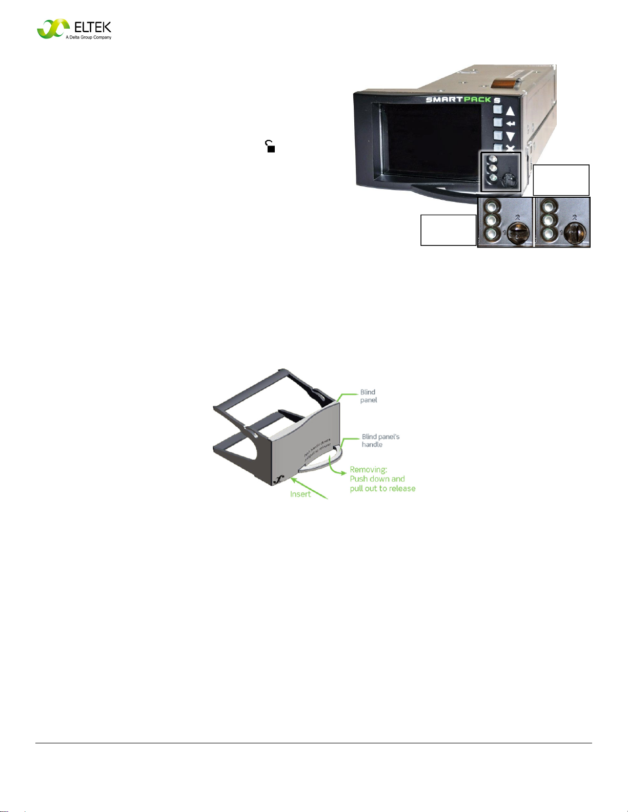
1. Ensure that rectifiers are unlocked during
installation. Using a screwdriver, turn the locking
screw to the unlocked position ( ).
Note: The rectifier can be mounted in the power
shelf with the locking screw in either locked and
unlocked positions, but the recommended practice
is to keep the rectifier unlocked during installation
and removal, until the unit is properly in place.
2. Insert each rectifier into position by sliding it fully
into the power shelf (providing support from
underneath), so that it makes proper contact.
NOTE: Ensure that line cords and AC breakers or
fuses are properly sized to accommodate the
maximum current draw of all rectifiers that are
powered by each feed.
NOTE: Make sure the load requirement does not
exceed the current rating (as labeled on the shelf),
before installing rectifiers. It is possible to exceed
the output ratings of some shelves if they are fully
populated with the Flatpack S 48V/1800W HE
rectifiers, which can output up to 36.3A of current.
Maximum weight per rectifier: 1.9 lbs. (850 g)
Unlocked
Locked
ATTACHMENT R & S
BID 15-20: 700/800 MHz EDACS and P25 COMMUNICATIONS SYSTEM
5
6
Quick Start Guide Flatpack S DC System ~ Document 370012.103, Issue 1.4, March 2016
Removing and Installing Smartpack S Controllers
The shelf is shipped with the Smartpack S controller
preinstalled. If it is necessary to remove or reinstall the
controller, note the following steps.
1. Ensure that the controller is unlocked during
removal or installation. Using a screwdriver, turn
the locking screw to the unlocked position ( ).
Note: When the mechanism is locked (position #1),
the Ethernet port can be accessed by sliding the
front section of the controller forward from within
shelf. The controller can be mounted in the power
shelf with the locking screw in either locked and
unlocked positions, but the recommended practice
is to keep the controller unlocked during installation
and removal, until the unit is properly in place.
2. Insert the controller into position by sliding it fully into the
power shelf (providing support from underneath), so that
it makes proper contact
Removing and Installing Rectifier Blind Panels
Locked
(
p
osition 1)
Unlocked
(
p
osition 2)
ATTACHMENT R & S
BID 15-20: 700/800 MHz EDACS and P25 COMMUNICATIONS SYSTEM
6

Quick Start Guide Flatpack S DC System ~ Document 370012.103, Issue 1.4, March 2016
7
Location of Terminals and Ports – Smartpack S Controller
The Smartpack S controller (P/N 242100.410) contains an Ethernet port for a network connection. There are six
alarm inputs and six output alarm relays built-in. See the diagram below for a summary of all available terminals and
ports.
Accessing the Controller's Ethernet Port
NOTE: Due to space limitations, the Ethernet cable must have a connector with no strain relief boot. Ethernet
cables without strain relief boots on either a straight connector or a 90-degree left-angle connector are available
from Eltek.
ATTACHMENT R & S
BID 15-20: 700/800 MHz EDACS and P25 COMMUNICATIONS SYSTEM
7

8Quick Start Guide Flatpack S DC System ~ Document 370012.103, Issue 1.4, March 2016
Overview: Flatpack S Shelf Specifications
Flatpack S 1U shelves are available in a variety of capacities and distribution configurations. The table below
summarizes the distinctive features of each shelf.
Table 4 – Flatpack S Shelves
Shelves System Profile Dimensions Rectifier Profile AC Input Mounting
Part Number(s) System
Voltage
Wire Feed
Direction
Dc
Distribution
Rack
Width
Shelf
Depth
Rectifier
Slots
Maximum
Output
(dc)
Ac Feed Type &
Terminal Type
Rack Mount
Options
332748
320056 (no LVBD) 48 V Side (Load)
Rear (Battery)
10 GMT Fuses
2 Plug-in CBs 19″11.6″3 80A
Individual-feed
Barrier-strip Mid only
330180
330179 (no LVBD) 48 V Rear 10 GMT Fuses
2 Plug-in CBs 19″11.6″3 80A
Individual-feed
Barrier-strip
Front
Mid
350197
350193 (no LVBD) 48 V Side (Load)
Rear (Battery)
10 GMT Fuses
2 Plug-in CBs 19″11.6″3 80A
Individual-feed
Barrier-strip Mid only
350196
350204 (no LVBD) 48 V Rear 10 GMT Fuses
2 Plug-in CBs 19″11.6″3 80A
Individual-feed
Barrier-strip
Front
Mid
350195
350200 (no LVBD) 48 V Rear 4 Plug-in CBs 19″11.6″3 80A Individual-feed
Barrier-strip
Front
Mid
NOTE: All shelves are equipped with a Smartpack S controller.
Shelf Dimensions and Minimum Clearances
The Flatpack S 1U shelves are designed with a small footprint for use in a variety of applications where space is
limited, such as outdoor cabinets. The dimensions and recommended clearances are provided below.
Dimensions (top view)
ATTACHMENT R & S
BID 15-20: 700/800 MHz EDACS and P25 COMMUNICATIONS SYSTEM
8

Quick Start Guide Flatpack S DC System ~ Document 370012.103, Issue 1.4, March 2016 9
Dimensions (side view)
Dimensions (front view)
ATTACHMENT R & S
BID 15-20: 700/800 MHz EDACS and P25 COMMUNICATIONS SYSTEM
9
10 Quick Start Guide Flatpack S DC System ~ Document 370012.103, Issue 1.4, March 2016
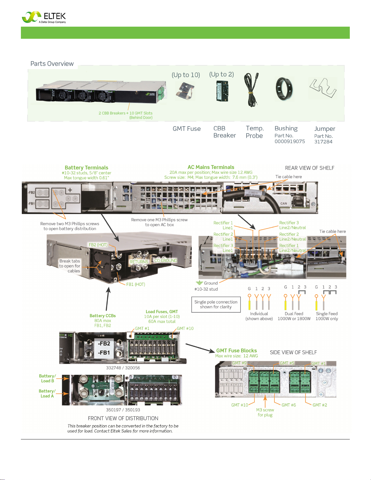
Overview: Flatpack S 48V, 3-Rectifier Shelf (332748/320056/350197/350193)
10 GMT Fuses, 2 CBB Circuit Breakers
Location of Terminals
Spacing
is needed
between
7A – 10A
loads; no
spacing is
necessary
between 6A
loads and
less.
Make ground wire longer and
connect ground first.
ATTACHMENT R & S
BID 15-20: 700/800 MHz EDACS and P25 COMMUNICATIONS SYSTEM
10

Quick Start Guide Flatpack S DC System ~ Document 370012.103, Issue 1.4, March 2016 11
Overview: Flatpack S 48V, 3-Rectifier Shelf (330180/330179/350196/350204)
10 GMT Fuses, 2 CBB Circuit Breakers
Location of Terminals
Spacing is needed between
7A–10A loads; no spacing is
necessary between 6A loads
and less.
Make ground wire longer and
connect ground first.
ATTACHMENT R & S
BID 15-20: 700/800 MHz EDACS and P25 COMMUNICATIONS SYSTEM
11

12 Quick Start Guide Flatpack S DC System ~ Document 370012.103, Issue 1.4, March 2016
Overview: Flatpack S 48V, 3-Rectifier Shelf (350195/350200)
4 CBB Circuit Breakers
Make ground wire longer and
connect ground first.
ATTACHMENT R & S
BID 15-20: 700/800 MHz EDACS and P25 COMMUNICATIONS SYSTEM
12

Quick Start Guide Flatpack S DC System ~ Document 370012.103, Issue 1.4, March 2016
13
Start Up
Before Starting the System
1. Check that all electrical connections are secure.
2. Install rectifiers (if they were not installed already).
WARNING: If connecting batteries, note that improper battery connections can cause injury or death and may
ignite a fire.
Starting the System
1. Switch on external AC Mains circuit breakers.
2. Verify AC input voltages are OK and green LED lamps are on.
3. Verify DC output voltage (Vout) is OK (for example, unplug FB1 and measure). Adjust if necessary.
4. Verify all Alarm Relays work properly.
5. Switch ON internal Battery circuit breakers. FB1 and FB2.
6. Verify Vout = FVbatt or Vload. Adjust if necessary.
7. Switch ON internal Load circuit breakers, if applicable.
8. Switch ON external Load circuit breakers.
9. Verify no alarms are displayed.
Adjusting DC Output/Battery Charging Voltage
Using the controller’s front keys:
1. Select System Configuration > Power System > System Voltage Levels > Reference Voltage.
2. Adjust the Voltage.
Alarm Relay Test
Using the controller’s front keys:
1. Select Command > Output Test.
2. Select relay to test; relay contacts will toggle for several minutes.
For system operation and monitoring information, consult the documentation listed on the front page of this guide.
Internal battery
breakers
Internal load
breakers
ATTACHMENT R & S
BID 15-20: 700/800 MHz EDACS and P25 COMMUNICATIONS SYSTEM
13
14
Quick Start Guide Flatpack S DC System ~ Document 370012.103, Issue 1.4, March 2016
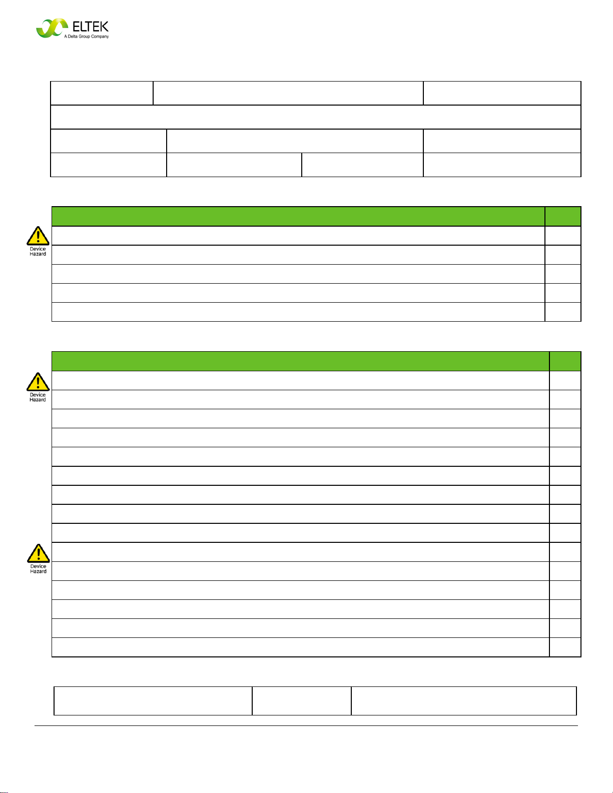
COMMISSIONING PROCEDURE
System Data Flatpack S System
System Order No. Flatpack S Power Supply System, type Article No.
Site name
Serial No. Software Version No. Rectifiers, type and number of
AC Input Voltage, measured Battery Type, if applicable Battery Capacity Commissioning carried out by, name
Pre-Start Check Power is OFF!
CHECK FOLLOWING: OK
1. Flatpack S System installation is completed
All cabling is securely terminated with correct polarity
2. All external load MCBs/circuit breakers/fuses are switched OFF
3. AC input cable(s) and AC wire (PE) are terminated
4. Site specific parameters and settings are known
5. AC supply and all external and internal MCBs/circuit breakers/fuses are switched OFF
Start-up, No-Load & Load Adjustments Power is ON!
CARRY OUT FOLLOWING: OK
1. Disconnect all rectifier modules (keep original location)
2. Switch ON the system (external AC MCBs/circuit breakers/fuses ON
3. Verify that AC input voltage is correct; then turn OFF AC power
Measure and verify
4. Connect all Flatpack S rectifiers in their original locations; then turn AC power back ON
5. The Smartpack S controller and all rectifier modules are working, LEDs are ON
Verify
6. Connect a PC to the PS system
Use a standard Ethernet cable and access the controller
7. DC output voltage
Measure and adjust
8. Alarm relay test
Verify all alarm relays are working correctly
9. System setup is in accordance with configuration
Enter site spec. info via front keys or PC)
10. Adjust DC output voltage to equal measured battery voltage
Check for correct polarity!
11. Unplug all rectifiers but one, and connect all battery fuses/CBs
12. Adjust DC output voltage to equal nominal battery or load voltage
13. Turn off AC power
14. Plug in again all rectifiers, turn on AC power, and verify the rectifiers’ current sharing
15. Verify no alarms are displayed
Approval
Responsible of commissioning, sign Date Approved by customer, sign
ATTACHMENT R & S
BID 15-20: 700/800 MHz EDACS and P25 COMMUNICATIONS SYSTEM
14

Quick Start Guide Flatpack S DC System ~ Document 370012.103, Issue 1.4, March 2016
15
MAINTENANCE PROCEDURE
System Data Flatpack S PS System
Flatpack S Power Supply System, type Article No.
Site name
Serial No. Software Version No. Rectifiers, type and number of
AC Input Voltage, measured Battery Type, if applicable Battery Capacity Commissioning carried out by, name
WARNING: Maintenance work on live equipment is only to be performed by authorized and qualified persons using
calibrated instruments of measurement and insulated tools. Hazardous voltages inside may cause terminal injury.
System Inspection Power is ON!
CARRY OUT THE FOLLOWING: OK
1. Site specific parameters and settings are known.
User manuals and site-specific connection and arrangement drawings are available.
2. The battery bank has been fully charged in advance.
At least for 12 hours since start-up or mains failure. Enables correct measurements and calibration.
3. The equipment is free from damage, dust, or dirt; verify.
Carefully vacuum clean or remove any accumulation of dust, corrosion, or dirt.
4. All cabling and copper bars are securely terminated and supported.
Correct any loose connections, excessive cable temperature, defective insulation, etc.
5. The system controllers and all rectifier modules are ON, no alarm present; verify.
Otherwise, correct and put the PS system in normal mode of operation.
6. All rectifier’s functionality and controller’s keys and display work OK; verify.
Correct possible abnormalities before continuing.
7. Connect the system’s controller to a PC
(Ethernet connection)
Access the controller from the PC’s web browser, thus enabling system configuration.
8. Rectifiers’ load current sharing; verify.
(Using the keypad on the controller or from the PC)
Check all rectifiers output the same amount of current (± 1A)
9. Display the stored log of Alarm Messages.
Using the keypad on the controller or from the PC.
System Adjustment Power is ON!
CARRY OUT THE FOLLOWING: OK
1. DC Output Voltage Calibration; ensure correct display readings.
If measured DC output voltage at the load terminals deviates more than ± 1A from the display reading, calibrate the output voltage from the
controller’s keypad or the PC.
2. Load and Battery Current Calibration; verify correct display readings.
Measure with a clip-on ammeter the battery current and every load circuit current. Calculate the total load and battery current. If the
calculated total values deviate more than ± 2% from the display readings, calibrate the current from the PC (calibration value >50% of
system’s max. capacity).
3. DC Output Voltage Adjustment; measure and adjust.
Measure and, if required, adjust the output voltage to the nominal voltage recommended by the battery manufacturer. (Voltage
measurements to be done at the DC rail, with little load current.)
4. Alarm Relay Test; verify all alarms are working correctly
From the controller’s keypad or PC use the Relay Test function; verify activation of external equipment.
5. Battery bank control; measure and verify battery specification.
Follow the recommendations of the actual battery manufacturer.
Approval
Responsible of commissioning, sign Date Approved by customer, sign
ATTACHMENT R & S
BID 15-20: 700/800 MHz EDACS and P25 COMMUNICATIONS SYSTEM
15

16 Quick Start Guide Flatpack S DC System ~ Document 370012.103, Issue 1.4, March 2016
For assistance with technical questions and solutions, please contact Technical Support
ATTACHMENT R & S
BID 15-20: 700/800 MHz EDACS and P25 COMMUNICATIONS SYSTEM
16
This manual suits for next models
8
Table of contents
Popular Power Supply manuals by other brands


Assa Abloy
Assa Abloy SECURITRON BPSM-12-6 Operation and installation instructions

OCZ
OCZ OCZ500SXS - MECHANICAL DRAWING Mechanical drawing

Solar Stik
Solar Stik G-BOSS E LIGHT Operation and maintenance manual

Monacor
Monacor PSS-600E quick guide

Fortis
Fortis SG200 user manual

Phoenix Contact
Phoenix Contact QUINT UPS-IQ quick start guide


