Novex EI8600 User manual

USER GUIDE
For Research Use Only. Not for use in diagnostic procedures.
PowerEase®500 Power Supply
A programmable power supply for electrophoresis
Catalog Numbers EI8600, EI8700, and EI8675
Document Part Number A12162
Publication Number MAN0000738
Revision 9.0


Table of Contents
Warning...................................................................................................................................................................4
Kit Contents............................................................................................................................................................5
Product Specifications...........................................................................................................................................6
Front and Rear View of PowerEase®500............................................................................................................7
Introduction..........................................................................................................................................................10
Description of PowerEase®500 ..........................................................................................................................10
Methods ....................................................................................................................... 12
Getting Started .....................................................................................................................................................12
Operational Modes ..............................................................................................................................................13
Using PowerEase®500.........................................................................................................................................14
Printing..................................................................................................................................................................21
Custom Methods..................................................................................................................................................22
Troubleshooting...................................................................................................................................................24
Appendix...................................................................................................................... 25
Instrument Symbols and Safety.........................................................................................................................25
Consignes De Securite.........................................................................................................................................26
Sicherheits Anweisungen ...................................................................................................................................27
Run Conditions for Gels .....................................................................................................................................28
Repair, Maintenance, and Cleaning ..................................................................................................................29
Background Information on Voltage, Current, and Resistance.....................................................................31
Accessory Products..............................................................................................................................................32
Technical Support ................................................................................................................................................33
3

Warning
Federal
Communications
Commission
Advisory
This equipment has been tested and found to compl
y
with the limits for a Class
A digital device, pursuant to part 15 of the FCC rules. These limits are designed
to provide reasonable protection against harmful interference when the
equipment is operated in a commercial environment. This equipment
generates, uses, and can radiate radio frequency energy and, if not installed and
used in accordance with the instruction manual, may cause harmful
interference to radio communications. Operation of this equipment in a
residential area is likely to cause harmful interference in which case the user
will be required to correct the interference at their expense.
Changes or modifications not expressly approved by the party responsible for
compliance could void the user’s authority to operate the equipment.
4

Kit Contents
Types of Kits This manual is supplied with the followin
g
kits:
Kit Catalog No.
PowerEase®500 Power Supply (100/120 Vac 50/60 Hz) EI8600
PowerEase®500 Power Supply (220/240 Vac 50/60 Hz) EI8700
PowerEase®500 Pre-Cast Gel System
includes PowerEase®500, Temperature Monitoring Probe,
XCell
SureLock
™Mini-Cell and XCell II™Blot Module
EI8675
Kit Components PowerEase®500 Power Suppl
y
contains:
PowerEase®500 Power Supply 1 each
Instruction Manual 1 each
Extra Fuses 2 each
Power Cord (U.S., Canada, Europe, Taiwan and Japan) 1 each
Warranty Card 1 each
Temperature Probe (Optional) 1 each
See page 6for specifications and detailed description of PowerEase®500 Power
Supply.
Note To ensure safe, reliable operation, alwa
y
s operate the PowerEase®500 Power
Supply in accordance with the manufacturer’s instructions. Always wear
protective gloves and safety glasses when working in a laboratory environment.
See safety information on pages 25–27.
Warranty information is provided on page 33.
5

Product Specifications
Specifications Input Powe
r
100–120 VAC: 100–120V, 50/60 Hz, 1.2 A at maximum load
Fuse: One 1A/250V/AGC fast blow fuse
220–240 VAC: 220–240VAC, 50/60 Hz, 0.5 A at maximum load
Fuses: Two 1A/250V/5 × 20 mm fast blow fuses
Output Range 1–500 V (minimum step size 1 V)
1–500 mA (minimum step size 1 mA)
0.1–50 W (minimum step size 0.1 W)
Automatic crossover on reaching set limits.
Accuracy Voltage: ± 2% or ± 2 volts
Current: ± 2% or ± 2 mA
Wattage ± 2% or ± 0.2 watt
Drift < 1% in 8 hours after 30 minute warm-up
with constant supply voltage
Circuit Protection Open Circuit; Short Circuit; Thermal Protection
Over Voltage, Current, Wattage
Safety Load Detection
Thermal Shutoff (with optional temperature probe)
Isolated Floating Ground
Memory Control Non-volatile, up to 24 hours
Custom Methods Stored to RAM
Computer Interface RS232C
Display LCD, view area 114 x 64 mm
240 × 128 dots
Dimensions 16.5 cm (w) × 18 cm (h) × 20.5 cm (d)
Weight 2.9 kg (6.4 lbs)
Operating Ambient temperature 4–30°C, ≤80% relative
Environmental humidity, altitude < 2000 meters, indoor use only,
Conditions pollution degree 2
6
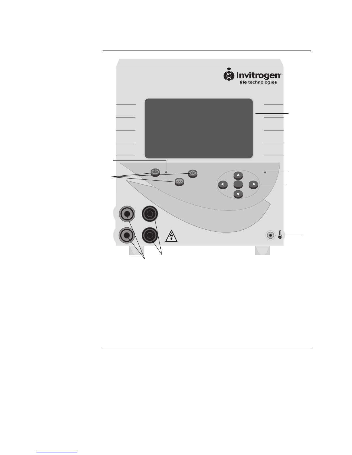
Front and Rear View of PowerEase®500
Front View of
PowerEase®500
+
TEMP
P
o
w
e
r
E
a
s
e
5
0
0
SELECT
S
T
O
P
S
T
A
R
T
POWER HIGH VOLTAGE
1
7
4
3
5
2
6
8
1. LCD Screen
2. Power Output Jacks, Positive (Red)
3. Power Output Jacks, Negative (Black)
4. Temperature Probe Jack
5. Functional Keys (Power, Start, Stop)
6. Directional Keys (Up, Down, Left, Right)
7. High Voltage LED
8. Power LED
Continued on next page
7
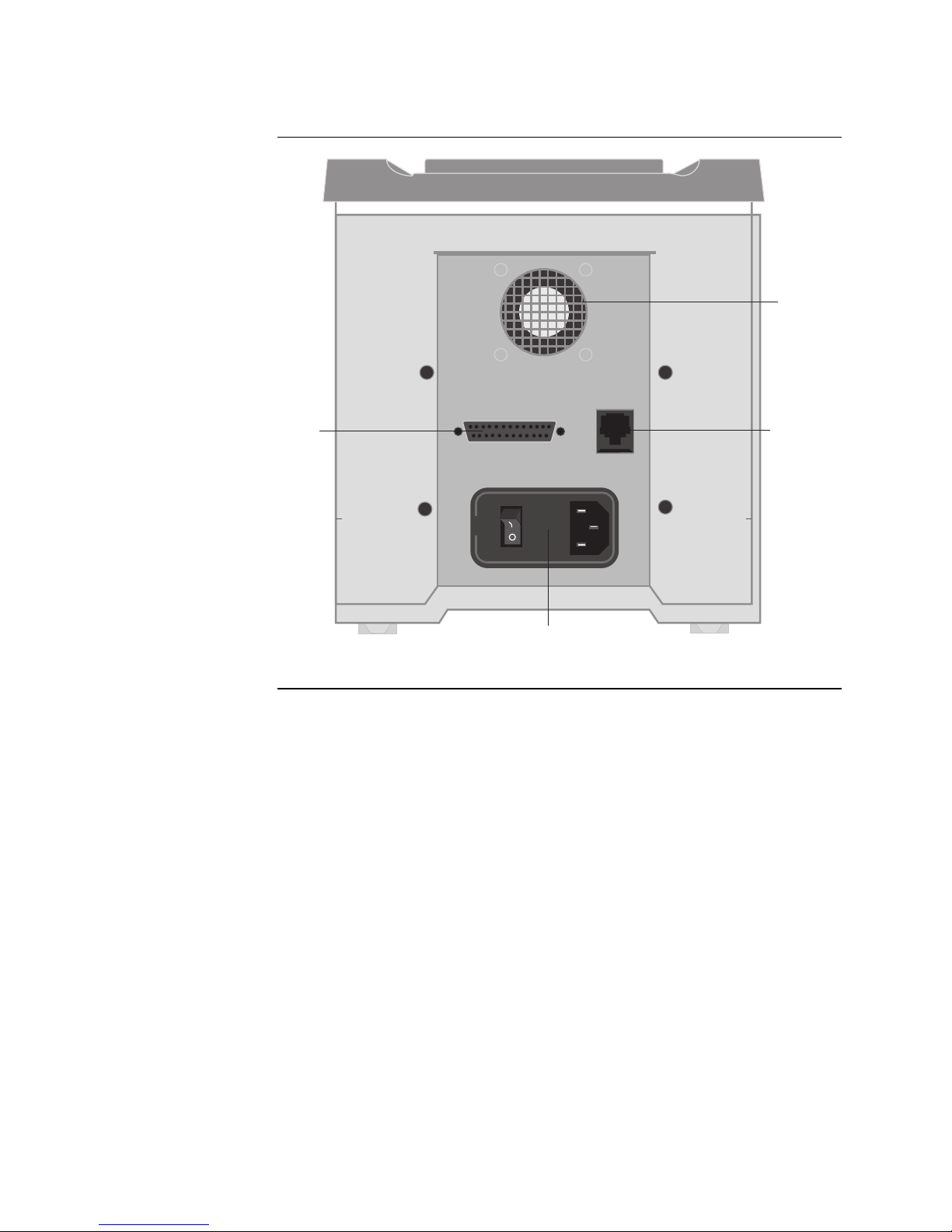
Front and Rear View of PowerEase®500, Continued
Rear View of
PowerEase®500
PRI TER
RS232
Fan
RS232C
Communi-
cation
Port
Printer
Port
Power Entry Module
with On/Off
main power switch
Continued on next page
8
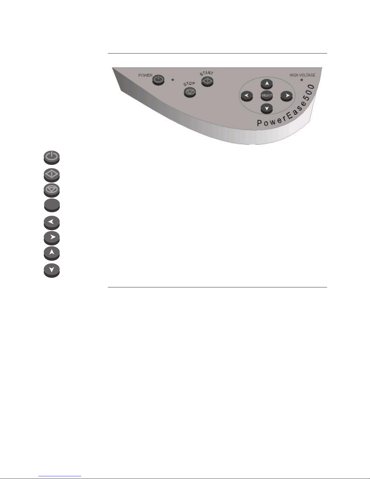
Front and Rear View of PowerEase®500, Continued
Key Pad
Power button secondary On/Off switch for the high voltage components, fan, and LCD
screen.
Start button used to start a selected method program.
Stop button used to end the selected method and to backup to a previous screen.
SELECT
Select button used to select a menu choice and to move forward to the next applicable
screen.
Left directional button for moving left around the menu.
Right directional button for moving right around the menu.
Up directional button for moving up around the menu and to adjust numerical and
character values (higher).
Down direction button for moving down around the menu and to adjust numerical and
character values (lower).
9

Introduction
Description of PowerEase®500
Product
Description
The PowerEase®500 Power Suppl
y
is a microprocessor-controlled power suppl
y
for electrophoresis of pre-cast and hand-poured mini-gels. The power supply is
designed to simplify electrophoresis by combining high performance and
programming flexibility with ease of use when running mini-gel and blotting
applications.
The PowerEase®500 Power Supply is designed around the single gel concept:
you need to think only about the electrical parameters and limits for a single gel.
This manual describes the setup and operation of PowerEase®500 Power Supply
including important information on safety and maintaining the unit.
Features of
PowerEase®500
The important features of PowerEase®500 Power Suppl
y
are:
•Large LCD display allows electrical parameters to be displayed in either
graphical or numerical formats
•Eight pre-programmed methods for running and blotting Novex®pre-cast
mini-gels
•Four custom methods for running your custom applications
•Simple three step operating procedure to start running or blotting Novex®
pre-cast gels
•Microprocessor control provides highly accurate electrical outputs resulting
in exceptional blotting capability
•Parallel port for printing experimental results to most printers
•Optional Temperature Probe to continuously monitor the buffer temperature
and shut the unit down in the event of overheating
•Two sets of output jacks allows electrophoresis of multiple mini-cell units in
constant voltage, current, or watts
Continued on next page
10

Description of PowerEase®500, Continued
Flowchart The followin
g
flowchart describes the various screens displa
y
ed on the
PowerEase®500 Power Supply and the keypad buttons (Start, Stop or Select)
used to navigate through the screens.
Start/Select
Start
Select
Power ON
Start-Up Screen
Gel Method Screen
Gel Quantity Screen
Method Run Large Display
Stop
Select
Method dit Screen Method Run Large Display Previous Screen
StopStart
Previous Screen
Select, once Select, twice
Select Method Run/ dit Screen
Method Run Graphic Display
Select, onceSelect, twice
Method Run Large Display
Method Run Graphic Display
11

Methods
Getting Started
Installing
PowerEase®500
1. Place the PowerEase®500 Power Suppl
y
on a level bench. Keep the area
around the power supply clear to ensure proper ventilation of the unit.
2. Position the unit properly such that the On-Off switch and the power cord
attachment module located on the rear of the unit are easily accessible.
3. Check the label located near the power entry module to ensure that the unit
is of the proper local voltage. Attach the power cord to the power entry
module. Use only properly grounded AC outlets.
Installing an
Optional Printer
The PowerEase®500 Power Suppl
y
has a DB25 parallel connector located on the
rear of the unit. This allows the PowerEase®500 Power Supply to print a report
of your electrophoresis results in ASCII format to most commonly available
printers.
Use the following steps to install a printer:
1. Using a parallel printer cable, connect the male DB25 end of the printer cable
into the port marked “Printer” located on the rear of the PowerEase®500
Power Supply.
2. Connect the opposite end of the cable into the appropriate connector on the
printer. Refer the user manual of your printer for instructions on connecting
the cable to the printer.
RS232 Port The RS232 Port is desi
g
ned to be connected to a computer durin
g
dia
g
nostics
and/or servicing by qualified field service engineers only.
Installing an
Optional
Temperature
Probe
If
y
ou have ordered the Temperature Monitorin
g
Probe, use the followin
g
instructions to install the probe:
1. Unpack the Temperature Monitoring Probe and inspect for any possible
damage to the wire or connector which may have occurred during shipping.
2. Plug the connector end of the Temperature Monitoring Probe into the port
located at the front lower right corner of the PowerEase®500 Power Supply
marked “TEMP”.
3. Place the opposite end of the Temperature Monitoring Probe with the blue-
colored bead into an electrophoresis cell buffer chamber to display
temperature on the LCD screen of the PowerEase®500 Power Supply. You
can bent the wire, but avoid crimping or pinching the wire. Temperature will
be displayed at all times even when the PowerEase®500 Power Supply is
stopped.
12

Operational Modes
Introduction The PowerEase®500 Power Suppl
y
is capable of operatin
g
at limitin
g
volta
g
e,
limiting current, and limiting power. We recommend operating the PowerEase®
500 Power Supply at limiting voltage for most applications. See below for more
details.
Voltage Limiting
The recommended settin
g
for operatin
g
the PowerEase®500 Power Suppl
y
is
voltage limited. For most electrophoresis methods, resistance increases
throughout the run. Using voltage limiting provides the following advantages:
•Current and watts decrease throughout the run, providing a natural safety
margin.
•The same voltage setting can be used regardless of the number or thickness
of gels being electrophoresed.
Current Limiting Discontinuous buffer s
y
stems and, to a lesser extent continuous s
y
stems,
increase resistance during the run. If you use the current limiting setting on the
PowerEase®500 Power Supply, the voltage will increase as resistance increases
to satisfy Ohm’s law (V=IR, see page 21). If no voltage limit is set and a local
fault condition occurs, such as a poor connection, very high local resistance
may cause the voltage to increase to a maximum of the power supply. This will
lead to local overheating and damage to the electrophoresis cell or create unsafe
conditions.
When running under constant current conditions, set a voltage limit on the
power supply at or slightly above the maximum expected voltage.
Wattage Limiting If power is constant, volta
g
e will increase and current will decrease durin
g
a
run, but the total amount of heat generated by the system will remain constant
throughout the run. However, locally high resistance can cause a high
proportion of the total heat to be generated over a small distance. This can
damage the electrophoresis cell and/or gel(s).
If operating at wattage limiting, set the voltage limiting to slightly above the
maximum expected for the run.
13

Using PowerEase®500
Introduction You can operate the PowerEase®500 Power Suppl
y
immediatel
y
after
installation using three simple steps (see below). For programming custom
settings, see page 22.
Starting
PowerEase®500
1. Plu
g
the power cord of the PowerEase®500 Power Suppl
y
into an available
electrical outlet rated at the appropriate electrical values for the power
supply.
2. Turn on the main power switch located on the rear of the PowerEase®500
Power Supply (see page 8for rear view of PowerEase®500 Power Supply).
Always leave this switch in the ON position to keep the back-up battery fully
charged.
3. Press the Power button located on the keypad (see page x for a figure of the
keypad). This Power button is a secondary power button and does not
actually shut the instrument down, but shuts down the high voltage, fan,
and LCD screen. When powered back up, the LCD screen will revert to the
same screen as when the secondary power was shut off.
4. A Start-Up screen appears (see page 15).
To avoid condensation, the main power switch located on the rear of the unit
should be left on between use during operation in a cold room or in high
humidity environments.
Operating
PowerEase®500
A simple operatin
g
procedure of the PowerEase®500 Power Suppl
y
is provided
below. For more details on the different screens and custom methods, see
pages 14–23.
1. Turn on the PowerEase®500 Power Supply.
2. Press Select once the Start-Up screen appears.
3. Select your gel type from the Gel Method screen.
4. Choose the number of gels to be electrophoresed from the Gel Quantity
screen.
5. Press the Start button to begin electrophoresis.
Note: To reset the PowerEase®500 Power Supply, press the Stop button.
Note The maximum number of Novex®mini-
g
els that can be electrophoresed at the
same time using PowerEase®500 Power Supply and the XCell SureLock™Mini-
Cell is listed in the following table:
Gel Type Number of Gels
Novex®Tris-Glycine Gels 10 gels
NuPAGE®Novex®Tris-Acetate Gel 6 gels
NuPAGE®Novex®Bis-Tris Gels 2 gels
Novex®Tricine Gels 4 gels
Novex®TBE-Urea gels 10 gels
Continued on next page
14

Using PowerEase®500, Continued
Start-Up Screen The Start-Up screen is the first screen to appear after pressin
g
the Power
b
utton
on the keypad.
Press the Select button to advance to the Gel Method screen.
Note: After first use, the last screen previously in use will appear after shutting
the power off and back on again.
Gel Method
Screen
The Gel Method screen (see fi
g
ure below) allows
y
ou to select from a choice of
eight pre-programmed methods for Novex®mini-gels or four user-defined
methods.
1. Use the directional arrow buttons to navigate through the menu.
2. Press the Select button to choose the method. You will advance to the Gel
Quantity screen (see next page) if a pre-programmed method is chosen, or to
the Custom Method Option screen (see page 22) if a user defined method is
selected.
Note: The pre-programmed method durations are set to the shortest run time per
gel type, or buffer level and buffer strength to prevent over-running a gel.
Different percentage gels within a single gel type can cause a gel to take longer to
run. Additional time can be added to the pre-programmed method before,
during, and after a run (see page 20).
TBE Gel
Tris-Gly Gel
User-Custom3
User-Custom1
Western Blot
IEF Gel
uPAGE Blot
uPAGE Gel
TBE-Urea Gel
Tricine Gel
User-Custom2
User-Custom4
SELECT to continue
and moves cursor
Continued on next page
15

Using PowerEase®500, Continued
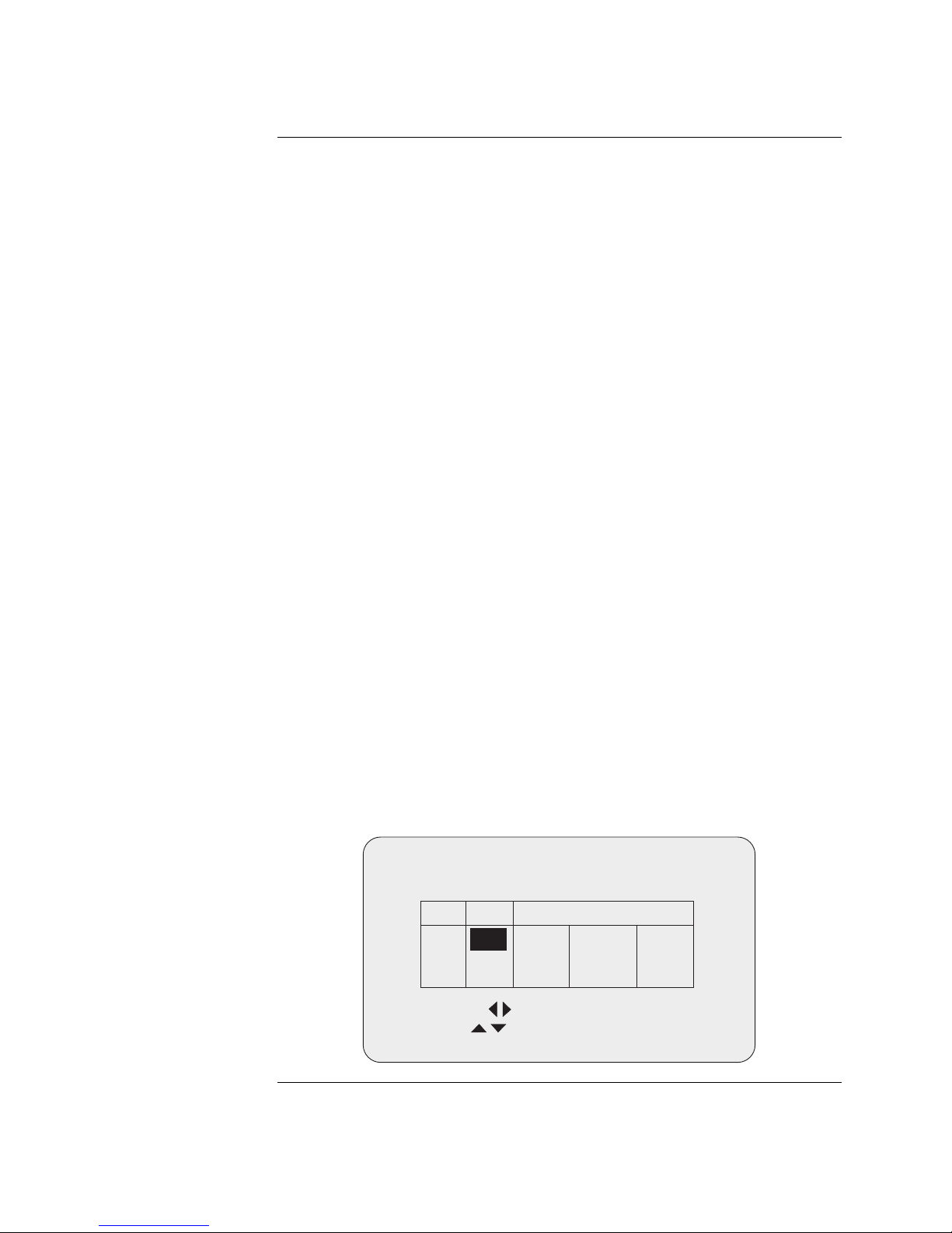
Gel Quantity
Screen
The Gel Quantit
y
screen (see the followin
g
fi
g
ure) allows
y
ou to scale the pre-
programmed method’s current and power values by the number of gels that are
to be run.
1. Use the Up and Down arrows on the keypad to increase or decrease the
number of gels from 1 to the maximum allowable quantity of gels which can
be run for the specified method.
2. Press the Start button to begin the electrophoresis. The Method Run Large
Display screen will be displayed.
3. If you need to edit any electrophoresis parameters, press the Select button to
advance to the Method Edit screen (see page 19).
The Stop button returns you to the Gel Method screen (or the Custom Method
Options screen if a custom method is in use).
If the number of gels selected causes the current to be scaled such that the
PowerEase®500 Power Supply maximum power limit of 50 watts is exceeded, an
error message “Power Limit Reached” will be displayed. Similarly, if the current
exceeds 500 mA, an error message “Current Limit Reached” will be displayed.
Change the number of gels appropriately to continue electrophoresis.
Note: Avoid changing the number of gels during the run, unless gels are
removed during the run. If you would prefer to see the total output parameters,
leave the gel number at “1” before starting.
Tris-Glycine Gel
umber of
Gels to be run:
START begins; SELECT edits
adjust number of gels
2
Continued on next page
16

Using PowerEase®500, Continued
Method Run Large
Display
The Method Run Lar
g
e Displa
y
screen (see the followin
g
fi
g
ure) is displa
y
ed
after the Start button is pressed from the Gel Quantity screen or the Method
Edit screen. This screen displays the status of the method during a run in an
easy to read format. The screen displays:
•Selected Method
•Status (running or paused)
•Number of Gels
•Run Condition (Limiting Parameters)
•Actual Voltage and Current (large display)
•Step Time Remaining
•Present Step Number
•Actual Wattage (small display)
•Detected Temperature (if installed)
Pressing the Select button once takes you to the Method Run Graphic Display
screen (see page 18) and to the Method Run/Edit screen (see page 19) if pressed
twice.
The Stop button pauses the run if pressed once, stops the method if the method
is already in the paused state and takes you to the Method Edit screen.
To resume, press the Start button.
Tris-Glycine Gel
Voltage is constant
RU I G
SELECT views; STOP pauses
Time
Temp:
Power:
Step:
Left: 0:07
24oC
2W
1
125V
30mA
Gels
2
Continued on next page
17
Using PowerEase®500, Continued
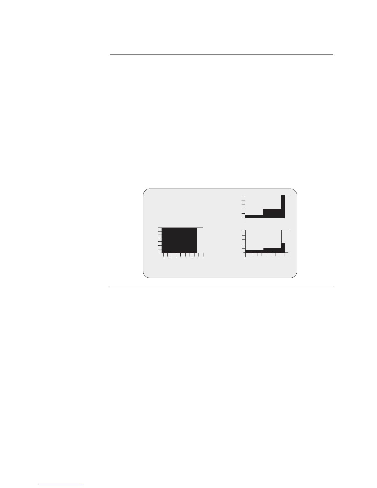
Method Run
Graphic Display
The Method Run Graphic Displa
y
screen (see the followin
g
fi
g
ure) is
displayed after the Select button is pressed from the Method Run Large
Display screen. This screen displays the status of the method during a run in a
graphical format. The screen displays:
•Selected Method
•Status (running or paused)
•Present Run Time
•Voltage, Current, and Wattage (applied during the run)
•Run Condition (Limiting Parameter)
The Select button takes you to the Method Run/Edit screen (see page 19).
The Stop button pauses the run if pressed once, stops the method if pressed
twice and takes you to the Method Edit screen.
To resume, press the Start button.
IEF Gel
500V
RU I G
SELECT views; STOP pauses
6mA
2:07
2W
c
u
r
r
e
n
t
v
o
l
t
s
p
o
w
e
r
Continued on next page
18
Using PowerEase®500, Continued
Method Edit
Screen
The Method Edit screen (see the followin
g
fi
g
ure) is displa
y
ed after the Select
button is pressed from the Gel Quantity screen. The Method Edit screen allows
you to edit the following method parameters:
•Step Duration
The maximum step duration is 24 hours. If the duration is set to zero, the
step will be deleted and all following steps will be moved up. If you set an
empty step to non-zero, the voltage, current, and wattage settings from the
previous line will be copied.
•Step Voltage Limit
•Step Current Limit
•Step Power Limit
•Load Check State
The Load Check state is either ON or OFF, and determines whether or not
the PowerEase®500 Power Supply unit will detect ‘No Load’ conditions. The
default value for Load Check is ON and is the recommended state.
•Gel Quantity
The gel quantity limit determines the maximum voltage, current, and
wattage for the step. Values must be in the range of 1–500 volts, 1–500 mA,
and 0.1–50 watts for one gel (the values for current and watts will be reduced
if multiple gels are selected).
If you have changed a pre-programmed method, the method will always run as
edited until you cycle back to the Gel Method screen. At this point the pre-
programmed method will revert to the default parameters.
To edit the parameters on this screen:
1. Press the Left or Right arrow buttons to move the cursor between different
fields. As the cursor moves from field to field, a status message on LCD
display is updated to show the affected parameters if changes are made.
2. Use the Up and Down buttons to adjust field values.
3. Press the Start button to begin the run and change the display to the monitor
state. The Stop button takes you to the Gel Quantity screen (see page 16).
Tris-Glycine Gel
START begins; STOP for prior
moves cursor
adjusts run time
Load Check: ON
24
o
C
Step Time Limits
125V 100 mA 18.0W
1
2
3
1:30
Continued on next page
19

Using PowerEase®500, Continued
Method Run/Edit
Screen
The Method Run/Edit screen (see the followin
g
fi
g
ure) is displa
y
ed after the
Select button is pressed from the Method Run Large Display screen or the
Method Run Graphic Display screen. This screen displays the status of the
method during a run and allows you to edit parameters during the run for the
current step displayed on this screen.
The screen displays:
•Selected Method
•Status (running or paused)
•Number of Gels
•Total Time Elapsed
•Run Condition (limiting parameter or error condition if detected)
•Detected Temperature (if probe is installed)
•Present Step Number
•Present Parameter Set Points
•Step Time Elapsed
•Actual Voltage, Current and Wattage
Make the appropriate change using the directional arrow keys and press the
Start button.
The Select button takes you to the Method Run Large Display if pressed once,
and to the graphic display if pressed twice.
The Stop button pauses the run if pressed once and stops the method if the
method is already paused.
20
This manual suits for next models
5
Table of contents


