Delta Tau 4Ax-603397-xUxx User manual

^1 USER MANUAL
^2 3U DIGITAL PWM AMPLIFIER
^3 3U Digital PWM Amplifier
^4 4Ax-603397-xUxx
^5 January 28, 2003
Single Source Machine Control Power // Flexibility // Ease of Use
21314 Lassen Street Chatsworth, CA 91311 // Tel. (818) 998-2095 Fax. (818) 998-7807 // www.deltatau.com

Copyright Information
© 2003 Delta Tau Data Systems, Inc. All rights reserved.
This document is furnished for the customers of Delta Tau Data Systems, Inc. Other uses are
unauthorized without written permission of Delta Tau Data Systems, Inc. Information contained
in this manual may be updated from time-to-time due to product improvements, etc., and may not
conform in every respect to former issues.
To report errors or inconsistencies, call or email:
Delta Tau Data Systems, Inc. Technical Support
Phone: (818) 717-5656
Fax: (818) 998-7807
Email: [email protected]
Website: http://www.deltatau.com
Operating Conditions
All Delta Tau Data Systems, Inc. motion controller products, accessories, and amplifiers contain
static sensitive components that can be damaged by incorrect handling. When installing or
handling Delta Tau Data Systems, Inc. products, avoid contact with highly insulated materials.
Only qualified personnel should be allowed to handle this equipment.
In the case of industrial applications, we expect our products to be protected from hazardous or
conductive materials and/or environments that could cause harm to the controller by damaging
components or causing electrical shorts. When our products are used in an industrial
environment, install them into an industrial electrical cabinet or industrial PC to protect them
from excessive or corrosive moisture, abnormal ambient temperatures, and conductive
materials. If Delta Tau Data Systems, Inc. products are exposed to hazardous or conductive
materials and/or environments, we cannot guarantee their operation.

3U Digital PWM Amplifier User Manual
Table of Contents i
Table of Contents
INTRODUCTION.......................................................................................................................................................1
Theory of Operation..................................................................................................................................................1
Power Supply Considerations ...................................................................................................................................1
Specifications............................................................................................................................................................2
Power Stage..........................................................................................................................................................2
Environmental ......................................................................................................................................................2
3U Power Supply..................................................................................................................................................2
Amplifier Display Codes...........................................................................................................................................2
CONNECTIONS .........................................................................................................................................................3
3U Amplifier Faceplate Connections........................................................................................................................3
Power Supply Faceplate............................................................................................................................................4
Hardware Connections to the Assembly ...................................................................................................................4
Hardware Connections to the Assembly ...................................................................................................................5
Power-DC Bus......................................................................................................................................................5
Power-AC Input....................................................................................................................................................6
Amplifier Power Section Pinout (603391-10x).....................................................................................................7
3U Power Supply Layout......................................................................................................................................8
3U AMPLIFIER BACKPLANE BOARD (603435-10X) .........................................................................................9
Front Side Connectors..........................................................................................................................................9
Back Side Connectors.........................................................................................................................................10
3U Amplifier Backplane Layout (Back)..............................................................................................................11
3U Amplifier Backplane Layout (Front).............................................................................................................11
TROUBLESHOOTING............................................................................................................................................13
USEFUL NOTES.......................................................................................................................................................15

3U Digital PWM Amplifier User Manual
ii Table of Contents

3U Digital PWM Amplifier User Manual
Introduction 1
INTRODUCTION
The 3U Digital PWM Amplifier board is a 3U-size amplifier designed to drive AC Induction, Permanent
Magnet Brushless, DC Brushed type motors. This amplifier unit comes in two packages: Two 680W
continuous power amplifiers or one 1360W continuous power amplifier. The 3U Digital PWM Amplifier
may be interfaced conveniently to the PMAC controller via ACC-24E2 or ACC-8F.
Typically, the amplifier is purchased with the Delta Tau 3U power supply and backplane interface card to
distribute the power to the unit.
Part Number Description
603428-10x 170V Power Supply for 3U Amplifiers
603435-10x Backplane Assembly for 3U Amplifiers
Theory of Operation
The 3U Digital PWM Amplifier is a 3-phase direct PWM drive, utilizing the latest in smart power
technology from the world’s leading vendors and the cutting edge algorithms of the PMAC2/UMAC
controller family. The 3U Digital PWM Amplifier can drive all of the motor types commonly used in
programmable motion control in both rotary and linear forms.
The 3U Digital PWM Amplifier is based on PWM (Pulse Width Modulation), a technique employing
both frequency and phase to approximate sinusoidal currents and to control AC and DC motors.
Each axis of the 3U Digital PWM Amplifier uses a three H-bridge legs scheme. Each leg employs a top
and bottom IGBT transistor. The motor windings are connected between the center points of top and
bottom pairs. When two appropriate IGBT transistors in the bridge are turned on, the current flows
through any two motor windings. Any two (top and bottom) bridge transistors are turned on by a logic
from PMAC2 with no other conditioning necessary, except an optical isolation. The 3U Digital PWM
Amplifier performs no control functions itself; it simply accepts direct PWM commands from the
PMAC2. PMAC2 requires the position feedback and the feedback about the current fed to the motors to
commutate each controlled axis.
The current feedback is provided in digital form as a part of a serial data stream of 18 bits (12 bits report
the current feedback and remaining 6 bits report fault conditions) from the current feedback A/D
converters which are located in the 3U Digital PWM Amplifier. Each axis has its own “mask” word that
tells the PMAC2 how many bits to expect from the A/D converter. The clock and the strobe for the digital
feedback are programmable at the PMAC2.
The position feedback is generally fed to PMAC2/UMAC via ACC 8F or ACC-24E2. The position
feedback is not connected to the Quad Amp in any way.
Power Supply Considerations
The 3U Digital PWM Amplifier requires a single power supply of +50V to +170V max. The current
requirement can vary depending on the load, but should not exceed 8A (4A per channel) continuous and
16A peak (8A per channel) for a 1-second period.
The logic power for the amplifier is derived from the BUS voltage. Typically, the BUS voltage can be
brought in from the amplifier backplane assembly card.
Any shunt resistors connected to the amplifiers are connected to the amplifier backplane assembly.

3U Digital PWM Amplifier User Manual
2 Introduction
Specifications
Power Stage
Description Specification
BUS Voltage (standard unit) 60V DC minimum
170V DC maximum
Max Continuous Current (per amp) 4A (RMS)
Peak Current (per amp) 8A
Maximum PWM Frequency 15 KHz
MAX ADC Current Loop Feedback 12A
Environmental
Description Specification
Operating Temperature 0°C to 55°C (32°F to 135°F)
Storage Temperature -12°C to 82°C (10°F to 180°F)
Humidity 0% to 95%, Non-Condensing
3U Power Supply
Description Specification
Main AC Input Voltage 120V AC
Frequency 50/60 Hz
Main BUS Voltage 170V
Amplifier Display Codes
The amplifier is protected against severe electrical and temperature conditions. See the table below for a
code, and explanation.
Code Description
0 Everything is OK
1 2 sec over current, axis #1
2 Short circuit, axis # 1
3 Motor over temperature fault, axis #1
4 2 sec over current, axis # 2
5 Short circuit, axis #2
6 Motor over temperature fault, axis #2
8 Under voltage, global
9 High PWM fault, global
C Over voltage, global
3U Digital PWM Amplifier User Manual
Connections 3
CONNECTIONS
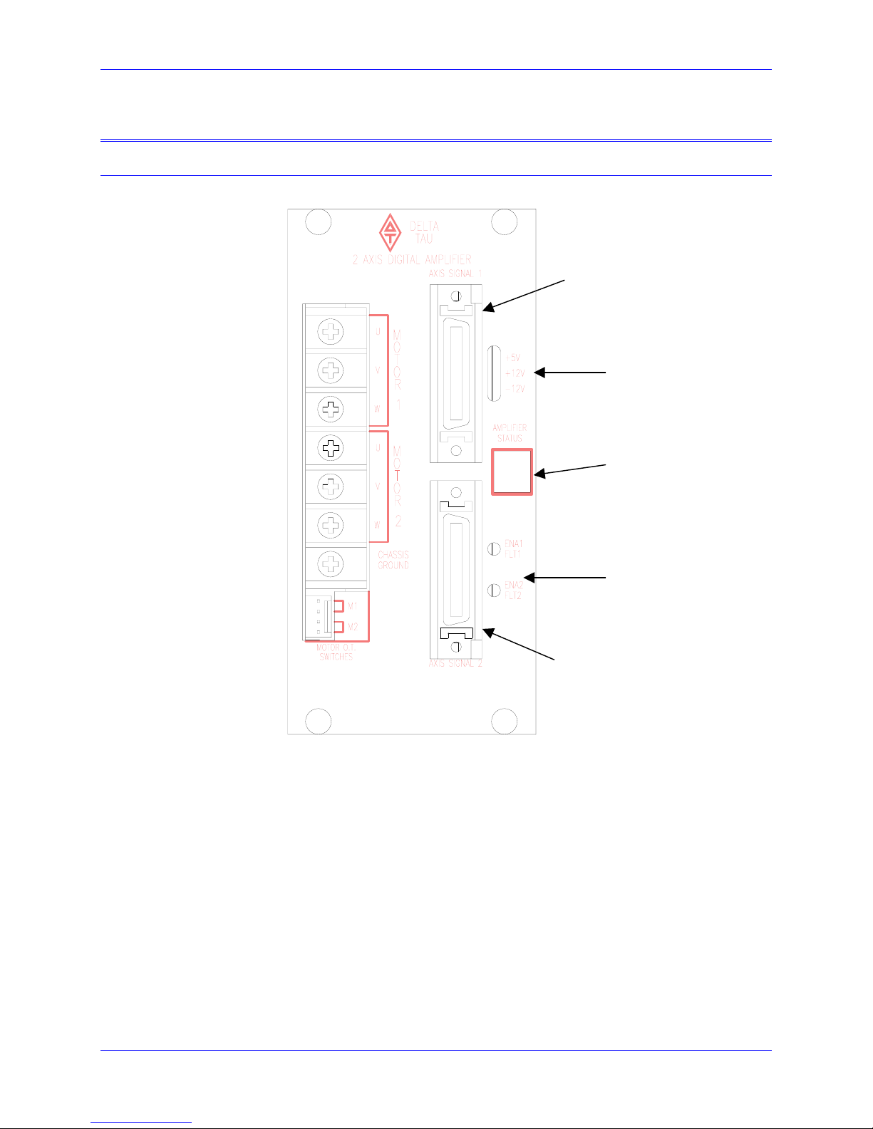
3U Amplifier Faceplate Connections
Logic Power Indicator
Amplifier Status LED
Ampliier Fault
Amplifier 1 Input/Output
Amplifier 2 Input/Output
3U Digital PWM Amplifier User Manual
4 Connections
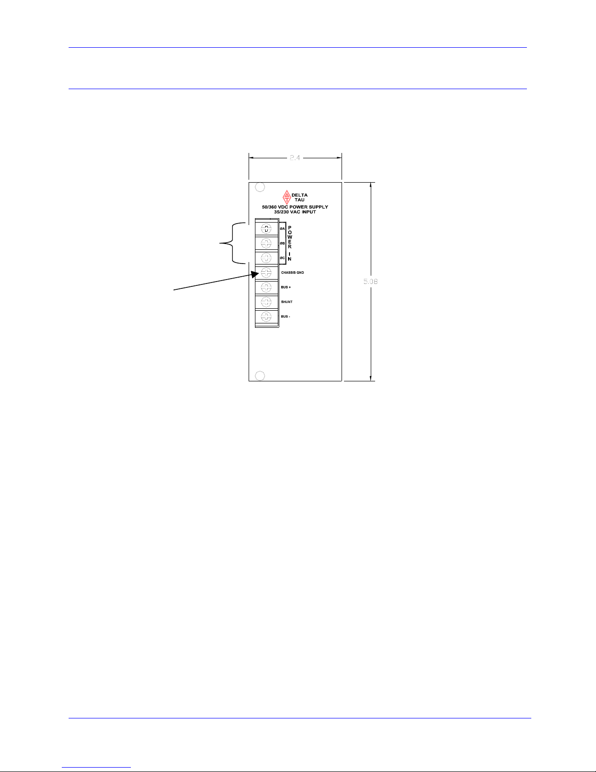
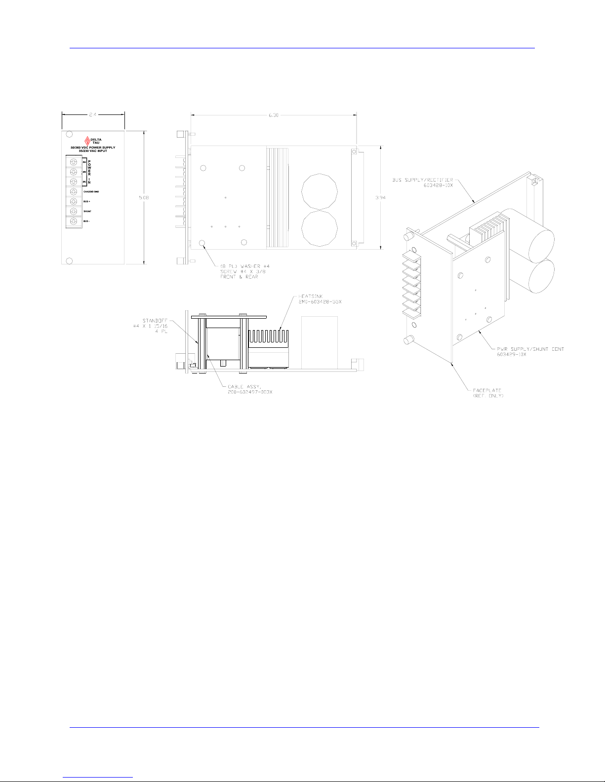
Power Supply Faceplate
MAIN AC
INPUT VOLTAGE
CHASIS
GROUND

3U Digital PWM Amplifier User Manual
Connections 5
Hardware Connections to the Assembly
Power-DC Bus
The amplifier requires an external DC bus supply. The bus can be supplied via Delta Tau Power Supply
(part of the UMAC line product), or via customer provided DC source. Such a source can be connected to
the UMAC PWM backplane, or directly to the J1 connector of the 3U power board via quick-disconnect
terminals.
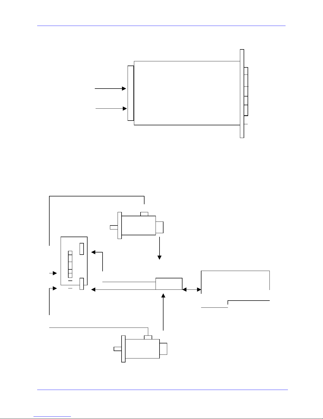
The graphic below shows two 3U PWM amplifiers and a Delta Tau Power Supply in a rack. The DC bus
is distributed through the backplane.
3U 3U Power Supply
AC line input
Chassis ground
Below are shown three 3U PWM amplifiers and a Delta Tau Power Supply in a rack. The DC bus must be
connected to the backplane.
3U 3U 3U
BUSIN+
BUSIN-
3U Digital PWM Amplifier User Manual
6 Connections
The DC bus can be connected to a stand-alone 3U amplifier via quick-disconnect terminals as shown:
BUS IN+ (pin 4)
BUS IN – (pin 6)
Power-AC Input
AC input voltage is applied to the power supply assembly ONLY. The power supply accepts three-phase
or single-phase AC voltage. For a single-phase operation, connect AC line and Neutral to any of the AC
inputs (A, B, C), and connect AC ground to Chassis GND terminal.
Typical 3U wiring diagram
Motor#1
3U
PMAC2controller
Acc8F
Acc 8F
Motor#2
3U Digital PWM Amplifier User Manual
Connections 7
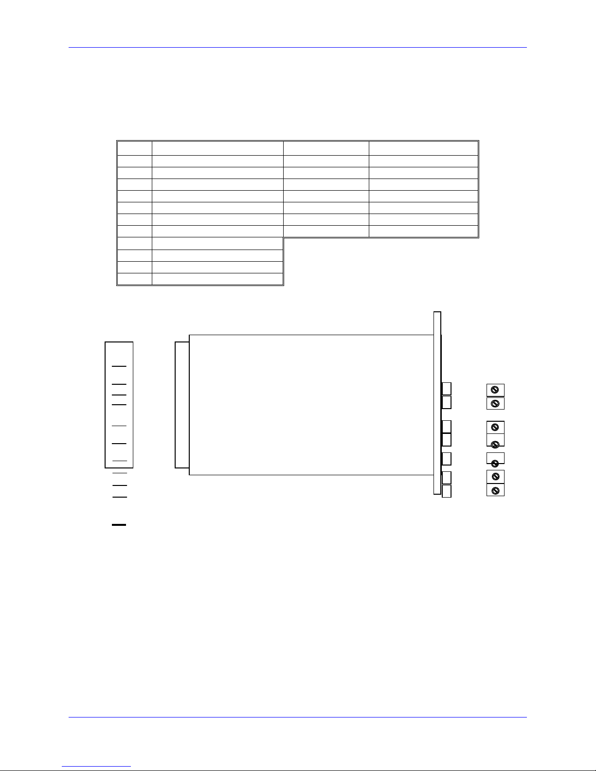
Amplifier Power Section Pinout (603391-10x)
J1 connector pin out J2 connector pin out
Pin # Description Pin # Description
1 Motor ground 1 Axis #1 W phase
2 Axis #1 W phase 2 Axis #1 V phase
3 Axis #2 W phase 3 Axis #1 U phase
4 Bus + 4 Axis #2 W phase
5 Shunt 5 Axis #2 V phase
6 Bus - 6 Axis #2 U phase
7 Bus + 7 Motor ground
8 Axis #1 V phase
9 Axis #2 V phase
10 Axis #1 U phase
11 Axis #2 U phase
pin 1
603391-10x J2 connector pin out
J1 J2
pin 11
3U Digital PWM Amplifier User Manual
8 Connections
3U Power Supply Layout
3U Digital PWM Amplifier User Manual
3U Amplifier Backplane Board (603435-10x) 9
3U AMPLIFIER BACKPLANE BOARD (603435-10X)
The 3U Amplifier Backplane Board allows plugging the 3U digital PWM amplifiers into an assembly that
distributes the BUS power for up to three 2-Axis 3U digital amplifiers. If the optional 170V power supply
is used in the system, you could plug two 2-axis 3U digital amplifiers into the Amplifier Backplane Board
Assembly. Any external shunts for the amplifier will be connected to the lug type connectors located on
the backside of the assembly. Typically, this assembly would be placed into a 3U Rack provided by Delta
Tau.
The backside of the assembly allows you to –
• Connect the motor leads to Molex Type connectors located on the backside of the assembly;
• Bring in an external DC BUS for the Amplifiers;
• Add a shunt resistor;
• Connect the power for external cooling fans.
The front side of the assembly simply allows the user to plug the amplifiers and power supply into the
unit.
Front Side Connectors
Connector Description Notes
J3 3U Digital Amplifier Input Traditionally for Axis #1 & Axis #2
J4 3U Digital Amplifier Input Traditionally for Axis #3 & Axis #4
J5 170V 3U Power Supply Make sure to plug into J5 connector.
J6 3U Digital Amplifier Input Traditionally for Axis #5 & Axis #6
J3, J4, and J6 Amplifier Pinouts
Pin # Description Pin # Description
1 Motor ground 7 Bus +
2 Axis #1 W phase 8 Axis #1 V phase
3 Axis #2 W phase 9 Axis #2 V phase
4 Bus + 10 Axis #1 U phase
5 Shunt 11 Axis #2 U phase
6 Bus -

3U Digital PWM Amplifier User Manual
10 3U Amplifier Backplane Board (603435-10x)
J5 Power Supply Pinout
Pin # Description Pin # Description
1 BUS+ INPUT 7 NC
2 SHUNT 8 NC
3 BUS- INPUT 9 FAN+
4 SHUNT Return 10 FAN-
5 BUS+ Input 11 GND (Motor GND from
amp)
6 BUS-Input
Back Side Connectors
Connector Description Notes
J1 Shunt Resistor Input
J2 Shunt Resistor Return
J7 Optional Axis 1 Motor Output
J8 Optional Axis 2 Motor Output
J9 Optional Axis 3 Motor Output
J10 Optional Axis 4 Motor Output
J11 Optional Axis 5 Motor Output
J12 Optional Axis 6 Motor Output
J13 Fan Power Outputs Traditionally for the J3 Amplifier
J14 Fan Power Outputs Traditionally for the J4 Amplifier
J15 Fan Power Outputs Traditionally for the J6 Amplifier
J16 External BUS Supply Input
3U Digital PWM Amplifier User Manual
3U Amplifier Backplane Board (603435-10x) 11
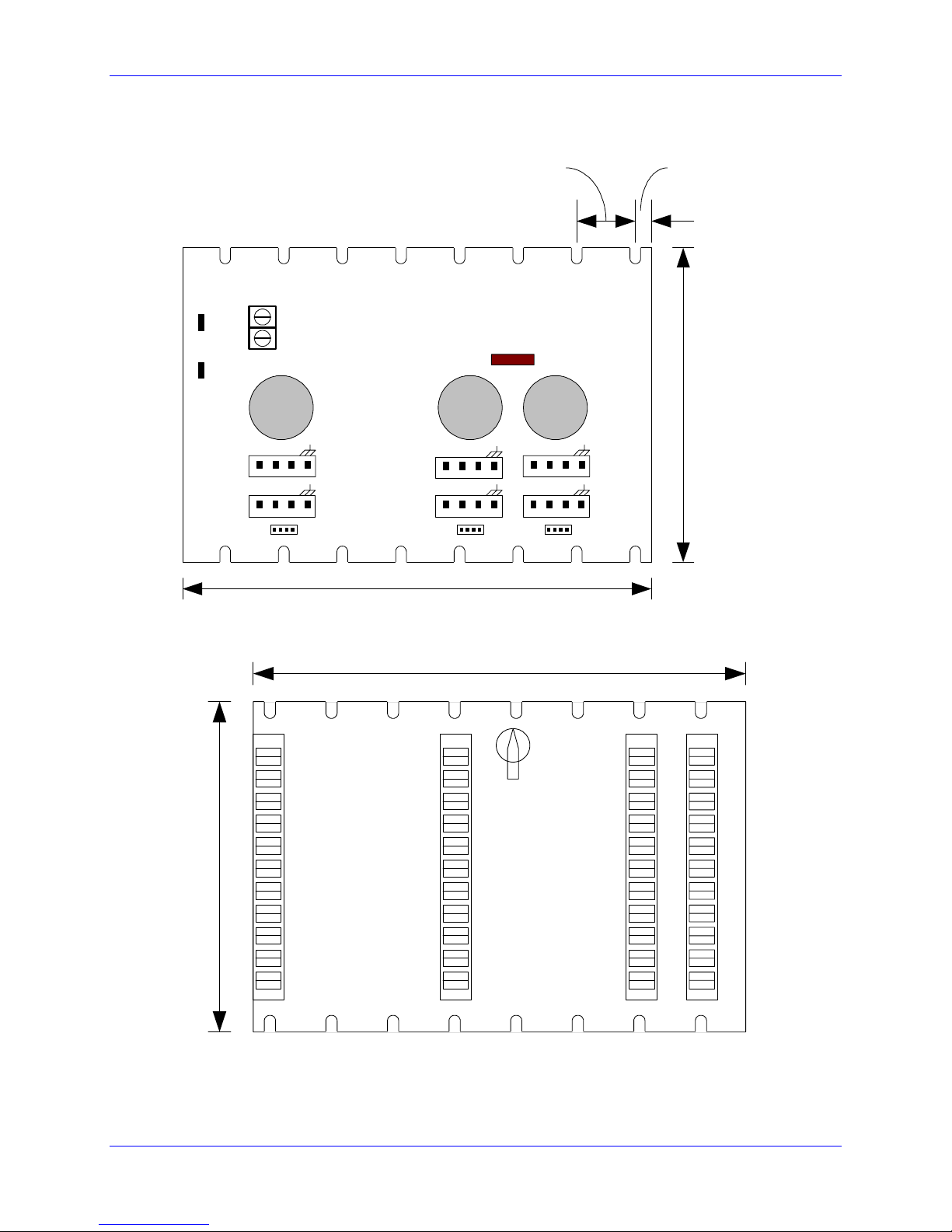
3U Amplifier Backplane Layout (Back)
A B C J7
AXIS 1
1
A B C
AXIS 3 1
J9
A B C
AXIS 4 1
J10 1
A B C J8
AXIS 2
A B C J11
AXIS 5
1
1
A B C J12
AXIS 6
J2 J1 SHUNT
SHUNT
RETURN
BUSIN+
BUSIN-
1
1J15 1J14 1J13
4.92
6.25''
0.216''0.8175''
3U Amplifier Backplane Layout (Front)
4.92
6.25''
LP1
J3 J4 J5 J6

3U Digital PWM Amplifier User Manual
12 3U Amplifier Backplane Board (603435-10x)

3U Digital PWM Amplifier User Manual
Troubleshooting
13
TROUBLESHOOTING
Amplifier stops and displays a code
If a 3U amplifier displays other digit than 0, please refer to a section ‘Protection’ for an explanation of
fault codes.
Amplifier is ‘dark’
If the amplifier status display, +5V, +12V, -12V, ENA1, and ENA2 are not illuminated, verify that DC
bus is connected to the 3U amplifier.
If the condition described above is present, and the 3U amp is used in a UMAC rack along with a power
supply, verify that AC line is connected to the power supply.
Motor does not move upon a command
Verify that PWM cables and motor leads are correctly connected to 3U amplifier. Is motor properly
phased?
Cannot phase a motor
Verify that PMAC is properly configured and sees the motor’s feedback.

3U Digital PWM Amplifier User Manual
14 Troubleshooting

3U Digital PWM Amplifier User Manual
Useful Notes
1
5
USEFUL NOTES
If a shunt (regen) resistor is required, use the shunt terminals on the backplane. Or, the shunt resistor can
be connected directly to the 3U power board (300-603391-102) between J11 pin 5 and J11 pin 4.
The long pin on the power board connector J11 represents pin 11 (Axis #2 U phase).
If the 3U amplifier is not used in Delta Tau UMAC rack, it is a user’s responsibility to assure that the
proper cooling is provided for the IGBTs. Delta Tau suggests a fan capable of at least 100 CFM placed as
close to the heatsinks as possible.
If the bus connection to the 3U amp is not done via Delta Tau backplane, a de-coupling capacitor (about
120 µF) for + and – bus should be used.

3U Digital PWM Amplifier User Manual
Useful Notes
1
6
Table of contents
Other Delta Tau Amplifier manuals


