Delta Tau Power Brick AC User manual

Single Source Machine Control ……………………………………………..…...………………. Power // Flexibility // Ease of Use
21314 Lassen St. Chatsworth, CA 91311 // Tel. (818) 998-2095 Fax. (818) 998-7807 // www.deltatau.com
^3 Programmable Servo Amplifier
^3 Low Voltage Programmable Servo Amplifier
^4 PBAx-xxx-xxx-xxxxxxx
^4
^5 July 19, 2017
^5 January 2, 2014
^1 USER MANUAL
^2 Power Brick AC
^2 Power Brick AC
DELTA TAU
Data Systems, Inc.
NEW IDEAS IN MOTION …

Power Brick AC User Manual
Copyright Information
© 2017 Delta Tau Data Systems, Inc. All rights reserved.
This document is furnished for the customers of Delta Tau Data Systems, Inc. Other uses are unauthorized
without written permission of Delta Tau Data Systems, Inc. Information contained in this manual may be
updated from time-to-time due to product improvements, etc., and may not conform in every respect to
former issues.
To report errors or inconsistencies, call or email:
Delta Tau Data Systems, Inc. Technical Support
Phone: +1 (818) 717-5656
Fax: +1 (818) 998-7807
Email: support@deltatau.com
Web: www.deltatau.com
Operating Conditions
All Delta Tau Data Systems, Inc. motion controller, accessory, and amplifier products contain static
sensitive components that can be damaged by incorrect handling. When installing or handling Delta Tau
Data Systems, Inc. products, avoid contact with highly insulated materials. Only qualified personnel should
be allowed to handle this equipment.
In the case of industrial applications, we expect our products to be protected from hazardous or conductive
materials and/or environments that could cause harm to the controller by damaging components or causing
electrical shorts. When our products are used in an industrial environment, install them into an industrial
electrical cabinet to protect them from excessive or corrosive moisture, abnormal ambient temperatures,
and conductive materials. If Delta Tau Data Systems, Inc. products are directly exposed to hazardous or
conductive materials and/or environments, we cannot guarantee their operation.

Power Brick AC User Manual
Safety Instructions
Qualified personnel must transport, assemble, install, and maintain this equipment. Properly qualified
personnel are persons who are familiar with the transport, assembly, installation, and operation of
equipment. The qualified personnel must know and observe the following standards and regulations:
IEC364resp.CENELEC HD 384 or DIN VDE 0100
IEC report 664 or DIN VDE 0110
National regulations for safety and accident prevention or VBG 4
Incorrect handling of products can result in injury and damage to persons and machinery. Strictly adhere
to the installation instructions. Electrical safety is provided through a low-resistance earth connection. It is
vital to ensure that all system components are connected to earth ground.
This product contains components that are sensitive to static electricity and can be damaged by incorrect
handling. Avoid contact with high insulating materials (artificial fabrics, plastic film, etc.). Place the
product on a conductive surface. Discharge any possible static electricity build-up by touching an
unpainted, metal, grounded surface before touching the equipment.
Keep all covers and cabinet doors shut during operation. Be aware that during operation, the product has
electrically charged components and hot surfaces. Control and power cables can carry a high voltage, even
whenthe motor isnot rotating. Never disconnect or connect theproduct whilethepower source is energized
to avoid electric arcing.
A Warning identifies hazards that could result in personal injury or
death. It precedes the discussion of interest.
Warning
Caution
A Caution identifies hazards that could result in equipment damage. It
precedes the discussion of interest.
Note
A Note identifies information critical to the understanding or use of the
equipment. It follows the discussion of interest.

Power Brick AC User Manual
MANUAL REVISION HISTORY
REV
DESCRIPTION
DATE
CHANGE
APPROVED
0
Preliminary
05/28/2014
RN
RN
1
Released
07/20/2015
RN
RN
2
Updated I/O & Flags electrical specifications
Updated power–up procedure
Updated absolute power-on position
and ongoing phase position
Added A16 connector description
Corrected serial clock/data pinouts
Added factory reset, firmware reload procedures
Added IP address change procedure
Added AC induction motor setup
Corrected Logic Power Connector Part Number
Added Resolver Configuration
Added Digital Tracking Filter Setup
Added Serial Port RS-232 Description
Modified STO Silkscreen Warning
General Updates and Formatting
05/19/2016
DCDP
/
RN
RN
3
Corrected I2T Settings
General Corrections & Formatting
Added General Purpose I/Os Schematic Snippets
12/13/2016
RN
RN
4
Added Shunt Info
Updated DC Brush Section & Current Loop
Corrected External 5V Mating Connector PN
Added Analog I/Os Schematic Snippets
Added Limits & Flags Schematic Snippets
Changed PwmSf to 95% of 16384
Removed /24in AbsPhasePosSf 20-bit example
Corrected GAR rating in electrical spec tables
Updated X9-X12 DAC output example
Added a note about scaling to user engineering
units
General Formatting
07/19/2017
RN
RN


Power Brick AC User Manual
Table of Contents vi
Table of Contents
INTRODUCTION...................................................................................................................11
Documentation..........................................................................................................................11
Downloadable Power PMAC Script...........................................................................................12
RECEIVING AND UNPACKING .........................................................................................13
Use of Equipment .....................................................................................................................13
SPECIFICATIONS.................................................................................................................14
Part Number Designation..........................................................................................................14
Power Brick AC Configuration...................................................................................................16
Standard Configuration....................................................................................................................16
Options ............................................................................................................................................17
Configuration Notes .........................................................................................................................18
Environmental Specifications....................................................................................................19
Protection Specifications...........................................................................................................20
Electrical Specifications ............................................................................................................21
4-Axis Power Brick AC.....................................................................................................................21
6-Axis Power Brick AC.....................................................................................................................22
8-Axis Power Brick AC.....................................................................................................................23
Mounting...................................................................................................................................24
Physical Specifications..............................................................................................................25
4–axis Power Brick AC.....................................................................................................................25
6–/ 8–axis Power Brick AC..............................................................................................................26
CONNECTIONS AND SOFTWARE SETUP.......................................................................27
A1 –A8: Motor / Brake Wiring...................................................................................................27
Configuring the Brake Output...........................................................................................................29
Motor Cable, Noise Elimination .......................................................................................................30
Motor Selection................................................................................................................................31
A10: Logic Power Input.............................................................................................................33
A11: Safe Torque Off STO, Dynamic Braking...........................................................................34
Disabling the STO............................................................................................................................35
Wiring and Using the STO................................................................................................................35
Wiring and Using the Dynamic Braking............................................................................................36
A12: Brake Power (Axes 1 –4).................................................................................................37
A14: External Shunt Resistor....................................................................................................38
A15: Main Bus Power Input.......................................................................................................39
Advised Power On/Off Sequence.......................................................................................................40
Recommended Main Bus Power Wiring / Protection.........................................................................41
A16: Brake Power (Axes 5 –8).................................................................................................45
X1 - X8: Encoder Feedback, Digital Quadrature........................................................................46
Configuring Quadrature Encoders....................................................................................................48
Quadrature Counts per User Units...................................................................................................48

Power Brick AC User Manual
Table of Contents vii
X1 - X8: Encoder Feedback, Sinusoidal....................................................................................50
Configuring Sinusoidal Encoders .....................................................................................................51
Sinusoidal Counts per User Units.....................................................................................................52
X1 –X8: Encoder Feedback, Resolver......................................................................................54
Setting up Resolvers .........................................................................................................................55
Configuring Resolver ECT................................................................................................................56
Resolver Counts per User Units........................................................................................................56
Resolver Absolute Power-On Position ..............................................................................................57
X1 –X8: Encoder Feedback, Serial ..........................................................................................59
Serial Encoder Control.....................................................................................................................61
Serial Encoder Command.................................................................................................................62
SSI Configuration Example...............................................................................................................63
EnDat 2.1/2.2 Configuration Example..............................................................................................64
Hiperface Configuration Example ....................................................................................................66
Yaskawa Sigma I Configuration Example .........................................................................................68
Yaskawa Sigma II/III/V Configuration Example................................................................................70
Tamagawa FA-Coder Configuration Example..................................................................................72
Panasonic Configuration Example....................................................................................................73
Mitutoyo Configuration Example......................................................................................................75
Kawasaki Configuration Example.....................................................................................................77
Serial Encoder Ongoing Position Setup ....................................................................................78
Serial Encoder Power-On Absolute Position Setup...................................................................83
X9 –X12: Analog Inputs / Outputs............................................................................................89
Setting up the Analog (ADC) Inputs..................................................................................................90
Setting up the Analog (DAC) Outputs ...............................................................................................94
Setting up the General Purpose Relays .............................................................................................98
Setting up the GP Input ..................................................................................................................100
X13: Axis 1 –4 Limits, Flags, EQU .........................................................................................101
X14: Axis 5 –8 Limits, Flags, EQU .........................................................................................102
Wiring the Limits and Flags ...........................................................................................................103
Limits and Flags Suggested Pointers ..............................................................................................104
X15: Digital Inputs / Outputs....................................................................................................106
X16: Digital Inputs / Outputs (Additional).................................................................................107
About the Digital Inputs and Outputs..............................................................................................108
Wiring the Digital Inputs and Outputs ............................................................................................109
X15 Digital I/O Pointers.................................................................................................................110
X16 Digital I/O Pointers.................................................................................................................110
X17: MACRO..........................................................................................................................111
X18: Global Abort and Watchdog............................................................................................112
Abort Input.....................................................................................................................................112
Watchdog Relay .............................................................................................................................114
X19: External Encoder Supply ................................................................................................115
Wiring the Encoder Supply.............................................................................................................115
Functionality, Safety Considerations ..............................................................................................116
X20 –X23: RTETH & Fieldbus................................................................................................117

Power Brick AC User Manual
Table of Contents viii
ETH 0/1: Ethernet Connections...............................................................................................117
ETH 0 Ethernet Port.......................................................................................................................117
ETH 1 Ethernet Port.......................................................................................................................117
ETH 2/3: EtherСAT Connections.............................................................................................118
RS-232 Connection.................................................................................................................119
MANUAL MOTOR SETUP.................................................................................................120
Global Reset...........................................................................................................................121
Dominant Clock Frequencies..................................................................................................122
Recommended Clock Frequencies...................................................................................................123
Data Unpacking ......................................................................................................................124
Setting up the BrickAC Structure Elements.............................................................................125
Power-On Reset PLC..............................................................................................................126
Verifying Encoder Feedback...................................................................................................128
Configuring the Abort Input .....................................................................................................129
Brushless Motors....................................................................................................................130
Common Brushless Motor Setup Elements (e.g. Motor #1)..............................................................131
PWM Output Scale Factor..............................................................................................................131
Ongoing Phase Position.................................................................................................................132
I2T Protection................................................................................................................................135
Current Loop tuning.......................................................................................................................137
Motor Phasing................................................................................................................................139
Open Loop Test..............................................................................................................................145
Position Loop Tuning.....................................................................................................................147
Absolute Power-On Phasing...........................................................................................................150
DC Brush Motors ....................................................................................................................160
Common DC Brush Motor Setup Elements (e.g. Motor #1).............................................................161
PWM Output Scale Factor..............................................................................................................161
I2T Protection................................................................................................................................161
Current Loop Tuning......................................................................................................................163
Open Loop Test..............................................................................................................................165
Position Loop Tuning.....................................................................................................................166
AC Induction Motors................................................................................................................167
Common AC Induction Motor Setup Elements ................................................................................168
PWM Output Scale Factor..............................................................................................................168
Ongoing Phase Position.................................................................................................................168
Magnetization Current and Slip Gain .............................................................................................169
I2T Protection................................................................................................................................171
ADC Offsets ...................................................................................................................................172
Current Loop Tuning......................................................................................................................172
Motor Phasing................................................................................................................................172
Open Loop Test..............................................................................................................................172
Optimizing Magnetization Current..................................................................................................173
Position Loop Tuning.....................................................................................................................173
SPECIAL FUNCTIONS & TROUBLESHOOTING ..........................................................174

Power Brick AC User Manual
Table of Contents ix
D1: Error Codes......................................................................................................................174
Step and Direction, PFM Output .............................................................................................175
Sinusoidal Encoder Bias Corrections ......................................................................................178
Reversing Motor Jogging Direction .........................................................................................184
PLC Timer Delay.....................................................................................................................185
Encoder Count Error...............................................................................................................186
Encoder Loss Detection..........................................................................................................187
Digital Quadrature.........................................................................................................................188
Sinusoidal | Resolver | HiperFace Encoders ...................................................................................189
Serial Encoders..............................................................................................................................190
Digital Tracking Filter ..............................................................................................................191
PTC Motor Thermal Input........................................................................................................193
LED Status..............................................................................................................................194
Reloading Power PMAC Firmware..........................................................................................195
Changing Network (IP Address) Settings................................................................................198
Restoring Factory Default Configuration..................................................................................200
Watchdog Faults.....................................................................................................................201
BRICKAC STRUCTURE ELEMENTS ..............................................................................202
Global Saved Setup Elements ................................................................................................203
BrickAC.MonitorPeriod..................................................................................................................203
BrickAC.SinglePhaseIn ..................................................................................................................204
BrickAC.UnderVoltageDisplay.......................................................................................................205
BrickAC.UnderVoltageWarnOnly...................................................................................................206
Global Non-Saved Setup Elements.........................................................................................207
BrickAC.Config..............................................................................................................................207
BrickAC.Monitor............................................................................................................................209
BrickAC.Reset................................................................................................................................211
Global Status Elements...........................................................................................................212
BrickAC.BusOverVoltage...............................................................................................................212
BrickAC.BusUnderVoltage.............................................................................................................213
BrickAC.BusVoltage.......................................................................................................................213
BrickAC.LineOk.............................................................................................................................213
BrickAC.PhaseInMissing................................................................................................................214
BrickAC.PowerBoardId..................................................................................................................214
BrickAC.PowerFault ......................................................................................................................214
BrickAC.RegenFault.......................................................................................................................215
BrickAC.RegenOverLoad ...............................................................................................................215
BrickAC.SoftStartFault...................................................................................................................216
BrickAC.STO0................................................................................................................................216
BrickAC.STO1................................................................................................................................217
BrickAC.UnderVoltageMasked.......................................................................................................218
BrickACVers ..................................................................................................................................218
Channel Saved Setup Elements .............................................................................................219
BrickAC.Chan[j].I2tWarnOnly.......................................................................................................219

Power Brick AC User Manual
Table of Contents x
Channel Status Elements........................................................................................................220
BrickAC.Chan[j].I2tExcess.............................................................................................................220
BrickAC.Chan[j].IgbtOverTempFault.............................................................................................221
BrickAC.Chan[j].IgbtTemp.............................................................................................................221
BrickAC.Chan[j].InvalidPwmFreq .................................................................................................222
BrickAC.Chan[j].OverCurrent .......................................................................................................223
BrickAC.Chan[j].OverTemp...........................................................................................................223
BrickAC.Chan[j].PwmFreq ............................................................................................................224
APPENDIX A: DIGITAL INPUTS SCHEMATIC.............................................................225
APPENDIX B: DIGITAL OUTPUTS SCHEMATIC .........................................................226
APPENDIX C: ANALOG I/OS SCHEMATICS.................................................................227
APPENDIX D: LIMITS & FLAGS SCHEMATIC.............................................................229

Power Brick AC User Manual
Introduction 11
INTRODUCTION
The Power Brick AC is a smart servo drive package. It combines the intelligence and capability of the
Power PMAC motion controller with high performance IGBT-based drives resulting into a 4-, 6-, or 8-axis
compact smart drive.
The Power Brick AC is designed for up to 240 VAC main input power. It supports virtually any type of
feedback device and can drive directly the following types of motors:
➢3-phase AC/DC brushless servo (synchronous) –rotary/linear
➢AC Induction (asynchronous) –with or without encoder
➢2-phase DC brush
Note
The Power Brick AC can also provide pulse and direction PFM output
signals to third-party stepper drives.
The number of axes in a Power Brick AC application can be expanded through MACRO or EtherCat.
The Power Brick AC carries onboard up to 32 digital inputs and 16 digital outputs (I/Os) which can also be
expanded through MACRO, ModBus, or EtherCat.
The trajectory planner, built-in software PLCs (programmable in Power PMAC script and / or C language),
and safety features make the Power Brick AC a fully scalable machine automation controller-drive which
can be integrated in virtually any kind of motion control application.
Documentation
In conjunction with this manual, the following manuals are essential for the proper operation and use of the
Power Brick AC:
➢Power PMAC Software Reference Manual
➢Power PMAC User Manual
These manuals are available for download, to registered members, at Delta Tau Forums.

Power Brick AC User Manual
Introduction 12
Downloadable Power PMAC Script
Caution
Some code snippets may require the user to input specific information
pertaining to their system application. Occasionally, they are denoted
in a commentary ending with –User Input.
This manual contains downloadable code snippets in Power PMAC script. These examples can be copied
and pasted into the editor area of the IDE software. Care must be taken when using pre-configured Power
PMAC code, some information may need to be updated to match hardware or system specific
configurations. Downloadable code found in this manual is enclosed in the following format:
// POWER PMAC SCRIPT CODE EXAMPLE
GLOBAL MyCounter = 0; // Arbitrary global variable, counter
GLOBAL MyCycles = 10; // Arbitrary global variable, number of cycles --User Input
OPEN PLC ExamplePLC // Open PLC buffer
WHILE (MyCounter < MyCycles) // While counter is less than number of cycles
{ // Start while loop
MyCounter ++ // Increment MyCounter by 1
} // End while loop
MyCounter = 0 // Reset Mycounter
DISABLE PLC ExamplePLC // Disable PLC
CLOSE // Close PLC buffer
Caution
It is the user’s responsibility to manage the application’s PLCs
properly. The code samples are typically enclosed in a PLC buffer
with the user defined name ExamplePLC.
It is the user’s responsibility to use the PLC examples presented in this manual properly, and incorporate
the statement code in the application project accordingly.

Power Brick AC User Manual
Receiving and Unpacking 13
RECEIVING AND UNPACKING
Delta Tau products are thoroughly tested at the factory and carefully packaged for shipment. When the
Power Brick AC is received, there are several things to be done immediately:
•Observe the condition of the shipping container and report any damage immediately to the commercial
carrier that delivered the package.
•Remove the equipment from the shipping container and remove all packing materials. Check all
shipping material for connector kits, documentation, or other small pieces of equipment. Be aware that
some connector kits and other equipment pieces may be quite small and can be accidentally discarded
if care is not used when unpacking the equipment. Thecontainer and packing materials may be retained
for future shipment.
•Verify that the part number of the product received is the same as the part number listed on the purchase
order.
•Inspect the equipment for external physical damage that may have been sustained during shipment and
report any damage immediately to the commercial carrier.
•Electronic components in this product are design-hardened to reduce static sensitivity. However, use
proper procedures when handling the equipment.
•If the equipment is to be stored for several weeks before use, be sure that it is stored in a location that
conforms to published storage humidity and temperature specifications.
Use of Equipment
The following restrictions will ensure the proper use of the Power Brick AC:
•The components built into electrical equipment or machines can be used only as integral components
of such equipment.
•The Power Brick AC must not be operated on power supply networks without a ground or with an
asymmetrical ground.
•If the Power Brick AC is used in residential areas, or in business or commercial premises, implement
additional filtering measures.
•The Power Brick AC may be operated only in a closed switchgear cabinet, taking into account the
ambient conditions defined in the environmental specifications.
Power Brick AC User Manual
Specifications 14
SPECIFICATIONS
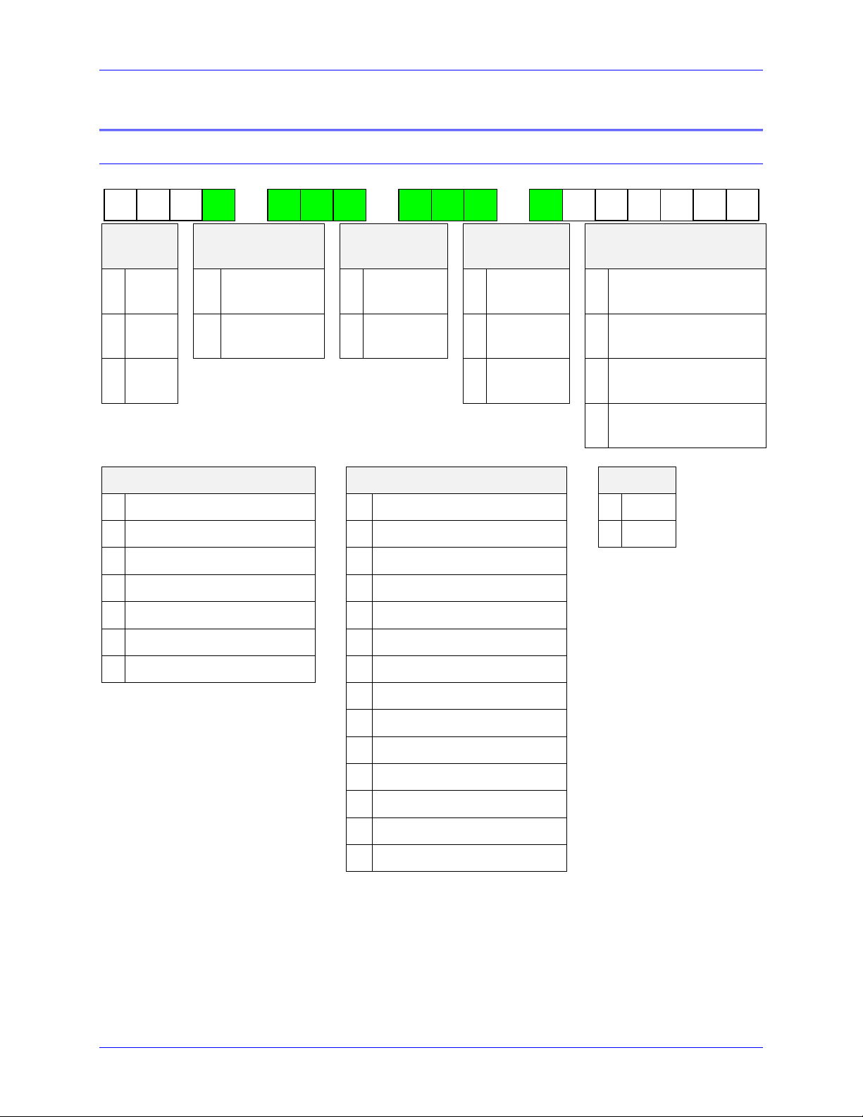
Part Number Designation
B C DA
P B A ---
E F G H I K L
0 0 0
Option
A
Option B
Option C
Option D
Option E
4
4-
axis
G
800 MHz
CPU
1
1 GB
RAM
1
1 GB
Flash
0
1 Gbs EtherNet
6
6-
axis
H
1.0 GHz CPU
2
2 GB
RAM
3
4 GB
Flash
3
1 extra Eth /
EtherCAT
8
8-
axis
4
8 GB
Flash
4
2 extra Eth /
EtherCAT
5
3 extra Eth /
EtherCAT
Option F
Option G
Option H
0
No EtherCAT
0
No Gateway
5
5/10A
1
EtherCAT I/O Only
1
Profibus –DP Master
8
8/16A
2
4 EtherCAT Servo and I/O
2
Profibus –DP Slave
3
8 EtherCAT Servo and I/O
3
DeviceNet Master
4
16 EtherCAT Servo and I/O
4
DeviceNet Slave
5
32 EtherCAT Servo and I/O
5
CANopen Master
6
64 EtherCAT Servo and I/O
6
CANopen Slave
7
CC-Link Slave
9
EtherCAT Slave
A
Ethernet IP Scanner / Master
B
Ethernet IP Adapter / Slave
C
Open ModBus/TCP
E
ProfiNet IO RT Controller
F
ProfiNet IO RT Device

Power Brick AC User Manual
Specifications 15
B C DA
P B A ---
E F G H I K L
0 0 0
Option I
Axis
5-6
Axis
7-8
Encoder
Inputs
Digital
I/Os
MACRO Nodes
Servo / IOs
True DAC
Analog Out
Filtered PWM
Analog Out
Analog
Inputs
GP
Relays
0
-
-
4
16/8
-
-
-
-
-
1
-
-
4
16/8
16/12
-
4
4
4
2
-
-
8
32/16
-
-
-
-
-
3
-
-
8
32/16
32/24
-
8
8
8
4
-
-
8
32/16
32/24
4
4
8
8
F
15/30A
-
8
32/16
-
-
-
-
-
G
15/30A
-
8
32/16
32/24
-
8
8
8
H
15/30A
-
8
32/16
32/24
4
4
8
8
5
5/10A
8
32/16
-
-
-
-
-
6
5/10A
8
32/16
32/24
-
8
8
8
8
8/16A
8
32/16
-
-
-
-
-
9
8/16A
8
32/16
32/24
-
8
8
8
Option K
Option L (ACC-84B)
1 –4
5 –8
1 –4
5 –8
0
-
-
0
-
-
1
Sinusoidal
-
2
SSI
-
2
Resolver
-
3
EnDat
-
3
ACI
-
4
Hiperface
-
5
Sinusoidal
Sinusoidal
6
Yaskawa
-
6
Sinusoidal
Resolver
7
Tamagawa
-
7
Resolver
Sinusoidal
8
Panasonic
-
A
Resolver
Resolver
9
Mitutoyo
-
B
Resolver
ACI
B
BiSS B/C
-
E
ACI
ACI
C
Matsushita
-
F
ACI
Resolver
D
Mitsubishi
-
J
SSI
K
EnDat
L
Hiperface
P
Yaskawa
Q
Tamagawa
R
Panasonic
T
Mitutoyo
V
BiSS B/C
W
Matsushita
X
Mitsubishi

Power Brick AC User Manual
Specifications 16
Power Brick AC Configuration
The Power Brick AC comes standard with a powerful set of hardware and software capabilities, plus a full
set of options.
Standard Configuration
CPU
800 MHz Single-Core Power PC 460EX.
Memory
2 GB DDRAM3 active, 1 GB NAND Flash non-volatile.
Communication
Ports
2 x Gbs Ethernet port for host communication.
RS-232 Serial Port.
USB 2.0 Host port.
USB 2.0 Device port.
Digital I/O
16 x Inputs, fully protected at 12 –24 V sourcing or sinking (user wiring).
8 x Outputs, fully protected at 12 –24 V sourcing or sinking (user wiring).
Servo
Interface
4 channels servo interface, each including:
Quadrature encoder (differential, with index) interface.
UVW digital hall sensor interface.
Serial encoder interface, with software selectable protocol, from the following:
oSSI
oEnDat 2.1 / 2.2 (2.1-compatible features only) with delay compensation
oHiperface
oYaskawa Sigma I
oYaskawa Sigma II / III / V (no position reset or fault clear)
oTamagawa FA-Coder (no servo clock output)
oPanasonic (no servo clock output)
oMitutoyo
oKawasaki
Pulse & direction output.
Position compare (EQU) output (5 V TTL).
Input flags (home, + limit, –limit, user) at 5 –24 V.
Motor thermal input (PTC).
Amplifier
Output
4 amplifier axes, each at 5/10A with 24V brake output.
Amplifier Safety
& Features
Internal shunt / bleeding resistor built-in.
External shunt connection.
Shunt resistor fault detection.
Hardware I2T thermal fault detection.
Short circuit detection.
IGBT over-temperature detection.
PWM frequency out-of-range detection.
No bus voltage detection.
Soft start fault detection.
Watchdog output (normally closed / open).
Abort Input (category 2 stop).
STO Input (category 0 stop).

Power Brick AC User Manual
Specifications 17
Options
CPU
1 GHz Single-Core Power PC 460EX.
Memory
2 GB DDRAM3 active, 4 or 8 GB NAND Flash non-volatile.
Communication
Ports
1 or 2 x additional Gbs Ethernet ports, EtherCAT compatible.
Digital I/O
Additional 16 x Inputs, fully protected at 12 –24 V sourcing or sinking (user
wiring).
Additional 8 x Outputs, fully protected at 12 –24 V sourcing or sinking (user
wiring).
Analog I/O
4 or 8 x 16-bit analog inputs.
4 or 8 x 14-bit filtered PWM analog outputs (±10 V).
4 x 16-bit true DAC analog outputs (±10 V).
4 or 8 x Amp enable outputs (to 3rd party drives).
4 or 8 x Amp fault inputs (from 3rd party drives).
Servo
Interface
4 additional channels servo interface including the same as the standard features.
Sinusoidal encoder interface.
Resolver encoder interface.
ACC-84B serial encoder protocols:
oMatsushita (Nikon D)
oMitsubishi
oEnDat 2.2 with additional information, no delay compensation
oBiSS-B/C
oYaskawa II/III/V with position reset and fault clear
oTamagawa FA-Coder with servo clock output
oSSI (no capabilities over Power Brick AC’s built-in interface)
oPanasonic (no capabilities over Power Brick AC’s built-in interface)
oMitutoyo (no capabilities over Power Brick AC’s built-in interface)
Amplifier
Output
4 additional amplifier axes, each at 5/10 A or 8/16 A with 24 V brake output.
2 additional amplifier axes, each at 15/30 A with 24 V brake output.
MACRO
Interface
16 Servo, 12 I/O nodes interface.
32 Servo, 24 I/O nodes interface.
EtherCAT
Interface
EtherCAT I/O only.
4 / 8 / 16 / 32 / 64 Servo axes plus I/O.
Fieldbus
oEtherNet / IP Scanner / Master.
oEtherNet / IP Adapter / Slave.
oOpen Modbus / TCP.
oPROFINET IO RT Controller.
oPROFINET IO RT Device.
oCANopen Master.
oCANopen Slave.
oPROFIBUS-DP Master.
oPROFIBUS-DP Slave.
oDeviceNet Master.
oDeviceNet Slave.
oCC-Link Slave.
oEtherCAT Slave.
oModbus.

Power Brick AC User Manual
Specifications 18
Configuration Notes
oQuadrature encoders can always be wired in and processed regardless of the feedback options fitted.
oThe following serial encoder protocols are built into (standard) the Power Brick AC –Gate3:
HiperFace
SSI
Panasonic
Kawasaki
EnDat 2.1 / 2.2
Yaskawa II / III / V
Tamagawa
Mitutoyo
Additionally, any of the listed optional protocols can be ordered (in sets of 4 channels: 1 –4 or 5 –8).
These are processed on what is known as the ACC–84B (piggy back inside the Power Brick AC).
Some protocols may overlap between the Gate3 and ACC–84B. Users may need new, updated
protocols, or additional serial data information which may not be available with the standard Gate3
protocol implementation.
oWith the optional ACC-84B installed, a given channel can be configured (in software) to use either one
of the Gate3 serial encoder protocols or one of the ACC-84B protocols.
oIf a serial encoder is used on a given channel, it is also possible to wire in on the same connector and
process simultaneously a quadrature/sinusoidal/resolver encoder.
Note that pins #5, 6, 13, and 14 of the encoder feedback connectors (X1 –X8) share multiple functions:
only one of these functions (per channel) can be used –configured in software –at one time:
➢Hall sensors inputs (default configuration).
➢Pulse and direction PFM output signals (software configuration using Flag D output, OutFlagD).
➢Serial encoder inputs (software configuration enabling serial encoder line, SerialEncEna).
➢Quadrature encoder inputs (serial encoder enable line must be 0).
➢Alternate Sinusoidal encoder inputs (with sinusoidal encoder option).
Note
Each channel is independent of the other channels and can have its
own use for these pins.

Power Brick AC User Manual
Specifications 19
Environmental Specifications
Specification
Description
Range
Ambient operating Temperature
EN50178 Class 3K3 –IEC721-3-3
Minimum operating temperature
0°C (32 °F)
Maximum operating temperature
45°C (113 °F)
Storage Temperature Range
EN 50178 Class 1K4 –IEC721-3-1/2
Minimum Storage temperature
-25°C (-13 °F)
Maximum Storage temperature
70°C (158 °F)
Humidity Characteristics with
NO condensation and NO formation of ice
IEC721-3-3
Minimum Relative Humidity
10% HU
Maximum Relative Humidity
up to 35 °C (95 °F)
95% HU
Maximum Relative Humidity
from 35 °C up to 50 °C (122 °F)
85% HU
De-rating for Altitude
0 ~ 1000m (0 ~ 3300ft)
No de-rating
1000 ~ 3000 m (3300 ~ 9840 ft)
-0.01% / m
3000 ~ 4000 m (9840 ~ 13000 ft)
-0.02% / m
Environment
ISA 71-04
Degree 2 environments
Atmospheric Pressure
EN50178 class 2K3
70 kPa to 106 kPa
Shock
Unspecified
Vibration
Unspecified
Air Flow Clearances
3" (76.2 mm) above and below unit for air flow
Cooling
Natural convection and external fan
Standard IP Protection
IP20
IP 55 can be evaluated for custom applications
Note
Above 40°C ambient, de-rate current output by 2.5% per °C.

Power Brick AC User Manual
Specifications 20
Protection Specifications
Caution
The internal I2T applies to and protects the amplifier power blocks.
The software PMAC I2T (described in a later section) must be
configured properly to protect against motor / equipment damage.
Description
Specifications
Over Voltage
~ 307 VAC / 435 VDC (±2 %)
Under Voltage
~ 70 VAC / 100 VDC (±5 %)
AC Phase Loss Detection
Loss of one or more phases (single & three-phase operation)
Internal I2T protection
2 seconds at rated peak Amps per axis
Over Temperature
~ 75C
Motor Short Circuit
500 % of rated peak Amps per axis
Over Current
110 % of rated peak Amps per axis
Shunt I2T Detection
Integrated, I2T model at 2 seconds peak
Shunt Short Detection
Shunt IGBT short circuit protection
Shunt Turn On Threshold
380 VDC
Shunt Turn Off Threshold
405 VDC
Soft Start Short Detection
Soft Start short circuit protection
PWM Out Of Range
Out of [4 –20] kHz, or on-time exceeds 1.4 msec
Safe Torque Off STO
Cut off gate driver/motor power
Note
The under voltage fault triggers when the AC Input dips below 70
VAC (100 VDC). However, if this threshold has not been reached (i.e.
Low Voltage/DC operation) the under voltage logic remains unarmed.
Table of contents
Other Delta Tau Amplifier manuals


Popular Amplifier manuals by other brands


Rockford Fosgate
Rockford Fosgate Power T1500-1bd Installation & operation

Crystal Vision
Crystal Vision Indigo AADA416FM user manual

Synapse
Synapse DAD08 manual

Rogue Audio
Rogue Audio Sphinx II owner's manual

Crest Audio
Crest Audio CA9 Specifications

bonitron
bonitron Legacy M3534R-RY Customer Reference Manual