HiBoost F27-5S User manual

User'sManual
F27-5S
MADE IN HUAPTEC

TableofContents
Tableof Contents ..............................................................................................2
Operation .........................................................................................................3
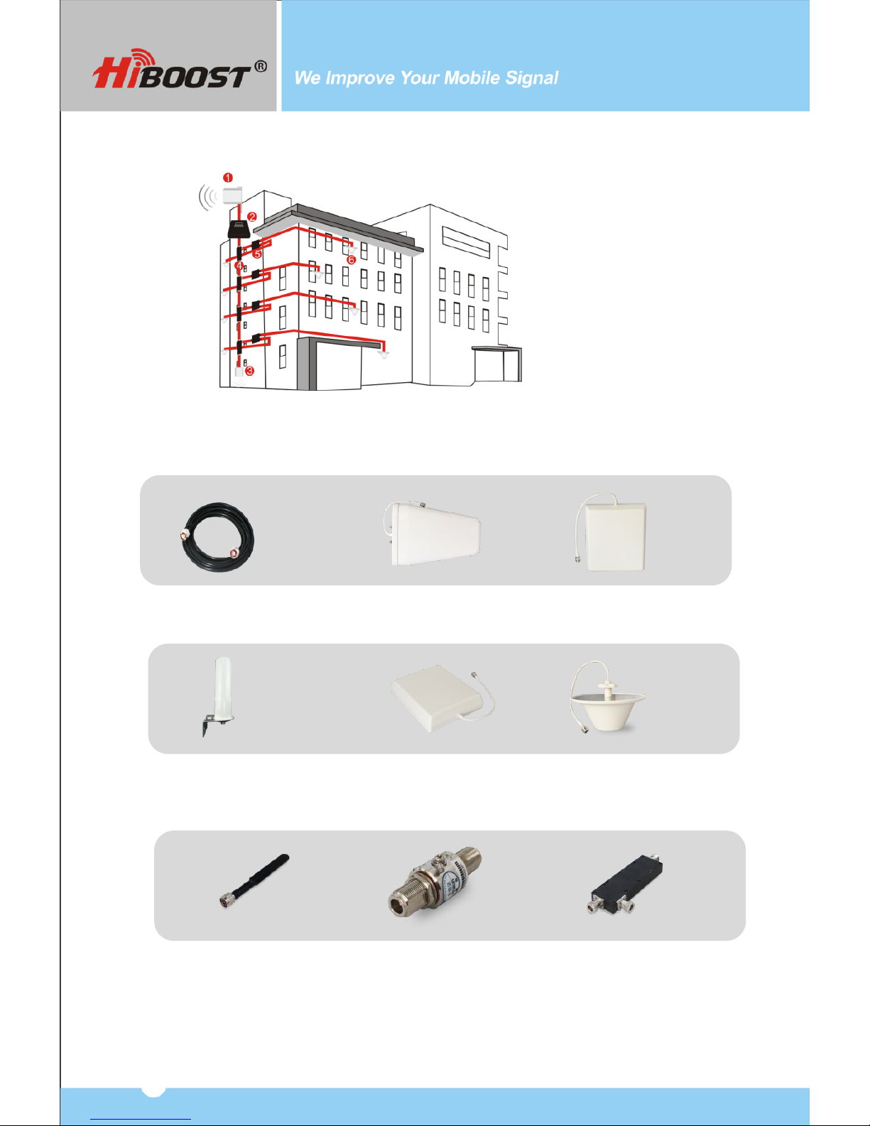
Package Contents............................................................................................3
Key Features.....................................................................................................5
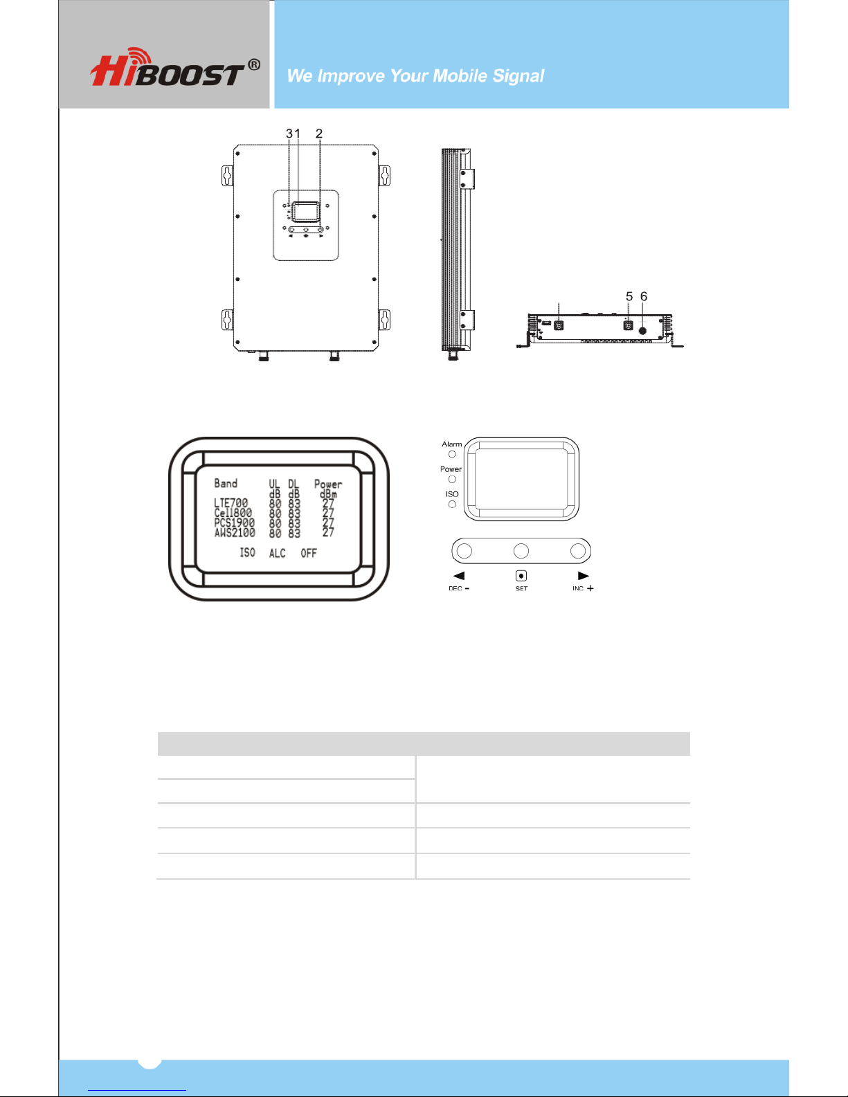
Key Components..............................................................................................5
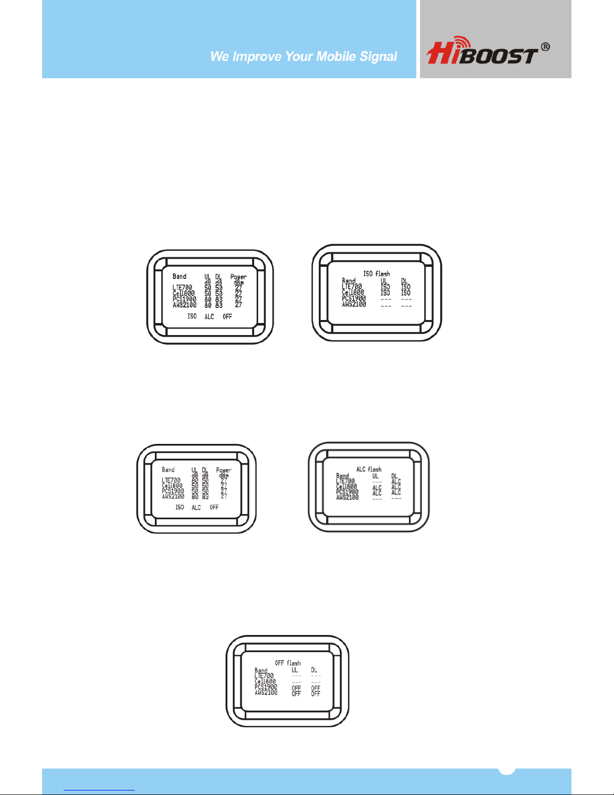
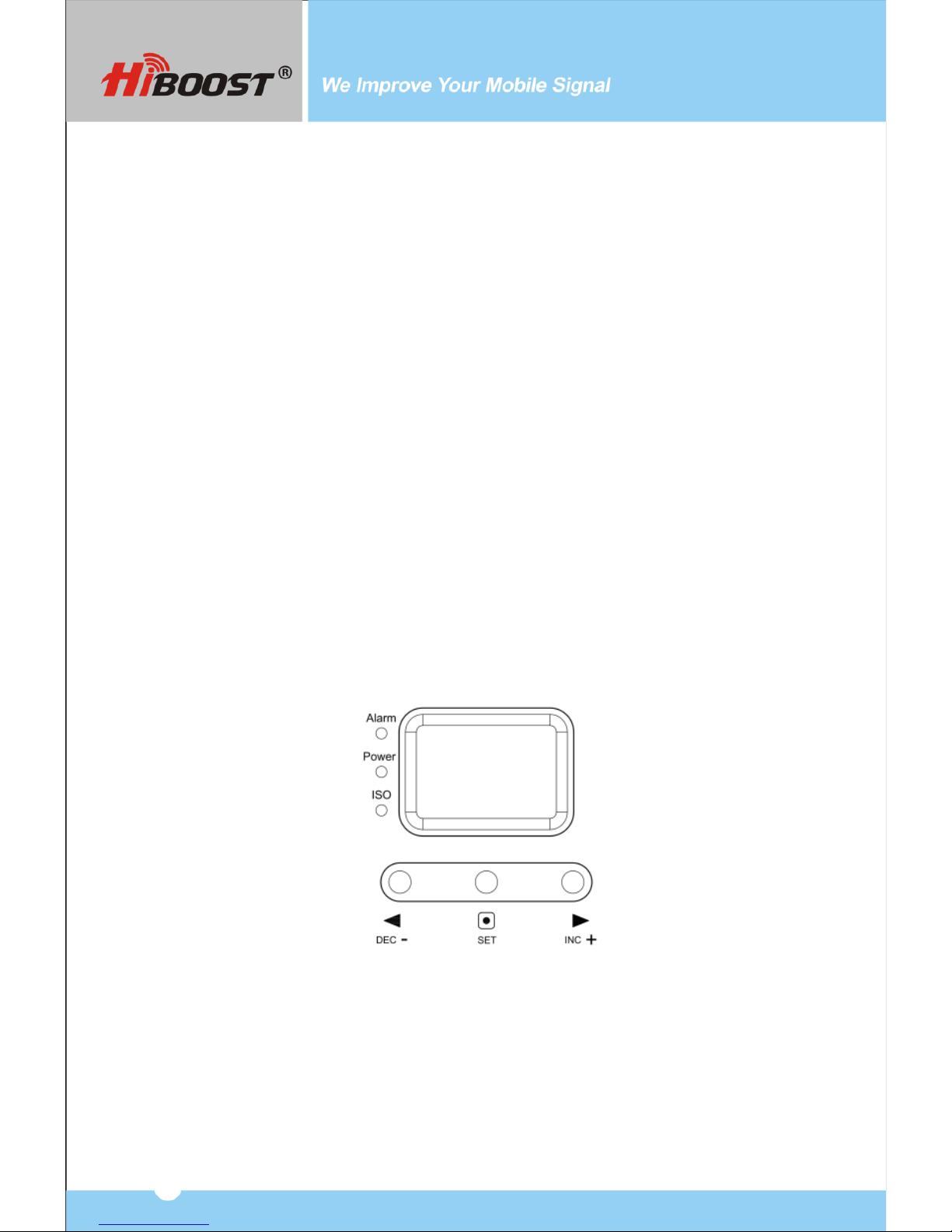
LCD Features ....................................................................................................6
Manual Gain Control Operation ....................................................................8
Manual Gain Control (MGC)..........................................................................9
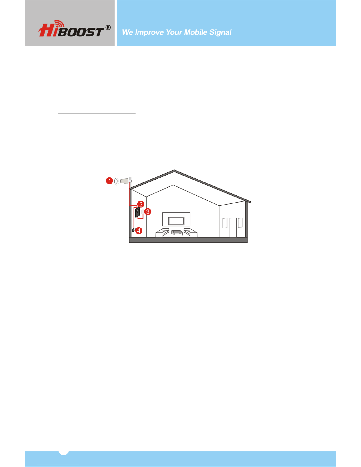
System Installation...........................................................................................9
Before You Install ......................................................................................9
Installation Overview..............................................................................10
1.Installation of Outdoor Antenna .........................................................10
2.Installation of Indoor Antenna.............................................................13
3.Install the signal booster ....................................................................14
4.Booster Commissioning ..................................................................... 14
Trouble Shooting ............................................................................................21
Specifications ................................................................................................22
Product Warranty ...........................................................................................22
FCC RF Exposure Statement .........................................................................23
IC RF Exposure Statement .............................................................................23
Warnings.........................................................................................................24
ABBREVIATIONS and PHRASES USED IN THIS MANUAL
ALC: Automatic Level Control
DL: Downlink (Signal transmitted from local cell site tower to phone)
UL: Uplink (Signal transmitted from phone to cell site tower)
MGC: Manual Gain Control
dBm: The power ratio in decibels (dB) of the measured power
referenced to one milliwatt (mW).
YAGI: A type of narrow-beam directional antenna
‘Slow Flashing’: Less than one flash per second
‘Fast Flashing’: More than one flash per second
2

Operation
This manual covers operation, installation and troubleshooting procedures for
the bi-directional amplifier Model: F27-5S.
The F27-5S amplifier is designed to help wireless device users amplify weak
signals of all the major carriers in the 2G, 3G and 4G bands. This bi-directional
amplifier is used to boost uplink signals from the phone to the local cell site
tower and simultaneously amplifying downlink signals transmitted from the
tower to the phone. An antenna located outdoors (donor antenna) receives
signals from the cell site tower, transmits them to the amplifier and then
rebroadcasts them on antennas located indoors to the wireless device. The
indoor antennas also received signals transmitted from the phone that are
boosted in the amplifier and sent to the tower via the outdoor donor antenna.
Package Contents
F27-5S Booster Power Supply 12V/7A
* Outdoor and indoor antennas and cables are required for installation
(purchased separately).
The F27-5S industrial amplifier requires outside and inside antennas connected
with appropriate coaxial cables and a splitter network. The F27-5S can typically
power 8-15 indoor antennas but the exact number of antennas, length of cable
or other accessories needed can vary according to the size and construction
materials used in the building, outdoor signal strength and layout of the structure.
Please contact us for assistance in designing your system.
N
o
.
Name
Description
Quantity
1
Amplifier
F27-5S
1
2
Power Supply
12V/7A
1
3
Plastic Wall Insert
Φ8
5
4
Tapping Screw
M6*50
4
5
User Manual
1
3

Multiple Antenna Installation Sample
1.Outdoor Antenna 2. Booster 3.Indoor Panel Antenna
4. Coupler 5. Splitter 6. Omni Ceiling Antenna
Optional Accessories Recommended
RF Cables Wide Band Yagi Antenna Outdoor Panel Antenna
Outdoor Ceiling Mount Dome Antenna Indoor Panel Antenna Omni Ceiling Antenna
Whip Antenna Lightning Protector Directional Coupler
4

Cavity Splitter (2,3,4 way) Wilkinson Splitter (2,3,4 way)
Key Features
•Self-adaptive Smart Level Control (ALC): Enables convenient ‘plug and play’
installation and optimum coverage in complex and dynamically changing RF
signal environments.
•ISO: Smart isolation gain processing to avoid self-oscillation between
antennas and avoid interference to the carrier network.
•LCD Display: Displays ISO status, ALC status, actual gain and downlink output
power in each band to enable easy installation and troubleshooting.
•MGC: Manual Gain Control adjustments to independently change
gain for both the uplink and downlink, 31dB range.
•Excellent RF Performance: 27 dBm downlink power available to overcome
loss in long cable runs and splitter networks.
•Low Profile Enclosure: Light weight compact wall-mount with low power
consumption and heat dissipation.
Key Components
The following drawing shows the key components of the booster.
1. LCD Display
2. Manual Gain Control Push Buttons
3. LED Indicators
4. Outdoor Antenna Port (Type N-Female)
5. Indoor Antenna Port (Type N-Female)
6. Power Connector
5

LCD Features
After the booster is powered on, uplink (UL) and downlink(DL) gain and DL
output power are displayed. “Band”–Shows the working frequency. Below is a
list of the frequencies displayed corresponding to the Band display shown on
the screen.
“UL (dB)”“DL (dB)”–
Gain Indication.
The displayed value shows real-time uplink and downlink gain. These values
will change slightly as the ALC or ISO makes changes to the gain to optimize
coverage.
Frequency
Band display
700MHz Lower A/B/C blocks
LTE700
700MHz Upper C block
CDMA800&GSM850&UMTS850
Cell800
PCS1900
PCS1900
AWS2100
AWS2100
4
6

“Power dBm
”–Power Indication.
The displayed value shows real-time downlink power that the amplifier is
delivering to the indoor antenna port. When the amplifier DL output power is
lower than -10dBm, the value will display ”---”.
“ISO” –Isolation Alarm Indication.
When the system does not have enough isolation between the outdoor and
indoor antennas, the “ISO” indicators will be flashing showing that the ISO is
lowering the gain in some bands to keep the system from oscillating. Press
the ”SET”key and the LCD screen will display ”ISO” showing the current band
or bands affected.
“ALC” Flashing.
When the amplifier is receiving too much DL power from the tower and the DL
amplifier output is close to saturating, the “ALC” indicators will flash showing that
the ALC has lowered the gain to prevent this overload condition. Press the ”SET”
button and the screen will show the band or bands affected.
”OFF”- Booster shut-off alarm indication.
In some rare situations the ALC or ISO will not be able to compensate for an
oscillation condition or a downlink overload. When this happens the amplifier
will shut off in the affected band and the LCD “OFF” indicator will flash.
Pressing the “SET” button will display which band or bands are affected.
7

Manual Gain Control Operation
There are 4 operation modes relative to the control buttons: a long press for
more than 3 seconds on the “SET”button, short press on the “SET”button, short
press on “DEC-”button and short press on “INC+”button.
When the LCD is in the fixed display mode, press the “SET”key for 3 seconds
and it will start up in the Gain Setting Mode.
Press the “SET”key shortly, and the LCD will switch to the next
value (uplink or downlink gain for a different band).
Press the “INC+” (or “DEC-”) key, and the value of the current g a i n
item will change to a higher (or lower) one.
Press the “SET”key for 3 seconds, and the LCD will return to the fixed
display mode. (For more details refer to Manual Gain Control (MGC)
below.
When the LCD is in the alarm display mode, press the “SET”key and the LCD
screen will display the alarm indication showing the affected band. Pressing the
“INC+” (or “DEC-“) key and the LCD will switch to help tips. If none of keys are
depressed within 30 seconds, the display will return to the fixed display mode.
If none of the control keys are depressed within 5 minutes, the LCD screen will
turn off. Pressing any key will return the display to the fixed mode.
8

Manual Gain Control (MGC)
Since the booster has a very good self-adaptive smart automatic level control
(ALC) and isolation gain processing (ISO) , most of the time manual
adjustments are not required to achieve good coverage. However, in some
cases where the ALC or ISO is working at a very high rate to adjust the gain
and the Alarm or ISO LED is flashing more than once a second a manual
adjustment might be desired.
When the LCD is in the fixed display mode, press the “SET” key for more than 3
seconds. It will go into the “Gain Setting Mode”and make one of the gain
values start to blink.
Press “SET”key shortly, and the LCD will switch to the next gain value
and it will start to blink. (uplink or downlink gain for a different band).
Press “INC+”key once shortly and the gain will increase by 1dB, Press
“DEC-”once shortly and the gain value will be reduced by 1dB.
Press the “SET”key for 3 seconds, and the LCD will return to
the fixed display mode.
Note: When adjusting the gain manually, please ensure that the uplink gain
is equal to or not 5 dB less than the downlink gain setting. This avoids
interference with the local cell site tower network.
System Installation
Before You Install
oMake sure you have sufficient cable length between the proposed
outdoor/indoor antennas and the amplifier
oMake sure the mounting location is near an existing electrical outlet,
well ventilated, away from excessive heat, moisture, and direct sunlight.
Installation tools and accessories:
No.
Name
Specification
Quantity
Remark
1
Plastic wall inserts
Φ8
5
Standard accessories
2
Tapping screws
M6*50
4
Standard accessories
3
Electric Drill
1
4
Drill bit
Ø8
1
9

1
2
3
4
Installation Overview
This amplifier has an LCD display and smart self-adaptive Automatic Level
Control (ALC) and Isolation gain processing (ISO) system. The LCD displays real
time working status and the ALC and ISO can automatically calculate and adjust
the booster gain to obtain its optimum performance. So it is very easy to install.
General installation steps:
1. Install the outdoor antenna on the roof to obtain the strongest downlink
signal from the local cell site towers.
2. Install the indoor antennas where you want to improve the signal level.
3. Mount the amplifier, connect the cables from the outdoor antenna and
indoor antenna at the designated ports, and connect the booster to the AC
supply (make sure all the cables are connected before applying power).
1. Outdoor Antenna 2. Booster 3. Indoor Antenna 4. Power Supply
1. Installation of Outdoor Antenna
1.1 How to find the location with the strongest received signal
The booster’s main function is to improve a weak RF signal inside a house,
office or any other indoor area. The received outdoor downlink signal strength
directly affects the efficiency of the indoor coverage. That is why it is crucially
important to install the antenna at a good location and point it properly
towards a tower where signal reception is the strongest.
There are three methods that can be used to find the strongest downlink signal
from the local towers. One is to use the LCD display on the amplifier that shows the
downlink power output of the amplifier in each band, the other is to use a mobile
phone that shows the signal bars and the third is to use a commercially available
signal strength meter. We highly recommend that you use the LCD display on the
amplifier as this method is generally more accurate. However, in situations where
the desired carrier’s signal is much weaker than the other local signals, using a
signal level meter can be a more accurate method of homing in on the best signal
for an installation.
10

•LCDDisplayMethod
Connect the outdoor antenna to the booster’s outdoor port. Fix the outdoor
antenna on the roof of the building and point it to the nearest cell tower. Then
have a look at gain and output power value displayed on the amplifier’s LCD.
The outdoor antenna receives the strongest signal when the booster’s downlink
output power reaches its highest level in each band.
The booster's LCD display shows the gain and output power. The output power
can be checked below "Power (dBm)" on the LCD display.
NOTE: When the ALC legend is flashing, it means the received signal power is
stronger than the system needs it to be. It is recommended to adjust the outdoor
antenna orientation until the ALC alarm disappears. Or you can leave it as it is to
let the booster self-adjust automatically. However, when the ALC flashes, and
the displayed gain is 30dB less than the amplifier’s rated max gain value, try to
adjust the outdoor antenna to decrease the received signal power from the local
tower. Otherwise it may be necessary to install an attenuator on the outdoor
antenna port to decrease the input signal level from the local tower.
The maximum downlink gain for this model is 83 dB.
•Mobile Phone Method
You can use a telephone to test signal strength on the top of the building. The
number of bars on the network indicator will define approximate strength of the
received signal. Normally the roof of the building is the best place to receive the
strongest signal. As shown on the drawing below, you need to test the signal in
the points from A to E, and select the location with the best signal strength for
outdoor installation. It is recommended to use a mobile app that can display in a
test mode the signal level in dBm units. It is more accurate than checking the
signal bars.
11

A
E
B
D
C
Note: Please try to receive a signal from cell towers that are not overloaded
with multiple users. This can be estimated by the population density in the area
served by the tower. For example, it is recommended to avoid cell towers near
supermarkets, shopping malls, stadiums or any other public places visited by
many people regularly. This will help maintain reliable phone call connections
and higher speed data services.
1.2 Install Outdoor Antenna
In most cases a directional wide band Yagi or panel antenna is the best
outdoor antenna choice.
Mast mounting is recommended for easy installation:
1. Use an existing mast or obtain a mast between 1 to 2 inches in outside
diameter and install it in the desired location.
2. Unscrew nuts from the antenna base. Attached the horizontal plate of the L-
bracket on the antenna base with screws.
3. Unscrew nuts and washers from U-bolt, slide both brackets onto U-bolts.
4. Fit the assembly on the mast in the desired location. Slide the vertical plate
of the L-bracket onto the U-bolt and secure it with the washers and nuts
provided. Before tightening the nuts be sure to fix the antenna at the necessary
height and directed towards the nearest tower. Do not over tighten.
12

Note: Wrap waterproof tape around the connectors between outdoor antenna
and feeder line to avoid moisture ingress.
2. Installation of Indoor Antenna
Select indoor panel antenna or omni-ceiling antenna as an indoor antenna
according to your needs to provide indoor coverage.
Install the indoor panel antenna as shown on the graph below.
1. Select a place on a wall in the area where you need better reception.
2. Drill holes and mount the bracket.
3. Place the panel antenna on the bracket.
When choosing an indoor omni ceiling antenna, the best place to install it is in
the center of area that needs signal improvement. Install the omni ceiling
antenna as shown on the figure below:
1. Drill a hole in the ceiling.
2. Unscrew a fixing nut from the antenna. Pass the antenna cable through the
hole. Screw the fixing nut back onto the antenna, leaving the cable in the
ceiling crawl space, and fasten.
3. Connect N-male cable to the cable connector on the omni ceiling antenna.
4. Tighten the fixing nut to secure the antenna. Do not over tighten.
13

3. Install the signal booster
1. Select an indoor location near a power outlet on a wall. Please use a surge protector
rated at a minimum of 1000 Joules between the amplifier’s power adaptor and the AC
power outlet on the wall.
2. Mount the booster with the included screws as shown in the figure
below.
3. Connect the outdoor antenna cables to the booster connector marked
“outdoor”. Tighten the connection by hand.
4. Connect the indoor antenna cables to the booster connector marked
“indoor”. Tighten the connection by hand.
5. Connect the AC power cord to the signal booster, and then connect the plug
to the surge protector electrical outlet to power on the booster
Booster Installation Antenna Connections
4. Booster Commissioning
Overview: The booster has a very smart startup system. Booster commissioning
is an automatic process designed to guarantee its optimal performance.
After finishing the booster system installation, please power on the booster.
The booster will start its initialization process to check the received downlink
signal from the cell site and the isolation status to ensure its best performance.
This will take approximately 3 - 5 seconds.
After the booster starts up, please check if the coverage is good. If it is good,
the booster system installation is complete.
14

Check the downlink output power displayed by the LCD. It may vary
dynamically at times between 1-3 dB which is normal due to outdoor signal
conditions. It would be optimum that the output power reaches its maximum
rated levels for the largest coverage; but you can always leave it set at lower
levels if the coverage is adequate. Please bear in mind that it is nearly
impossible to achieve 4 - 5 bars on every phone at all locations in a building.
Cellular phones will operate just fine if they are showing 1-2 bars. Some phones
by different manufactures will often show widely different signal level results.
Also, phones by the same manufacture can show different results if they have
different software versions. Because of very large indoor RF signal multipath
effects moving a phone only a few feet can result in large changes in its
received signal level.
If the coverage is not adequate, please take the steps below as is appropriate
for each situation:
1. The rated output power is reached, but the coverage is not enough or the
signal in specific areas has not been improved
•Check whether the indoor antenna is installed correctly. You may try to
move the antenna location to improve coverage.
•If an indoor panel is used, check if adjusting the pointing direction of
the indoor antenna makes any difference.
•Check whether it is necessary to add more indoor antennas since barriers
such as walls will block the signal penetration.
2. The rated downlink output power is not reached.
1) Please adjust the outdoor antenna to get a stronger received signal from
the tower to get higher downlink output power (not necessarily to reach rated
value if the coverage is adequate). The max rated downlink power for this
amplifier is 27 dBm.
2) Please observe the LCD display. If the displayed gain is much less than the
rated value and "ISO" is flashing, it means the gain is being reduced by the ISO
function because there is not enough isolation between an indoor antenna and
the outdoor antenna.
Measures: One of the actions below are recommended to eliminate ISO
problems and increase the gain:
•Adjust the antenna’s pointing directions or locations, or increase the distance
between them.
•Increase the vertical or horizontal distance between the outdoor antenna and
the indoor antenna.
•Use barriers, such as walls, to increase the isolation.
•Change the indoor antenna type to a different antenna type which has a
more directional pattern. Also, you can orient the indoor antennas and
outdoor antenna to point in opposite directions.
15

•Reduce the booster’s downlink gain with the manual gain control buttons.
Keep the uplink gain value and downlink gain values the same then restart the
booster.
•If the indoor antennas are connected through a splitter network locate the
antenna that is causing the ISO alarm by disconnecting each indoor antenna one
at a time and insert an inline attenuator to reduce the signal power going to that
particular antenna.
More about "ISO"indication
ISO status indicates if the booster has enough isolation between outdoor and
indoor antennas to avoid loop back or so-called self-oscillation. Thanks to a
very smart isolation gain processing, this amplifier is fully protected from
creating interference with the carrier’s local cell site networks. "ISO" flashing on
the LCD display means that the ISO function is doing its job and the self-
oscillation has been eliminated.
LCD
Status
Meaning
Solution Methods
ISO
status
Not flashing
No loop back or
no self-
oscillation
No action is needed
Flashing but the
actual gain is not
less than 30dB
below the rated
gain
Slight loop back
or self-
oscillation
No action is needed
Flashing but
actual gain is
less than 30 dB
below rate gain
Deep loop back
or self-
oscillation
The actions mentioned below
are recommended:
1. Adjust the antennas’
directions or locations to
increase the distance between
them.
2. Increase the vertical or
horizontal distance between
outdoor and indoor antennas.
3. Use barriers like walls to
increase the isolation.
4. Reduce the booster’s gain
using an external attenuator or
replace with lower gain
antenna if the methods listed
above don’t work.
16

More about "ALC" indication: ALC indicates the strength of received signal level
from the tower. Flashing ALC means that the booster is receiving a signal larger
than required to drive the output to full power
LCD
Status
Meaning
Solution Methods
ALC status
Not Flashing
Output power
is good or
below the
maximum
rated power
Check coverage, leave it as is if
it’s good; take the actions
mentioned below to increase
received signal level if the
coverage is not good.
1. Adjust the outdoor antenna
direction or location to get a
stronger downlink signal.
2. Replace current outdoor
antenna with a higher gain
antenna to get a stronger
signal.
Flashing but
current gain is not
30 dB less than
rated gain
Full output power
Working properly
Flashing but
current gain is
more than 30 dB
below rated
gain.
Too strong
signal from
tower
Working properly, but the
signal is too strong. Actions
recommended:
1. Adjust the antenna’s direction
or locations to lower received
signal level.
2. Reduce the booster’s gain
using an external attenuator or
replace with a low gain outdoor
antenna if the methods listed
above don’t work.
Note: The flashing ISO and ALC status displays indicate that ISO and ALC
functions are working properly, and the problems of self-oscillation and strong
signal are corrected. In most cases, there is no need to take any additional
measures, except for deep self-oscillation or too strong downlink signals that
are overloading the amplifier. However, in most cases additional measures are
not mandatory, since the self-adaptive ALC system and isolation gain
processing automatically solve most problems.
17

More about LCD indication:
Status
Meaning
Solution Methods
“---” Downlink power
status
Output power is
lower than - 10dBm
Check coverage, leave it as it is if it’s
good; take the actions below to
increase received signal level if
coverage is not good.
1. Adjust the outdoor antenna
direction or location to get a
stronger signal from the tower.
2. Replace the current antenna with
a higher gain version to get a
stronger signal.
“OFF”
status
Actual gain
is more
than 30 dB
below
rated gain
Severe loop back or
self- oscillation or
output power is
heavily over driven
which leads to
booster shut off
Not working properly. These actions are
recommended:
1. Adjust the outdoor antenna
direction or location to decrease the
downlink signal level or increase
antenna separation.
2. Increase the vertical or horizontal
distance between the outdoor and
indoor antennas.
3. Use barriers like walls to increase
isolation.
4. Reduce booster’s gain using an
external attenuator or replace the
outdoor antenna with a lower gain
antenna if the above methods don’t
work.
Flashing
LCD
screen
When the ISO or ALC indicators are flashing, please check the ISO and Alarm
LED colors.
•ISO LED flashing means that ISO function is working well and self- oscillation
has been eliminated. ISO LED will remain "Green" or will be "Slow Flashing
Green".
Note: This improvement won't increase the coverage, but is mandatory to
avoid causing interference to carrier’s local cell site towers.
18

Measures: One of the actions below are recommended to eliminate ISO
problems, please note that these actions are the same for "Quick flashing
green" , "Quick Flashing red" and “OFF”.
1. Adjust the antennas’ pointing directions or locations or increase the distance
between them.
2. Increase the vertical or horizontal distance between the outdoor antenna
and indoor antenna.
3. Use barriers like walls to increase the isolation.
4. Change the indoor antenna type to an antenna with a more directional
antenna pattern. Orient the indoor antenna and outdoor antenna so they
point in opposite directions.
5. Reduce the booster’s downlink gain using the manual gain controls. Keep the
uplink g a i n value and downlink gain value the same then restart the booster.
Note: Uplink gain must be equal to or not less than 5dB below the downlink gain,
to avoid interference with the local carrier’s cell site network.
Target: The ISO issues are solved when the ISO LED is "Green" or "Slow Flashing
Green".
LED
Status
Meaning
Solution methods
ISO LED
Green
No loop back or no
self-oscillation
NO action is needed
Slow
Flashing
Green
Slight loop back or
self-oscillation
NO action is needed
Quick Flashing
Green
Deep loop back or
self-oscillation
Not working properly.
Check coverage. Leave it as is if
it’s good. Actions must be taken
if coverage is not good.
Quick
Flashing
Red
Severe loop
back or self-
oscillation
Not working properly,
actions must be taken.
OFF
The booster
automatically shuts
off for protection
due to very severe
self- oscillation.
19

Alarm LED: Indicates the strength of received signal from the tower. Flashing
Alarm means that the booster is receiving a strong signal in one or more of the
bands. Alarm LED shall remain "Green" or "Slow Flashing Green". Slow flashing
green indicates that everything is working well and the booster is working at
nearly the optimum output power to achieve the best possible coverage.
Measures: The below actions are recommended to eliminate "Quick Flashing
Green" and "Quick Flashing Red".
1. Adjust the antennas’ directions or locations to lower downlink received
signal level.
2. Slowly reduce the downlink gain using the Manual Gain Controls.
3. If the above methods don’t work, reduce the booster’s gain with an external
attenuator in line with the outdoor antenna or replace with lower gain
antenna.
Target: The overload issues are fixed when the Alarm LED is "Green" or "Slow
Flashing Green". Please note that a "Green" LED indication may result in smaller
coverage area. This can be improved by adjusting the outdoor antenna to
receive a stronger signal.
After all the LEDs are indicating properly check whether the coverage is good.
If it is good, the booster installation is complete. If the coverage is not good
take the following actions:
LED
Status
Meaning
Solve methods
Alarm
LED
Green
Output power is not
maximum.
Check coverage,
leave as is if it's good;
if coverage is not
good, increase
downlink signal Level.
Slow Flashing
Green
Full output power
Working properly.
Quick Flashing
Green
Output power is too
high.
Not working properly.
Check coverage,
leave as is if it’s good.
Actions must be taken
if the coverage is not
good.
Quick Flashing
Red
The booster automatically
shuts off for protection from
excessive downlink signal
from tower.
Not working properly.
Take the actions
below.
20
Other manuals for F27-5S
1
Table of contents
Other HiBoost Amplifier manuals
Popular Amplifier manuals by other brands

AER
AER The Acoustic People Compact 604 user manual

Sunfire
Sunfire Symphonic Reference High Fidelity Control Center and... user manual

B2 Audio
B2 Audio MA 1000.4 owner's manual

digi-tech
digi-tech AA-0470 Operator's manual

Celabs
Celabs AV901COMP instruction manual

smart home
smart home INSTEON SignaLinc RF 2442 manual

Audio Control
Audio Control ARCHITECT P250 EQ installation manual

Power bass
Power bass XAX 500D owner's manual

Aetechron
Aetechron LVC 5050 quick start guide

IMG STAGE LINE
IMG STAGE LINE MPA-102 instruction manual

IMG STAGE LINE
IMG STAGE LINE STA-122 instruction manual

Audio Control
Audio Control ACM-4.300 quick start guide