delviro energy Zip Cloud Flush Mount User manual

1
© delviro energy | All Rights Reserved
94 Brockport Drive, Toronto, Ontario, M9W 7J8
www.delviro.com
© delviro energy | All Rights Reserved
94 Brockport Drive, Toronto, Ontario, M9W 7J8
www.delviro.com
1
ZIP CLOUD
Installation
ZIP CLOUD
Installation
ZIP CLOUD
Installation
ZIP CLOUD
Installation
ZIP CLOUD
Installation
ZIP CLOUD
Installation
Installation
ZIP CLOUD Flush Mount
94 Brockport Drive, Toronto, Ontario, M9W 7J8
www.delviro.com
© delviro energy | All Rights Reserved

1
© delviro energy | All Rights Reserved
94 Brockport Drive, Toronto, Ontario, M9W 7J8
www.delviro.com
© delviro energy | All Rights Reserved
94 Brockport Drive, Toronto, Ontario, M9W 7J8
www.delviro.com
11
© delviro energy | All Rights Reserved
94 Brockport Drive, Toronto, Ontario, M9W 7J8
www.delviro.com
© delviro energy | All Rights Reserved
94 Brockport Drive, Toronto, Ontario, M9W 7J8
www.delviro.com
1
ZIP CLOUD
Installation
ZIP CLOUD
Installation
ZIP CLOUD
Installation
ZIP CLOUD
Installation
ZIP CLOUD
Installation
ZIP CLOUD
Installation
ZIP CLOUD
Installation
ZIP CLOUD
Installation
Safety
Follow the Electrical Codes of the Country where this fixture will be installed. For Canada follow the Canadian Electrical Code (CE) and for the
United States follow the National Electrical Code (NEC). Failure to follow these instructions could result in electric shock or damage property. All
wiring should also be performed by a qualified electrician. Check with local electrical authority for installation compliance regulations. Due to
variations in roofing materials use these installation instructions as a guideline only.
NOTE:
Warnings
Risk of Fire or electric shock. This luminaire installation requires knowledge of luminaires electrical systems. If not qualified, do not attempt
installation. Contact a qualified electrician.
Risk of Fire or electric shock. Disconnect power at the electrical panel before installing or servicing the luminaire.
Based on maximum voltage restrictions for class 2 recruits in Canadian Electrical Code, the output cannot be accessible. This product has accessible
output terminals. This product complies with the requirements since the installation instruction requires installation in Restricted Access Area.
To prevent wiring damage or abrasion, do not expose wiring to edges of sheet metal or other sharp objects.
General Instructions
Please read all instructions before installation.•
Always connect the grounding lead to fixture, where applicable.•
Wiring of this product should be performed by a qualified electrician and must adhere to national and local building and electrical codes.•
Ensure power source conforms with the fixture requirements.•
LED lamp replacement Marking - identifying the replacement LED lamp type/model to be used along with the manufacturer and ordering information.•
This device is not intended for use with emergency exits.•

1
© delviro energy | All Rights Reserved
94 Brockport Drive, Toronto, Ontario, M9W 7J8
www.delviro.com
© delviro energy | All Rights Reserved
94 Brockport Drive, Toronto, Ontario, M9W 7J8
www.delviro.com
2
ZIP CLOUD
Installation
ZIP CLOUD
Installation
ZIP CLOUD
Installation
ZIP CLOUD
Installation
Zip Cloud Flush Mount
Installation Instructions
Steps
1. Disconnect the electrical power on the electrical panel prior to installing the zip cloud fixture.
2. Remove the existing light fixture (if existing). The only thing left on the ceiling should be the junction box with existing AC wire conductors
and ground wire (Fig. 1).
3. Remove the Zip Cloud from its shipping box and place on flat surface (Fig. 2).
4. The LED panels are supported by aluminum material shaped in half circles. There is an upper part and lower part so when the led panels are
removed then there is no confusion how to put the half circles back into place after mounting the fixture to the ceiling.
Fig. 1
Fig. 2
Middle holes
Upper part
Lower part

1
© delviro energy | All Rights Reserved
94 Brockport Drive, Toronto, Ontario, M9W 7J8
www.delviro.com
© delviro energy | All Rights Reserved
94 Brockport Drive, Toronto, Ontario, M9W 7J8
www.delviro.com
3
ZIP CLOUD
Installation
ZIP CLOUD
Installation
ZIP CLOUD
Installation
ZIP CLOUD
Installation
Fig. 3 & Fig. 4 Fig. 5
Fig. 6
UPPER
LOWER
Fig. 8
LOWER
5. Remove the 3 black head screws in the upper part (Fig. 3) and also in the lower part (Fig. 4). There are nylon washers which help to prevent
electrical shorting of the metal screw head with the metal board. Ensure one has removed 6 black head screws and nylon washers in Fig. 5.
6. There is a label on the fixture inside body showing UPPER and LOWER (Fig. 6) and corresponding labels on the back of the LED panels (Fig. 7 and
Fig. 8). The labels are on the fixture and on the back of the panels to ensure no confusion when disassembling and assembling the fixture.
Mounting screws
Upper part (Fig. 3)
Lower part (Fig. 4) Mounting screws
Screws with washers (x 5)
Fig. 7
UPPER

1
© delviro energy | All Rights Reserved
94 Brockport Drive, Toronto, Ontario, M9W 7J8
www.delviro.com
© delviro energy | All Rights Reserved
94 Brockport Drive, Toronto, Ontario, M9W 7J8
www.delviro.com
4
ZIP CLOUD
Installation
ZIP CLOUD
Installation
ZIP CLOUD
Installation
ZIP CLOUD
Installation
7. Find the orange luminaire disconnect (Fig. 9) and remove (disconnect) the male portion. Now set the LED panel upside down on a piece of
cardboard and ensure the board does not get scratched by anything. The female portion should be left in the fixture.
8. Pull the existing 18-3 AWG wire from the top of the Zip Cloud into the junction box. Connect the appropriate wires using wire nuts (Black to Black,
White to White and Green to Ground wire). Ensure the ground wire is also grounded to junction box using a ground screw.
9. There are four holes pre drilled on the Zip Cloud housing for screws to go through for flush mounting to ceiling (Fig. 10).
10. Use a #10 or #12 screw (wood screw for wood, tapcon screw for concrete or self drilling screws for metal, etc.) Ensure the pre drilled holes do
not interfere with anything existing in the ceiling. If that is the case the installer should drill new holes and ensure that no mounting angles gets
damaged. Wipe any debris left from drilling/screw from inside the sides of the fixture and the bottom lip.
Fig. 9
Fig. 10
Orange luminaire disconnect
LOWER
UPPER
Surface mounting screw locations
Surface mounting
screw locations
Mounting angle
1
© delviro energy | All Rights Reserved
94 Brockport Drive, Toronto, Ontario, M9W 7J8
www.delviro.com
© delviro energy | All Rights Reserved
94 Brockport Drive, Toronto, Ontario, M9W 7J8
www.delviro.com
5
ZIP CLOUD
Installation
ZIP CLOUD
Installation
ZIP CLOUD
Installation
ZIP CLOUD
Installation
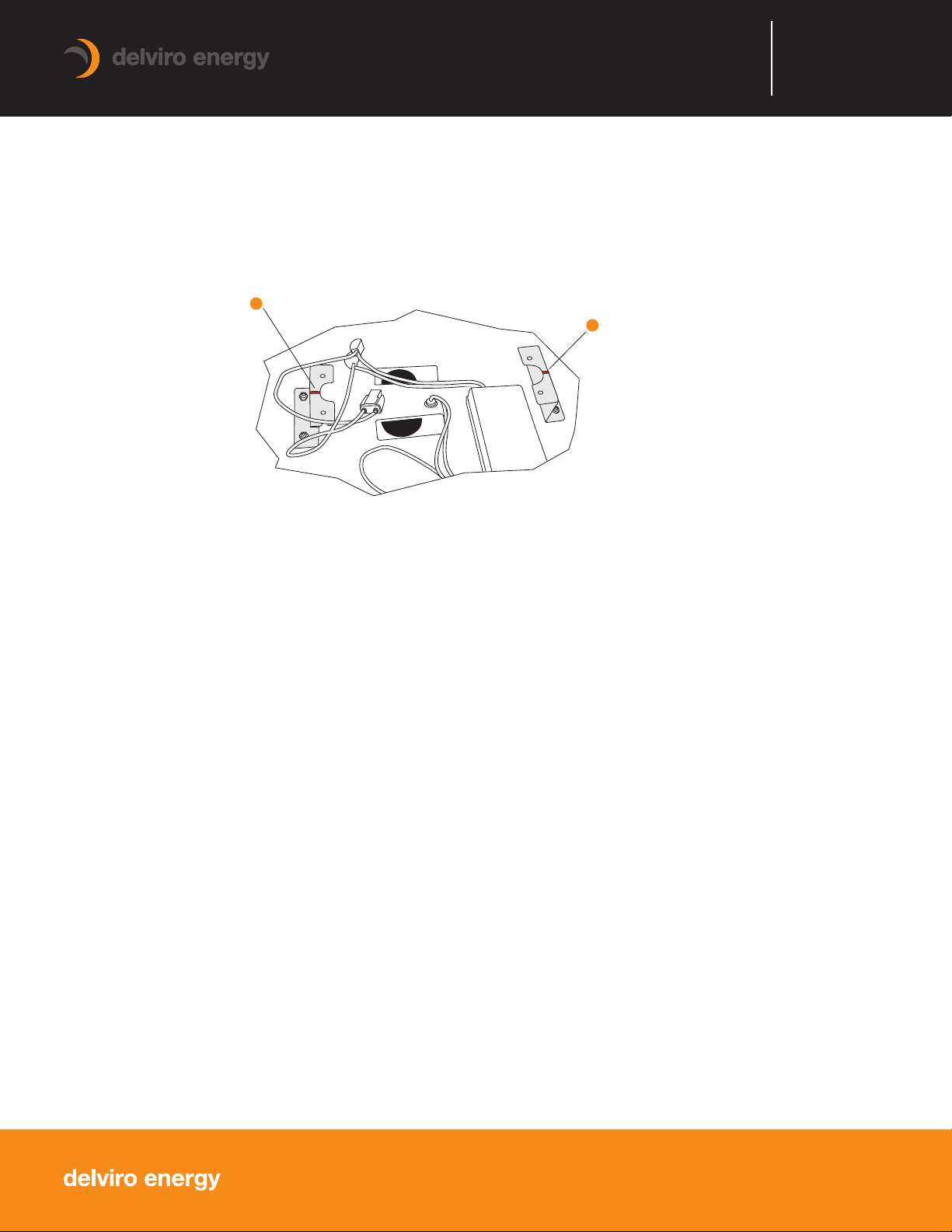
11. Take note of the red lines on the mounting angles (Fig. 11). Use the lines as a guide when placing the LED half moon
plates back into the fixture. First connect the orange luminaire disconnect together - should like (Fig. 9).
12. Orient the LED panels in such a manner that the UPPER LED plate lines up with the UPPER area on the fixture body (Fig. 7). and the LOWER LED
plate lines up with the LOWER area (Fig. 8). One should see that 3 holes will become visible that will be used to fasten the LED plates to the fixture
body on each half. Check by hand and make sure that the plates are snug in place.
13. Use the black head screws with nylon washer and fasten the 6 screws respectively into place (see Fig. 3, 4, and 5).
It might be easier to first fasten the 4 middle holes then the 2 remaining further holes after.
14. Check for loose wire or connections and turn on the power to ensure the light functions prior to placing the lens in
the fixture.
15. Turn off the power and slide the provided lens through the front opening. The lens might have to be held in a curved
position to get through the opening. Ensure the plastic removable side stays towards the fixture opening (outside).
16. Once the lens is in place remove the plastic from the front side plastic - the lens should be shiny.
17. Turn on the power to test the light and proceed with the next light installation.
LOWER
UPPER
Red lines to help installer line
up panels for assembly
Red lines to help installer line
up panels for assembly
Fig. 11
Table of contents
Popular Light Fixture manuals by other brands


Claypaky
Claypaky C61725 instruction manual

JB Systems Light
JB Systems Light B04707 Operation manual

Southco
Southco EM-10-1X-410 Series operating instructions

FormaLighting
FormaLighting POLARIS 20 Installation instruction

HAMPTON BAY
HAMPTON BAY 18020 Installation instruction

Delta Light
Delta Light 6 202 0142 74 31 Installation instruction