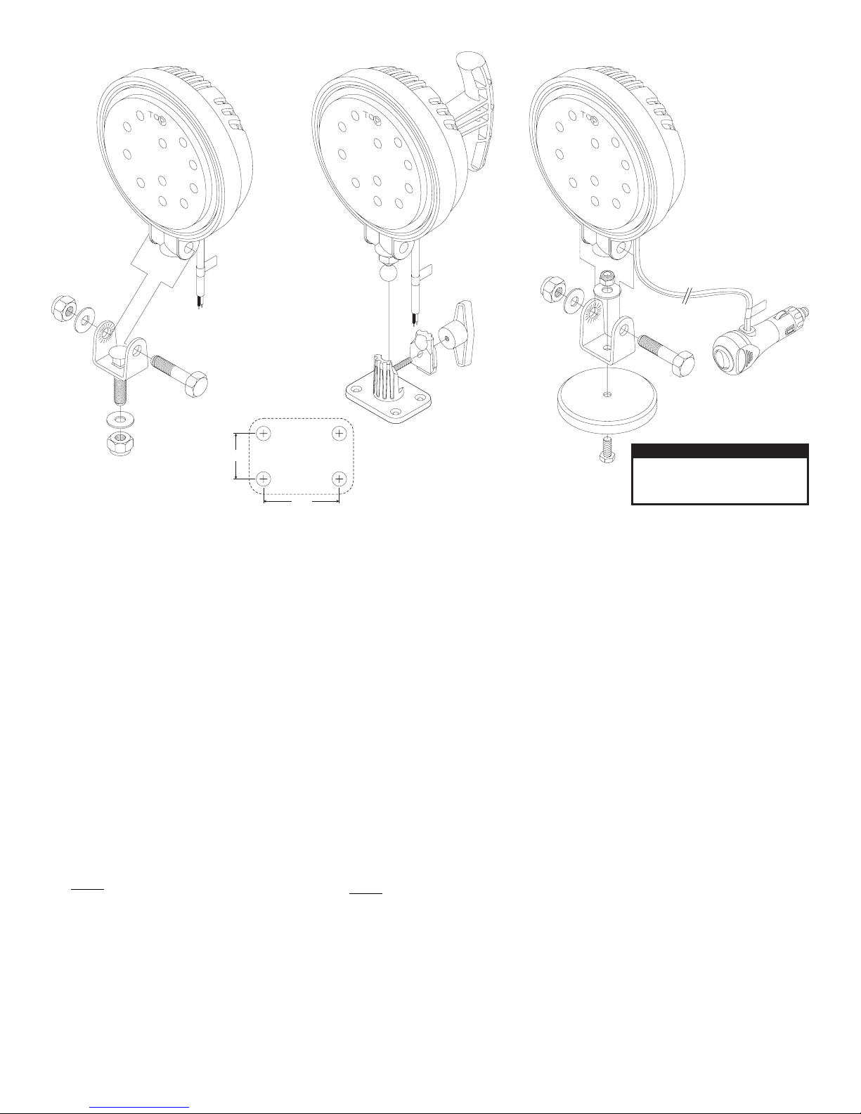
Whelen Engineering Company PAR36 Super-LED User manual
Other Whelen Engineering Company Light Fixture manuals

Whelen Engineering Company
Whelen Engineering Company 600-series User manual

Whelen Engineering Company
Whelen Engineering Company Inner Edge Interior Series User manual

Whelen Engineering Company
Whelen Engineering Company LFL Liberty Mini Edge User manual

Whelen Engineering Company
Whelen Engineering Company Inner Edge FST WeCan User manual

Whelen Engineering Company
Whelen Engineering Company Responder R2HD Series User manual

Whelen Engineering Company
Whelen Engineering Company Liberty WeCan Duo-Color User manual

Whelen Engineering Company
Whelen Engineering Company 45FL Series User manual

Whelen Engineering Company
Whelen Engineering Company Freedom II WeCan User manual

Whelen Engineering Company
Whelen Engineering Company Delta Independence User manual

Whelen Engineering Company
Whelen Engineering Company Responder R9HD Series User manual

Whelen Engineering Company
Whelen Engineering Company Safety Site User manual

Whelen Engineering Company
Whelen Engineering Company TIR3 User manual

Whelen Engineering Company
Whelen Engineering Company Freedom Mini Edge User manual

Whelen Engineering Company
Whelen Engineering Company LFL Liberty LC 2010 User manual
Popular Light Fixture manuals by other brands

Emos
Emos CLASSIC ZY1431T manual

Westinghouse
Westinghouse Outdoor Lighting Fixture owner's manual

Hedler
Hedler C 12 silent Operation manual

Blizzard Lighting
Blizzard Lighting Puck: CSI manual

Energetic Lighting
Energetic Lighting ELYSL-5004 Series installation instructions

Lightmaxx
Lightmaxx Shaft 5R user manual


Cooper Lighting
Cooper Lighting Halo L3232E Specification sheet

Stageline
Stageline ODW-2410RGBW instruction manual

Light Sky
Light Sky Tornado Series user manual

Lightolier
Lightolier Paralyte 2424 PLA2G9LS26U specification

Lightolier
Lightolier Lytespan 83ED17S specification

Lightolier
Lightolier Calculite CS8226 specification