EM-10 E-Keeper latch System
Operating Instructions
Applicable models
EM-10-1X-410 Series front mount latch bolt
EM-10-2X-410 Series side mount latch bolt
EM-10-3X-410 Series side mount latch bolt
EM-10-4X-410 Series dead bolt latch bolt
Electrical specifications and requirements:
To operate the latch, it must be properly connected or wired for
power, control, and optional feedback signal. An external 12VDC
power supply is required to power the latch. The power supply should
be sized to provide sufficient current for your application or a
minimum of 1.5 Amps per latch.
Power:
Voltage required: 12-24 VDC (9 to 26V)
Typical Operating current: 200mA
Typical Operating transit time: less than 1 second
Max current (stalled latch): 1A Max @12VDC
Standby current: less than 200µA, plus output signal current if
applicable. Power must be present during transit times. The latch will
maintain either position if power is removed (fails neutral)
Control Input Signal: is required to control the latch bolt position
either extended or retracted. The control signal can be changed
simply by using a low current switch as wired in the diagram above.
The control signal current draw is less than 1mA.
- For RETRACTED position: supply 12-24 VDC (9 to 26V) for a
minimum of 50 Milliseconds. The latch bolt will remain retracted
for as long as the signal is present or a minimum programmed
time of 1 second.
- For EXTENDED position: supply open contact or 0VDC(0 to .5V)
Note:
1. On power up, there is a 870mS delay before the control signal is active.
2. Once the latch bolt extends, there is an 85mS delay before the
control signal is active again.
Output signal: is a signal that can be used if desired as feedback to
monitor the position of the latch or error mode.
- The output is an open collector output. The maximum load
applied must be less than 450mA.
CAUTION! To avoid damage to the product do not exceed the
maximum output signal load of 450mA and carefully use the correct
polarity shown.
-Output will turn ON when latch bolt is in retracted position. NOTE:
External compression of the latch bolt will not produce any output signal.
-Output will slowly flash ON/OFF when a latch error occurs.
The latch error function is a timer that monitors the transit time of the
latch when traveling between the EXTENDED or RETRACTED
position. The latch will try to reach the new position for two attempts. If
the latch does not reach the new position the latch will enter error
mode and flash the output to indicate that there is a problem. The error
mode is a passive error indicator only and will reset when a new
change in position is commanded.
The latch will go into error mode:
-if there is too much load, or there is an obstruction preventing
the retracting movement of the latch bolt.
-if the output gear is missing or if there is internal damage to the latch.
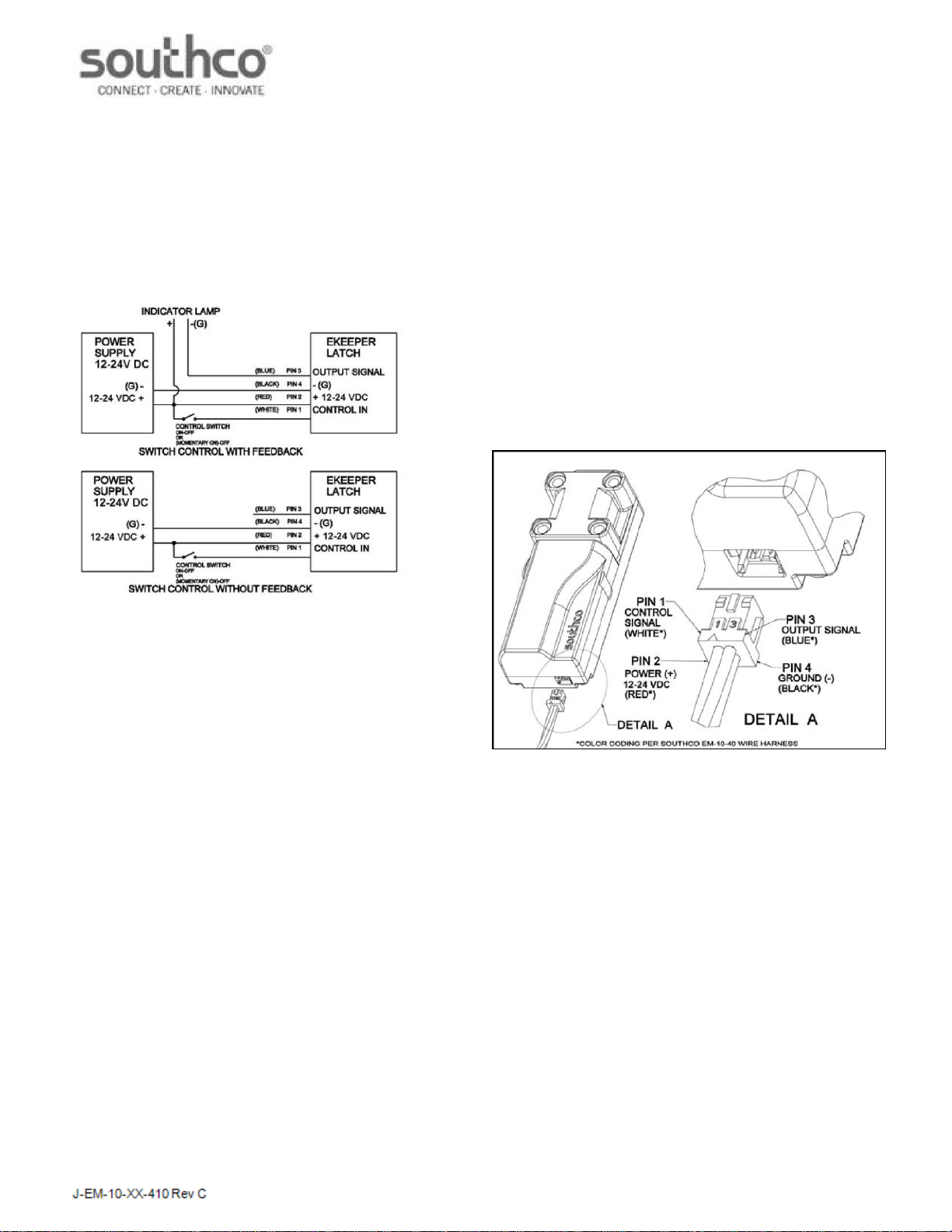
Electrical connections:
The latch is equipped with the following four position connector:
Hirose Electric Co. Ltd Part Number: DF11-4DP-2DS
Pin 1: Control Input signal
Pin 2: Power (+)
Pin 3: Output signal
Pin 4: Ground (-)
Mate connector required (Not Included)
Hirose Electric Co. Ltd
Part Number: DF11-4DS-2C crimp socket
Part Number:DF11-series crimping contact for
socket 24 AWG wire minimum recommended.
OR
Order Southco part Number: EM-10-4X for mate connector with
three wire length options. The Mate connector is polarized and
should be inserted as shown. Note the markings to indicate the
positions.
Mounting:
The latch should be mounted to a rigid and flat surface using four #6 or
M4 machine screws of appropriate length for your application (screws
not supplied). For additional product dimension see the customer
drawing specific to your model available from www.southco.com
CAUTION! The mounting fasteners also serve to permanently secure
the latch bolt housing to the base. Do not operate the latch without
mounting fasteners to secure the latch housing. The latch bolt has
approximately 8mm of travel and will fully retract into the latch bolt
housing.
For EM-10-1X-410, EM-10-2X-410 AND EM-10-3X-410 ONLY
When in the EXTENDED position the latch bolt is spring loaded and
can be retracted manually by applying an external force. This
functionality allows it to be used as a "push-to-close" latch.
For EM-10-4X-410 ONLY
Do not obstruct the motion of the dead bolt. Ensure that the dead bolt
is free to travel to its fully extended position. The dead bolt is not
spring loaded. Blocking the dead bolt will stall the drive motor and
may reduce the life of the product.
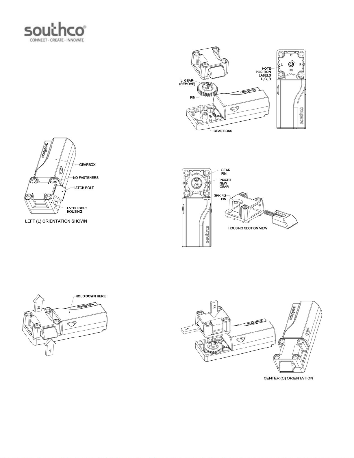
The E-keeper product is intended to be used with either a fixed strike
or a secondary mechanical latch. For installation recommendations
or support please contact customer service. The orientation of the
latch bolt can be changed from the factory position to Left, Center or,
Right positions, but does require additional parts to do so. Order
latch bolt rotation kit Southco part number EM-10-32-85 to change to
left center or right orientation.