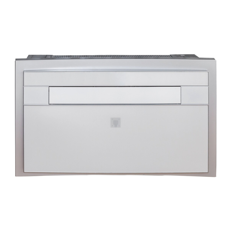
DencoHappel ZGF.1E series User manual

OPERATION MANUAL
Decentral Systems Comfort - Fan Coil Units
Flex-Geko®
Flexible Solutions for all Demands

Table of Contents Flex-Geko Fan Coil Unit
2PR-2011-0115-GB • Subject to modifications • R4-12/2015
1 Safety and User Instructions . . . . . . . . . . . . . . . . . . . . . . . . . . . . . . . . . . .5
1.1 Symbols used . . . . . . . . . . . . . . . . . . . . . . . . . . . . . . . . . . . . . . . . . . . . . . .5
1.2 Safety instructions: warning and danger symbols . . . . . . . . . . . . . . . . . . . .5
1.3 Safety-conscious work procedures . . . . . . . . . . . . . . . . . . . . . . . . . . . . . . .6
1.4 Personnel selection and qualification . . . . . . . . . . . . . . . . . . . . . . . . . . . . .7
1.5 Proper use . . . . . . . . . . . . . . . . . . . . . . . . . . . . . . . . . . . . . . . . . . . . . . . . . .7
1.6 Improper use . . . . . . . . . . . . . . . . . . . . . . . . . . . . . . . . . . . . . . . . . . . . . . . .9
1.7 Safety regulations and codes . . . . . . . . . . . . . . . . . . . . . . . . . . . . . . . . . . .9
1.8 Modifications and changes . . . . . . . . . . . . . . . . . . . . . . . . . . . . . . . . . . . . .9
1.9 Spare parts . . . . . . . . . . . . . . . . . . . . . . . . . . . . . . . . . . . . . . . . . . . . . . . . .9
1.10 Selection and qualification of personnel . . . . . . . . . . . . . . . . . . . . . . . . . .9
2 Technical Description . . . . . . . . . . . . . . . . . . . . . . . . . . . . . . . . . . . . . . . .10
2.1 Components of the unit . . . . . . . . . . . . . . . . . . . . . . . . . . . . . . . . . . . . . . . .10
2.2 Material specification . . . . . . . . . . . . . . . . . . . . . . . . . . . . . . . . . . . . . . . . . .12
2.3 Range of Application . . . . . . . . . . . . . . . . . . . . . . . . . . . . . . . . . . . . . . . . . .13
2.3.1 Dimension . . . . . . . . . . . . . . . . . . . . . . . . . . . . . . . . . . . . . . . . . . . . .17
2.4 Unit data . . . . . . . . . . . . . . . . . . . . . . . . . . . . . . . . . . . . . . . . . . . . . . . . . . .19
2.4.1 Condensate pump . . . . . . . . . . . . . . . . . . . . . . . . . . . . . . . . . . . . . . .23
2.4.2 Air side accessories . . . . . . . . . . . . . . . . . . . . . . . . . . . . . . . . . . . . . .25
3 Shipping and Storage . . . . . . . . . . . . . . . . . . . . . . . . . . . . . . . . . . . . . . . . .26
3.1 Transport safety . . . . . . . . . . . . . . . . . . . . . . . . . . . . . . . . . . . . . . . . . . . . . .26
3.2 Packaged content . . . . . . . . . . . . . . . . . . . . . . . . . . . . . . . . . . . . . . . . . . . .26
3.3 Packaging . . . . . . . . . . . . . . . . . . . . . . . . . . . . . . . . . . . . . . . . . . . . . . . . . .26
3.4 Shipping . . . . . . . . . . . . . . . . . . . . . . . . . . . . . . . . . . . . . . . . . . . . . . . . . . . .26
3.5 Temporary storage . . . . . . . . . . . . . . . . . . . . . . . . . . . . . . . . . . . . . . . . . . .28
3.6 Disposal . . . . . . . . . . . . . . . . . . . . . . . . . . . . . . . . . . . . . . . . . . . . . . . . . . . .28
4 Assembly . . . . . . . . . . . . . . . . . . . . . . . . . . . . . . . . . . . . . . . . . . . . . . . . . . .29
4.1 Installation site . . . . . . . . . . . . . . . . . . . . . . . . . . . . . . . . . . . . . . . . . . . . . . .29
4.1.1 Recommended service opening for maintenance work on the
basic unit . . . . . . . . . . . . . . . . . . . . . . . . . . . . . . . . . . . . . . . . . . . . . . . . . . . . . . .30
4.1.2 Removing unit casing . . . . . . . . . . . . . . . . . . . . . . . . . . . . . . . . . . . .31
4.1.3 Pre-installation work . . . . . . . . . . . . . . . . . . . . . . . . . . . . . . . . . . . . .32
4.2 Unit mounting . . . . . . . . . . . . . . . . . . . . . . . . . . . . . . . . . . . . . . . . . . . . . . . .33
4.3 Installing mixed-air units on the wall with fresh air intake from the rear . . .36
4.3.1 Installing stand-alone mixed-air units on the wall with fresh air
intake from the rear . . . . . . . . . . . . . . . . . . . . . . . . . . . . . . . . . . . . . . . . . . . . . . .38
4.3.2 Installing mixed-air units on the ceiling with fresh air intake from
above (vertical) . . . . . . . . . . . . . . . . . . . . . . . . . . . . . . . . . . . . . . . . . . . . . . . . . .39
4.4 Installing mixed-air units on the ceiling with fresh air intake
from rear (horizontal) . . . . . . . . . . . . . . . . . . . . . . . . . . . . . . . . . . . . . . . . . . . . .39

Flex-Geko Fan Coil Unit Table of Contents
PR-2011-0115-GB • Subject to modifications • R4-12/2015 3
4.5 Setting mixed-air rate . . . . . . . . . . . . . . . . . . . . . . . . . . . . . . . . . . . . . . . . .40
4.6 Installing unit casing . . . . . . . . . . . . . . . . . . . . . . . . . . . . . . . . . . . . . . . . . .41
4.7 Mounting field-provided ductwork . . . . . . . . . . . . . . . . . . . . . . . . . . . . . . . .43
5 Hydraulic Connection . . . . . . . . . . . . . . . . . . . . . . . . . . . . . . . . . . . . . . . . .45
5.1 General . . . . . . . . . . . . . . . . . . . . . . . . . . . . . . . . . . . . . . . . . . . . . . . . . . . .45
5.1.1 Overview of valves . . . . . . . . . . . . . . . . . . . . . . . . . . . . . . . . . . . . . .46
5.1.2 Heating and cooling connections for units without valves or with
on-site valves provided by others . . . . . . . . . . . . . . . . . . . . . . . . . . . . . . . . . . . .49
5.1.3 Heating and cooling connections for units with factory mounted
valves . . . . . . . . . . . . . . . . . . . . . . . . . . . . . . . . . . . . . . . . . . . . . . . . . . . . . . . . .50
5.1.4 Coil connections with units fitted with DX evaporator (refrigerant) . .53
5.1.5 Connecting condensate drain . . . . . . . . . . . . . . . . . . . . . . . . . . . . . .58
5.2 Connecting condensate pump . . . . . . . . . . . . . . . . . . . . . . . . . . . . . . . . . .59
6 Electrical Connection . . . . . . . . . . . . . . . . . . . . . . . . . . . . . . . . . . . . . . . . .62
6.1 Connection diagrams . . . . . . . . . . . . . . . . . . . . . . . . . . . . . . . . . . . . . . . . .62
6.2 Terminal box or electrical control box . . . . . . . . . . . . . . . . . . . . . . . . . . . . .62
6.3 Fan Speed . . . . . . . . . . . . . . . . . . . . . . . . . . . . . . . . . . . . . . . . . . . . . . . . .63
6.4 Connection with controls by others . . . . . . . . . . . . . . . . . . . . . . . . . . . . . . .67
6.4.1 Overview of DencoHappel MATRIX control electronics . . . . . . . . . .71
6.4.2 Mounting control panel . . . . . . . . . . . . . . . . . . . . . . . . . . . . . . . . . . .72
6.4.3 Electrical connection with MATRIX . . . . . . . . . . . . . . . . . . . . . . . . . .76
6.4.4 Network and shield connection MATRIX.Net (not for MATRIX 500) . 87
6.4.5 Electrical connection of DencoHappel miniature switches/relay PCB
for units with AC fans . . . . . . . . . . . . . . . . . . . . . . . . . . . . . . . . . . . . . . . . . . . . .95
6.5 Connecting miniature switches CMS and CMT . . . . . . . . . . . . . . . . . . . . . .96
6.6 Connecting miniature switches CET . . . . . . . . . . . . . . . . . . . . . . . . . . . . . .98

Table of Contents Flex-Geko Fan Coil Unit
4PR-2011-0115-GB • Subject to modifications • R4-12/2015
7 Commissioning . . . . . . . . . . . . . . . . . . . . . . . . . . . . . . . . . . . . . . . . . . . . . .104
7.1 Safety check . . . . . . . . . . . . . . . . . . . . . . . . . . . . . . . . . . . . . . . . . . . . . . . .104
7.2 Checking the control and shut-off valves . . . . . . . . . . . . . . . . . . . . . . . . . . .105
7.2.1 Vent the unit . . . . . . . . . . . . . . . . . . . . . . . . . . . . . . . . . . . . . . . . . . . .110
7.2.2 Checking the condensate drain . . . . . . . . . . . . . . . . . . . . . . . . . . . . .111
7.3 Terminating resistors . . . . . . . . . . . . . . . . . . . . . . . . . . . . . . . . . . . . . . . . . .112
7.3.1 Setting address . . . . . . . . . . . . . . . . . . . . . . . . . . . . . . . . . . . . . . . . .114
7.4 Setting limitation functions . . . . . . . . . . . . . . . . . . . . . . . . . . . . . . . . . . . . . .116
7.4.1 Switch on unit . . . . . . . . . . . . . . . . . . . . . . . . . . . . . . . . . . . . . . . . . .118
7.4.2 Checking data connection . . . . . . . . . . . . . . . . . . . . . . . . . . . . . . . . .119
7.4.3 Checking control inputs and outputs . . . . . . . . . . . . . . . . . . . . . . . . .120
7.5 Checking electric heater (only or units with electric heating) . . . . . . . . . . . .121
7.5.1 Checking frost protection (only with mixed-air units) . . . . . . . . . . . . .122
7.6 Checking condensate pump (applies only to cooling units
with condensate pump) . . . . . . . . . . . . . . . . . . . . . . . . . . . . . . . . . . . . . . . . . . . .122
7.6.1 DencoHappel MATRIX functions . . . . . . . . . . . . . . . . . . . . . . . . . . . .124
8 Maintenance and Troubleshooting . . . . . . . . . . . . . . . . . . . . . . . . . . . . . .127
8.1 Maintenance . . . . . . . . . . . . . . . . . . . . . . . . . . . . . . . . . . . . . . . . . . . . . . . .127
8.1.1 Quarterly maintenance . . . . . . . . . . . . . . . . . . . . . . . . . . . . . . . . . . .129
8.1.2 Semi-annual maintenance . . . . . . . . . . . . . . . . . . . . . . . . . . . . . . . . .130
8.1.3 Annual maintenance . . . . . . . . . . . . . . . . . . . . . . . . . . . . . . . . . . . . .132
8.1.4 Before cooling season . . . . . . . . . . . . . . . . . . . . . . . . . . . . . . . . . . . .138
8.2 Before heating season . . . . . . . . . . . . . . . . . . . . . . . . . . . . . . . . . . . . . . . . .139
8.2.1 Break-downs . . . . . . . . . . . . . . . . . . . . . . . . . . . . . . . . . . . . . . . . . . .139
8.3 Troubleshooting . . . . . . . . . . . . . . . . . . . . . . . . . . . . . . . . . . . . . . . . . . . . . .141
9 Declaration of conformity . . . . . . . . . . . . . . . . . . . . . . . . . . . . . . . . . . . . . .146

Flex-Geko Fan Coil Unit Safety and User Instructions
PR-2011-0115-GB • Subject to modifications • R4-12/2015 5
1 Safety and User Instructions
This is an original operation manual verified by the manufacturer.
Flex-Geko fan coil units are developed and manufactured in accordance with the
state-of-the-art technological standards, established technical safety codes and
EC Directive on Machinery.
The Flex-Geko fancoil unitsare reliable in operation and satisfystrictqualitystan-
dards. Future-oriented technology and pronounced operator and maintenance
friendliness were combined in this product series.
Nevertheless, all fan coil units could pose unavoidable residual risk of injury or
risk of equipment or property-damage only accidents. Therefore your personal
safety and the proper operation of the unitdepend on the strict observance of the
safety instructions. Failure to follow the safety precautions could result in death,
serious injury, environmental damage and/or considerable property damage.
Observing the safety instructions in the current operation manual will help avoid
the risks, ensure economical operation of the unit and let you enjoy the full bene-
fits of the product. The safety aspects covered by this chapter are valid for the
entire operation manual.
1.1 Symbols used
The following symbols are used to highlight particular text sections:
–This symbol is used to indicate lists.
•This symbol indicates handling instructions.
9This symbol indicates the result of an action.
1.2 Safety instructions: warning and danger symbols
Allinformationinthischapter is importantand relevantfor your safety.That is why
not all of the information contained in the present chapter is labelled with special
danger pictograms.
In subsequent chapters of this manual, warning notes are indicated by picto-
grams. General safety instructions are listed at the beginning of the respective
chapter and special safety instructions on specific jobs are listed along with the
respective steps. The following warnings are used:
USER INSTRUCTIONS
User instructions provide optimal, efficient and environmentally friendly meth-
ods for using and handling the units.
RECYCLING
This symbol is used to highlight instructions on proper reuse of packaging ma-
terial and disused components (separated according to recyclable materials,
e.g. metal, plastic, etc.).

Safety and User Instructions Flex-Geko Fan Coil Unit
6PR-2011-0115-GB • Subject to modifications • R4-12/2015
1.3 Safety-conscious work procedures
To ensure your own safety consider the following safety instructions:
HAZARDOUS VOLTAGE!
This symbol indicates a risk of electrical shock that can result in serious injury,
death and material damage.
DANGER OF SCALDING!
This symbol indicates a risk of scalding through running hot liquids that can
result in personal injury including death and material damage.
WARNING: RISK OF ROTATING COMPONENTS!
This symbol indicates a hazardous location with a risk of personal injury includ-
ing death and material damage.This symbol indicates a hazardous location
with a risk of personal injury including death and material damage.
DANGER DUE TO OVERHEAD LOADS!
This symbol indicates a hazardous location with a risk of personal injury includ-
ing death and material damage.This symbol indicates a hazardous location
with a risk of personal injury including death and material damage.
PERSONAL INJURY!
This symbol indicates (different from the above-mentioned danger types) a
hazardous location with a risk of personal injury including death and material
damage.
DAMAGE TO THE UNIT!
This symbol indicates a hazardous location with a risk of material damage that
can also lead to personal injury.
ENVIRONMENTAL DAMAGE!
This symbol warns about damage to the environment.
HAZARDOUS VOLTAGE!
Before carrying out any jobs on the unit, power the unit down to prevent injury
from electrical current. Ensure that the unit is secured against being energised
again at an appropriate point of the on-site power supply.
DANGER OF SCALDING!
Before performing work on the valves or the inlet or outlet pipes, seal off the
heating or cooling medium inlet to prevent scalding. Commence work only after
the heating medium has cooled down.
WARNING: RISK OF ROTATING COMPONENTS!
The rotating fanwheel poses a risk of injury!Beforeperformingany work on the
unit, ensure that the unit is de-energized. Ensure that the unit is secured
against being switched on again at an appropriate point of the on-site power
supply.

Flex-Geko Fan Coil Unit Safety and User Instructions
PR-2011-0115-GB • Subject to modifications • R4-12/2015 7
The following accident prevention regulations apply (VBG1, BGV A2 (previously:
VBG4), VBG7w, VBG9a) and generally recognized codes for machinery and prin-
ciples of engineering, particularly DIN VDE 0100, DIN VDE 0105.
1.4 Personnel selection and qualification
The unit may be installed, operated and maintained only by qualified, specially
trained and authorized staff. The following tasks described in the operation man-
ual may only be performed by qualified personnel:
–Shipping and storage
–Assembly
–Hydraulic Connection
–Electrical connection
–Commissioning
–Maintenance
1.4.1 Chiller
Units that are equipped witha direct evaporator are considered as a refrigeration
system in technical terms.
1.5 Proper use
Fan coil units of the Flex-Geko series are exclusively designed for ventilating,
heating, filtering and cooling purposes. As medium water, water/glycol solution
(max. 50 %) or different refrigerants (direct evaporator) may be used.
DANGER DUE TO OVERHEAD LOADS!
Wear a helmet and safety boots to prevent injury from falling components,
especially when fitting the unit to the ceiling. Ceiling installations should always
be performed by two persons.
PERSONAL INJURY!
Always wear protective gloves when shipping or installing the unit to prevent
injury caused by sharp edges.
PERSONAL INJURY!
Risk posed by a refrigeration unit:
Ensure that only specialised personnel can access the unit (e.g. refrigeration
engineer).
REFRIGERATION SYSTEM!
For all jobs on the direct evaporator ensure that all relevant codes and reg-
ulations like DIN norms, VDI guidelines, VDMA codes as well as country-spe-
cific accident prevention regulations are adhered to.
DAMAGE TO THE UNIT!
During the installation it must be ensured that no condensation or splash water
penetrates into electric units in case of unit/installation damage.

Safety and User Instructions Flex-Geko Fan Coil Unit
8PR-2011-0115-GB • Subject to modifications • R4-12/2015
The following limit values apply to medium for operating Cu/Al heat exchangers:
The Flex-Geko may only be operated indoors.
The Flex-Geko units are designed for wall and ceiling installation.
Parameter Unit Value
pH-value (at 20 °C) 7.5 - 9
Conductivity (at 20 °C) μS/cm < 700
Oxygen content O2mg/l < 0.1
Total hardness °dH 1 - 15
Dissolved sulphur S not detectable
Sodium Na+mg/l < 100
Iron Fe2+, Fe3+ mg/l < 0.1
Manganese Mn2+ mg/l < 0.05
Ammonium content NH4+mg/l < 0.1
Chloride Cl-mg/l < 100
Sulphate SO42- mg/l < 50
Nitrite NO2-mg/l < 50
Nitrate NO3-mg/l < 50
Tab. 1-1: Limit values for medium in closed heating and cooling circuits
EQUIPMENT DAMAGE!
In open systems (e.g. when using well water consider limit values from table
from Tab. 1-1), used water should additionally be cleansed of suspended mat-
ter using a filter to be installed at the inlet. Failure to do so could result in a risk
of erosion by suspended matter.
It must also be ensured that the unit is protected from dust and other sub-
stances that can cause acidic or alkaline reaction with water (aluminium corro-
sion).
It is not allowed to use Flex-Geko units, in particular with a cooling function, for
suction of kitchen exhaust air containing organic acids, e.g. vinegar. Besides, it
isnotallowedtousecleaningagents,containingvinegarorotherorganicacids,
to clean rooms where such units are installed due to a substantial risk of acid-
related corrosion of aluminium fins!
The unit is considered to be used inan improper manner if it is applied for other
purposes or a purpose that is not covered by the scope of the given operation
manual.The manufactureror supplier is notliablefor any resultingdamage:the
user alone bears the full risk.
The operator is responsible for proper use.
Proper use also stipulates the observance of the operation manual and the in-
spection and maintenance conditions defined by DencoHappel.

Flex-Geko Fan Coil Unit Safety and User Instructions
PR-2011-0115-GB • Subject to modifications • R4-12/2015 9
1.6 Improper use The Flex-Geko may not be operated:
–Outdoors
–In areas subject to explosion risk
–In wet areas
–In locations with high dust levels or aggressive air
–In open systems (e.g. well water) in combination with a supply line without a
filter
1.7 Safety regulations and codes
When carrying out installation, commissioning, maintenance and service of Flex-
Geko units, all local safety regulations and codes aswell as generally established
technical practices must be followed.
1.8 Modifications and changes
No changes, add-ons or modifications may be performed on the Flex-Geko air
treatment unit or its components.
Changes or modifications of the Flex-Geko unit will invalidate the CE conformity
and render all warranty claims null and void.
1.9 Spare parts
Only original DencoHappel spare parts are allowed, since DencoHappel is not lia-
ble if third-party spare parts are used.
1.10 Selection and qualification of personnel
PERSONAL INJURY AND EQUIPMENT DAMAGE!
Improper use can cause personal injury and material damage.
NOTICE!
It must be ensured that every person working on the Flex-Geko fan coil unit has read
and understood entire operation manual. Please read this document fully before
commencing any work, and not while performing a task.
Electrical and water connections must be established by qualified licensed staff or
other individuals with proper professional training and experience in the following
areas:
– Occupational health and safety regulations
– Relevant accident prevention regulations
– Directives and recognized codes of practice
All skilled staff must be able to assess the entrusted work and be able to recognize
and avoid all associated dangers.

Safety and User Instructions Flex-Geko Fan Coil Unit
10 PR-2011-0115-GB • Subject to modifications • R4-12/2015
2 Technical Description
2.1 Components of the unit
Fig. 2-1: Unit components (depending on unit model)
1: Holding plate
2: Heat Exchanger
3: Control panel
4: Metal sheet electric control box
5: Basic casing (rear wall with lateral sheet steel panels)
6: Cover sheet at discharge on front side
7: Bottom panel at intake on front side
8: Filter element
9: Main drain pan
10: Fan with casing
11: Suction side front panel at bottom/rear intake
12: Pressure side front panel with frontal discharge
13: Pressure side front panel with top/frontal discharge
14: Mixed-air box with actuator
15: Unit foot on left side for recirculating-air unit
16: Unit foot on right side for recirculating-air unit
17: Lateral ceiling drain pan
18: Lateral wall drain pan
19: Unit casing
20: Unit foot cover, left side
21: Unit foot cover, right side
22: Suction grille
23: Front casing for front side discharge
24: Front casing for front side intake
25: Front casing for front side intake and discharge

Flex-Geko Fan Coil Unit Safety and User Instructions
PR-2011-0115-GB • Subject to modifications • R4-12/2015 11
Various unit parts indicated in Fig. 2-1 are specified in detail as follows.
Holding plate (Pos. 1)
The mounting panel is used to support the heat exchanger.
Heat exchanger (Pos. 2)
The heat exchanger for chilled and warm water has a connection fitting with 1/2"
internal thread as well as air vents and drain valves. Depending on unit use, the
heat exchanger is equipped with two connection fittings (water inlet and outlet in
a 2-pipe system) or with four connection fittings (water inlet and outlet in a 4-pipe
system).
The heat exchanger is designed for operation with a refrigerant (DX evaporator)
and, depending on the unit size, is equipped with 10 mm or 16 mm solder fittings.
Control panel (Pos. 3)
A control panel is an optional component. If available and depending on the con-
figuration, the control panel is mounted on the unit or supplied separately.
Metal sheet electric control box (Pos. 4)
Depending on the unit model, the galvanized steel sheet electrical control box
contains the following components:
–One or more printed circuit board(s)
–Contactors/relays
–Terminal block(s).
Filter element (Pos. 8)
Filter element is available in filter class G1, G2 or G3 and consists of a filter mat
in a frame. G2 and G3 filters must be replaced, G1 filter can be cleaned.
Main drain pan(Pos. 9)
The main drain pan is used to collect condensate of Flex-Geko and serves as a
holding plate for one or more fans.
Fan with casing (Pos. 10)
The fan consists of one or more centrifugal impellers of a single and/or tandem
fan type. The centrifugal fans are equipped withlow-noise, maintenance-free ball
or sleeve bearings. The motors are performed and can be selected as stage
motors (AC) or continuously variable (EC motors), motor protection is ensured
through integrated (optional externally and lead out) thermal contacts or block-up
protection with an EC motor. These are performed in IP44 or IP32 protection type
and insulation class B.
NOTICE!
Depending on the configuration the unit can also be equipped with a terminal
box.

Safety and User Instructions Flex-Geko Fan Coil Unit
12 PR-2011-0115-GB • Subject to modifications • R4-12/2015
Unit foot cover, right/left (Pos. 20/Pos. 21)
Unit foot cover panels are used as a casing for unit feet (Pos. 15/Pos. 16) or
mixed-air box (Pos. 14) and are connected with the unit casing (Pos. 19).
Mixed-air box with actuator (Pos. 14)
Mixed-air box is fitted with leak-tight mixed-air dampers. The unit is equipped with
230 V~ damper actuator. No electrical current is required to close the mixing-air
damper. Mechanical limitation makes it possible to regulate outside air rate
between 37 % to 100 %.
Unit feet, right/left with recirculating-air units (Pos. 15/Pos. 16)
Unit feet automatically ensure the necessary clearance for unobstructed air flow
with ceiling installation.
Lateral ceiling or wall drain pan (Pos. 17, Pos.18)
The drain pan is used to collect condensate forming on valves and connection fit-
tings as well as for collecting condensate from main tray and draining it into exter-
nal line.
2.2 Material specification
Unit part Material
Holding plate Galvanized metal sheet
Basic casing Galvanized metal sheet with polyethylene thermal insulation
Heat Exchanger Copper/aluminium
Fan motor Different materials
Connecting cable Different materials
Fan with casing Galvanized metal sheet; plastic
Main drain pan Coatedmetalsheet withpolyethylenethermalinsulationontheunderside,
plastic drain pipework
Switch box with control electronics Different materials
Filter element Filter fleece, synthetic
Discharge grille Aluminium, plastic
Foot cover panels Galvanized and powder-coated metal sheet; plastic
Unit casing Front panel made of galvanized and powder coated or coated sheet steel;
plastic service panels and lateral components
Suction grille Galvanized coated metal sheet
Mixed-air box Different materials
Lateral ceiling drain pan Plastic
Lateral wall drain pan Plastic
Actuator mixed-air Different materials
Mixing-air damper and separating
web Aluminum
Electric heating rods with cable Stainless steel fins and pipe. The cable is made of different materials.
Tab. 2-1: Material specification of unit components

Flex-Geko Fan Coil Unit Safety and User Instructions
PR-2011-0115-GB • Subject to modifications • R4-12/2015 13
2.3 Range of Application
2.3.1 Medium inlet temperature
To prevent condensate from forming on non-insulated casing parts when the tem-
perature falls below the dew point during cooling operation, certain minimum
water inlet temperature or evaporating temperature must be maintained. These
temperatures depend on ambient temperature and indoor relative humidity and
are specified in the following diagram.
Example
The room temperature amounts to 28°C, the relative humidity is 60%. According
to the diagram (Fig. 2-2) the minimum allowed water inlet temperature amounts
to 8°C.
2.3.2 External air side resistance
Fig. 2-2: Minimum allowed medium inlet temperature or evaporating temperature (refrigerant) as a function of
indoor air condition; air pressure = 1013 hPa; ϕ= relative humidity
Medium inlet temperature or evaporating temperature in °C
Room temperature in °C
NOTICE!
If the fan coil unit is operated in a system that generates air side resistance (ex-
ternalpressure),the lattershouldbe dimensionedinsuchaway thatthe airflow
of the fan coil unit is not reduced below 40 % of the nominal air volume flow at
the respective fan speed (refer to Table 2-12 on page 20).
PERSONAL INJURY!
On units with an electrical heater external pressure drop is not allowed!

Safety and User Instructions Flex-Geko Fan Coil Unit
14 PR-2011-0115-GB • Subject to modifications • R4-12/2015
2.3.3 Unit and heat exchanger
Unit and heat exchanger Values
Max. operating pressure/temperature 1.6 MPa (16 bar)/90 °C
Max. allowed ambient temperature 40 °C
Min. allowed ambient temperature 2 °C
Operating voltage 230 V AC, 50 Hz
Power consumption/protection class Refer to identification plate
Max. discharge temperature 75 °C (fire hazard)
Tab. 2-2: Operating limits for unit and heat exchanger
Model
size Capacity
size Maximum medium flow rate [l/h]
2-pipe
cooling or heating circuit 4-pipe
cooling circuit heating circuit
1
1
2
3
4
380
760
760
380
380
760
380
–
380
380
380
–
2
1
2
3
4
380
760
1140
380
760
760
380
–
380
380
380
–
3
1
2
3
4
760
1140
1140
760
760
1140
380
–
380
380
380
–
4
1
2
3
4
760
1140
1521
760
760
1140
760
–
380
380
380
–
5
1
2
3
4
760
1140
1521
760
1140
1140
760
–
380
380
380
–
6
1
2
3
4
1521
2281
3041
1140
1140
2281
760
–
380
380
380
–
7
1
2
3
4
1521
2281
3041
1140
1140
2281
760
–
380
380
380
–
8
1
2
3
4
1521
2281
3041
1521
1140
2281
760
–
380
380
380
–
Tab. 2-3: Maximum allowed medium flow rate

Flex-Geko Fan Coil Unit Safety and User Instructions
PR-2011-0115-GB • Subject to modifications • R4-12/2015 15
2.3.4 Valves with modulating actuators
2.3.5 Valves with thermoelectric actuators
Valves with modulating actuators Values
230 V/24 V 230 V 24 V
Max. operating pressure/inlet temperature 1.6 MPa (16 bar)/110 °C
Max. allowed ambient temperature 60 °C
Operating voltage 230 V AC
50/60 Hz 24 V AC
50/60 Hz
Power consumption/protection class 7 VA/IP43 0.7 VA/IP43
Running time 120 s (50 Hz)
100 s (60 Hz) 150 s (50 Hz)
125 s (60 Hz)
Water max. 50 % glycol concentration
Tab. 2-4: Operating limits for valves with modulating actuators
Valves with modulating actuators 230 V
and 2 floating auxiliary switches Values
Max. operating pressure/inlet temperature 1.6 MPa (16 bar)/110 °C
Max. allowed ambient temperature 60 °C
Operating voltage 230 V AC, 50/60 Hz
Power consumption/protection class 7 VA/IP43
Running time 150 s (50 Hz); 125 s (60 Hz)
Load capacity for auxiliary switch max. 5 (1) A/250 V
max. 100 mA/24 V
Water max. 50 % glycol concentration
Tab. 2-5: Operating limits for valves with modulating actuators and auxiliary
switches
Valves with thermoelectric actuators Values
230 V/24 V 230 V 24 V
Max. operating pressure/inlet temperature 1.6 MPa (16 bar)/110 °C
Max. allowed ambient temperature 50 °C
Operating voltage 230 V AC
50/60 Hz 24 V AC
50/60 Hz
Power consumption/protection class 3 VA/IP43
Running time approx. 180 s approx. 180 s
Water max. 50 % glycol concentration
Tab. 2-6: Operating limits for valves with thermoelectric actuators

Safety and User Instructions Flex-Geko Fan Coil Unit
16 PR-2011-0115-GB • Subject to modifications • R4-12/2015
2.3.6 Valves with continuous actuators
2.3.7 Thermostatic expansion valves
Valves with continuous actuators Values
Max. operating pressure/inlet temperature 1.6 MPa (16 bar)/110 °C
Max. allowed ambient temperature 55 °C
Operating voltage 24 V AC, 50/60 Hz
Analog control signal 0 ... 10 (2 ... 10) V
Power consumption/protection class 1.4 VA/IP40
Running time 150 s (50 Hz); 100 s (60 Hz)
Water max. 50 % glycol concentration
Tab. 2-7: Operating limits for valves with continuous actuators
Thermostatic expansion valves with ex-
ternal pressure equalisation Values
Allowed refrigerant groups R410A
Max. test pressure 32 bar
Max. suction pressure 29 bar
Max. ambient temperature 100 °C
Max. sensor temperature 140 °C
Allowed temperature range for evaporation + 15 °C to - 50 °C
Capillary tube length 1.5 m
Casing/membrane head material Brass/stainless steel
Tab. 2-8: Operating limits for thermostatic expansion valves

Flex-Geko Fan Coil Unit Safety and User Instructions
PR-2011-0115-GB • Subject to modifications • R4-12/2015 17
2.4 Dimension
2.4.1 Basic unit
Pos. 1: Basic unit
Pos. 2: Metal sheet electric control box
Pos. 3: Lateral wall drain pan
Pos. 4: Lateral ceiling drain pan
Fig. 2-3: Dimensions of basic unit (wall unit)
Fig. 2-4: Dimensions of basic unit (ceiling unit)
Model size 12345678
Width w [mm] 410 560 710 860 1010 1160 1310 1460
Tab. 2-9: Width of basic unit, depending on unit size
* Space need for field-provided piping on site
** only with frontal air intake
*** possibly additional space need of 5 mm (unit height)
with cooling units for pitched mounting
for condensate connection side
* Space need for field-provided piping on site
** only with frontal air intake
*** possibly additional space need of 5 mm (unit height)
with cooling units for pitched mounting
for condensate connection side

Safety and User Instructions Flex-Geko Fan Coil Unit
18 PR-2011-0115-GB • Subject to modifications • R4-12/2015
2.4.2 Unit casing
Pos. 1: Air intake grille (opt.)
Pos. 2: Discharge grille (opt.)
Relevant for the following casing types:
Comfort Economy
ZGF.1Cxx# ZGF.1Exx#
ZGF.2Cxx# ZGF.2Exx#
ZGF.3Cxx# ZGF.3Exx#
ZGF.4Cxx# ZGF.4Exx#
ZGF.5Cxx# ZGF.5Exx#
ZGF.6Cxx# ZGF.6Exx#
ZGF.7Cxx# ZGF.7Exx#
ZGF.8Cxx# ZGF.8Exx#
Casing variant:
xx = 01, 02, 03, 04, 05, 06, 07, 08, 13, 23
Discharge grille:
# = 1, 2, 3
Fig. 2-5: Dimension of casing
Casing design 01, 02, 03, 04, 13, 23
Casing design 05, 06
Casing design 07, 08
Modelsize12345678
Width L [mm] 840 990 1140 1290 1440 1590 1740 1890
Tab. 2-10: Unit size related width of casing

Flex-Geko Fan Coil Unit Safety and User Instructions
PR-2011-0115-GB • Subject to modifications • R4-12/2015 19
2.4.3 Intake sound attenuator for mixed-air units
All other sizes are the same as with a wall unit (refer to Chapter 2.4.2).
2.5 Unit data
2.5.1 Unit weight and water charge of heat exchanger
Pos. 1: Unit casing (mixed-air)
Pos. 2: Sound attenuator
Relevant for the following casing types:
ZGF.##07# (or ZGF.##08#)
Can also be used without casing.
Fig. 2-6: Dimension of casing
Mode
l size Max. weight
with casing1)
[kg]
Water charge of heat exchanger
[l]
2-pipe system four-pipe system
CS 1 2) CS 2 2) CS 3 2) CS 4 2) Cooling circuit Heating circuit
CS 1 2) CS 2 2) CS 3 2) CS 1 2)
CS 2+3
2)
1 24 0,68 1.02 1.27 1.20 0,78 0,97 0,90 0,19 0,27
228 0.89 1,33 1,71 1,53 1,08 1,26 1,17 0,26 0,35
3 36 1.09 1,64 2,10 1,99 1,32 1,64 1,42 0,32 0,43
439 1.30 1,95 2,60 2,34 1,57 1,95 1,82 0,38 0,52
5 43 1.51 2,26 3,01 2,71 1,82 2,26 2,11 0,44 0,60
650 1.71 2,57 3,43 3,26 2,07 2,57 2,40 0,50 0,68
7 55 1.92 2,88 3,84 3,65 2,31 2,88 2,69 0,57 0,76
861 2.13 3,19 4,25 4,25 2,56 3,19 3,19 0,63 0,85
1) Max. scope of equipment of a basic unit including casing
2) CS = capacity stage
Tab. 2-11: Unit weight and water charge of heat exchanger

Safety and User Instructions Flex-Geko Fan Coil Unit
20 PR-2011-0115-GB • Subject to modifications • R4-12/2015
2.5.2 Air volume flow
Model size Motor design Air volume flow [m3/h]
Fan stages 1)
12345
1
AC (5-stages/series resistor) 150 220 270 350 530
AC (3-stages) 180 260 490 - -
EC 150 220 270 350 530
2
AC (5-stages/series resistor) 160 230 280 360 540
AC (3-stages) 190 290 520 - -
EC 160 230 280 360 540
3
AC (5-stages/series resistor) 280 350 470 670 890
AC (3-stages) 330 490 860 - -
EC 280 350 470 670 890
4
AC (5-stages/series resistor) 290 360 490 720 990
AC (3-stages) 380 540 960 - -
EC 290 360 490 720 990
5
AC (5-stages/series resistor) 300 370 520 740 1010
AC (3-stages) 400 560 990 - -
EC 300 370 520 740 1010
6
AC (5-stages/series resistor) 430 560 750 990 1310
AC (3-stages) 520 740 1310 - -
EC 430 560 750 990 1310
7
AC (5-stages/series resistor) 460 580 770 1030 1420
AC (3-stages) 570 790 1410 - -
EC 460 580 770 1030 1420
8
AC (5-stages/series resistor) 590 690 970 1380 1820
AC (3-stages) 590 940 1800 - -
EC 590 690 970 1380 1820
1)Stage operation of EC motors only in connection with a suitable stage-based MATRIX control panels,
otherwise continuous operation.
Tab. 2-12: Air volume flow for CS 1 and filter class G1
This manual suits for next models
15
Table of contents
