3. Control Specifications
3.1 System source
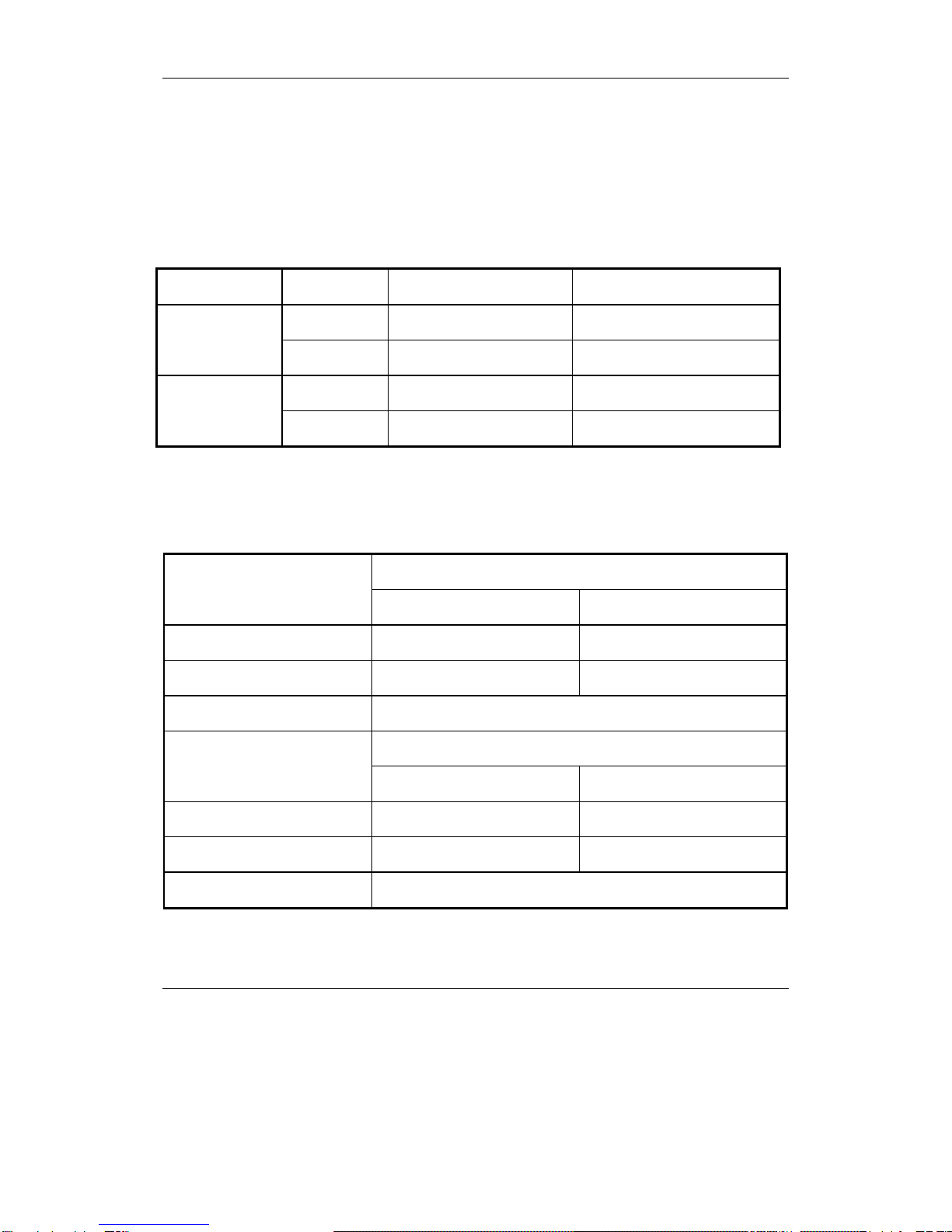
3.1.1 Signal input
Temperature sensor signal (indoor temperature, indoor coiled temperature, outdoor coiled
temperature); remote control signal; emergency switch input; auto diagnosis/ time-shortening input; fan
speed (high/medium/low/breeze) input; (capacity, heating or cooling) input;AC zero passage;PG feedback.
3.1.2 Signal output
Display signals (SI, SCK, RCK); louver motor (1a, 1b, 1c, 1d); step motor(2a, 2b, 2c, 2d); anion/
Electronic dust collector; ultraviolet,Auxiliary electric heating; PG output; buzzer & buzzer power;
compressor; outdoor fan motor; 4-way reversing valve.
3.2 Control functions
3.2.1 Switches input:
Press on / off button when the air conditioner is in the off mode. The unit turns on and works at 24℃
in AUTO mode automatically. Press this button when the unit is running or in TEST RUN mode, air
conditioner is turned off.
Press the button for four seconds until the buzzer beeps twice. Air conditioner enters the TEST RUN
mode. During the period of test run, the air conditioner is controlled by remote controller. The air conditioner
will start the normal operation automatically if the test running time is for more than 15minutes. Air
conditioner will be stopped and exit the test running mode when users press on / off button which is on the
indoor unit or on the remote controller.
3.2.2 Timing on/off and program control
3.2.2.1 Turn on the air conditioner on timer
The air conditioner will start operation at the set time. “Timing on” function is only effective for one
time in 24 hours. If user turns on the air conditioner by pressing ON/OFF button on the remote controller
before the set time, then “Timing on” function will be cancelled. If user select “Timing on” when the air
conditioner is in on status, the unit will be turned off and it will be turned on at the set time. The original
display of “Timing on” is 12:00.
3.2.2.2 Turn off the air conditioner off timer
The air conditioner will exit running at the set time. “Timing off ” function is only effective for one time
in 24 hours. If user selects “Timing off” function when the air conditioner is in the off status, the unit will be
turned on and it will be turned off at the set time. If user turns off the air conditioner by hand before the set
time, then “Timing off” function will be cancelled. The original display of “Timing off” is 12:00.
3.2.2.3 Program control
The air conditioner will be turned on/off at the set time everyday. If user turns off the air conditioner
by hand before the set time, then “Timing off” function will be cancelled; but “Timing on” function is still
effective. If user turns on the air conditioner by hand before the set time, then “Timing on” function will be
cancelled; but “Timing off” function is still effective.