DENRYO PANcharge1k User manual
PANcharge1k
Battery Charger
User's Manual
Ver.1.00E

2
Table of Contents
1. Important Safety Instructions..........................3
1-1 General Safety Precautions.....................................................................3
1-2 Battery Precautions .................................................................................3
1-3 Electromagnetic Disturbance...................................................................4
2. Features ............................................................5
2-1 Mechanical Drawings...............................................................................5
2-2 Front Panel..............................................................................................5
2-3 Rear Panel...............................................................................................5
2-4. Specification ...........................................................................................6
3. Installation and Settings ..................................7
3-1. Installation location .................................................................................7
3-2. Battery Type............................................................................................7
3-3. Connection..............................................................................................8
3-4. Operation Setting....................................................................................9
4. Operation ........................................................10
4-1. Battery Charging Curve ........................................................................10
4-2. Operation and LED Indicators............................................................... 11
4-3. LED Indicator of Error...........................................................................12
4-4. Protection..............................................................................................12
5. Troubleshooting..............................................13
©2010-2018 DENRYO CO., LTD. All Rights Reserved.

3
1. Important Safety Instructions
1-1 General Safety Precautions
WARNING
Read following safety instructions carefully before installation.
Save these instructions of PANcharge1k battery charger and batteries. This manual contains
important safety and operating instructions.
Operate PANcharge1k in a well-ventilated and dry area. Do not exposed to rain or snow.
To reduce a risk of fire, do not cover or obstruct the ventilation enclosure.
To avoid a risk of fire and electric shocks, do not operate charger with damaged or undersized
cords.
To avoid the risk of fire and electric shocks, do not disassemble charger.
Note: Warranty not valid once PANcharge1k is disassembled.
To reduce the risk of electric shock, follow the steps below before wiring, maintenance and
cleaning.
Turn AC power switch off.
Remove AC power cord from the charger.
First remove the black charging clip from the battery then the red one.
By covering charging clips to avoid short circuit of charging terminal while turning switch ON.
Ground the earth cord with the power cord to reduce the risk of electric shock, to protect from
external radio interference and not to radiate harmful emissions. The earth cord is connecting
with the charger’s chassis.
To avoid the risk of electric shock and fire, adjust the AC power switch in the rear of the charger
to the same voltage as the input one. Plug the proper power cord to the plug-in. NEVER input
230Vac with the 115Vac setting. It may lead to a fire, electric shock, or charger damage.
NOTE
Once PANcharge1k is opened or modified, DENRYO CO., LTD. has the right
not to provide warranty service.
1-2 Battery Precautions
Read the instructions of battery carefully before operating.
Place battery in a well-ventilated and dry area. Do not exposed to rain or snow.
NEVER smoke or allow a spark or flame in vicinity of battery.
Be extra cautious to reduce risk of dropping metal tool onto battery. Remove personal metal
items such as rings, necklaces, and watches when working with battery.
The battery may make corrosive gas during charging. Keep ventilation well.
Protect eyes and clothes when you work close to battery. Do not get too close to the battery with
your eyes.
When moving the battery, removing wiring from the earth terminal at first. Make sure all the
optional accessories have been turned OFF to reduce the possibility of sparking.

4
1-3 Electromagnetic Disturbance
This charger is designed under the consideration of electromagnetic interference radiation and
immunity. However, installing without following this manual may cause the Interfere with radio
communication. Operation of this equipment in a residential area is likely to cause harmful interference.
When the interference happens because of the ON/OFF of the charger, follow one of the steps below
to solve the problem.
Reset the direction of receiver antenna or adjust the mounting location.
Set the charger apart farther from the receiver.
Do not connect the receiver and charger into in the same wall sockets.
5
2. Features
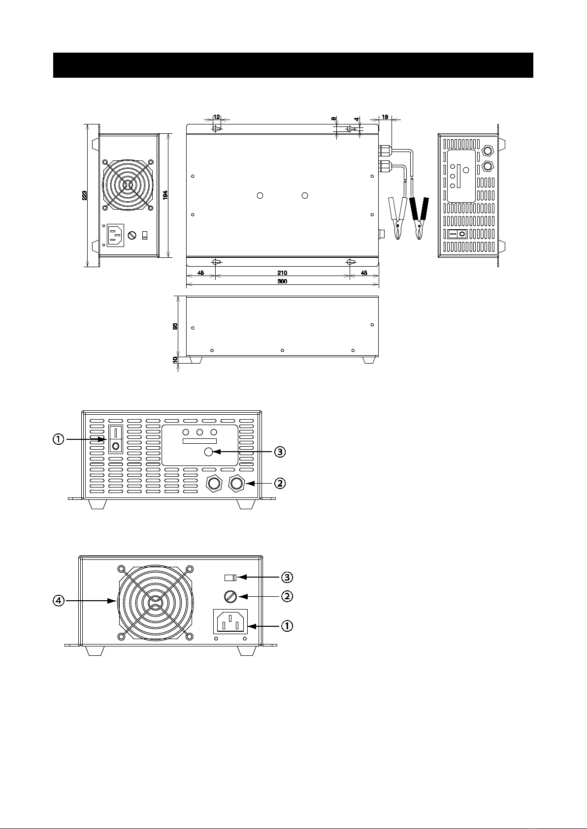
2-1 Mechanical Drawings
[mm]
2-2 Front Panel
①Power switch
“ I ” : ON ; “ O ” : OFF
②DC Output
“ + ” : Red ; “ - ” : Black
③Charging voltage select button
12V, 24V, 36V & 48V selectable
2-3 Rear Panel
①AC inlet
Only use cord attached for AC input 100-
120Vac. For AC input 200-240Vac,
prepare a cable applies to 200-240Vac.
②AC fuse holder
20A/250Vac, φ6.35mm, length 31.75mm
fuse built-in.
NOTE: Please replace the fuse with the same specification if replacement is required.
③AC Input voltage switch
AC 115/230Vac adjustable
Set “115” for input 115Vac; set “230” for input 230Vac.
NOTE: Set the switch with voltage as same as the AC input. DO NOT input 200Vac under the setting
of 115.

6
④Cooling fan
Fan works when charger temperature rises; fan stops when charger temperature drops.
Fan working depends on the different stages of rising temperature.
WARNING
PANcharge1k cools down by ventilation flows through the internal and
extracted by fan. Always locate charger in a well-
ventilation location to
make sure it keeps cooling down. If charger temperature is too high that
makes the protection function work; charger may stop working.
2-4. Specification
Model PANcharge1k
Input voltage 115/ 230Vac
Input voltage range 90~120Vac/ 180~240Vac
Input frequency 50/ 60Hz
No-load current Less than 0.1A
Max Efficiency (Full-load) 80% (Average)
Full-load Current Less than 20A (Average)
Battery voltage 12V 24V 36V 48V
Charging voltage range 8V~14.8V 16V~29.6V 30V~42V 40V~60V
Charging voltage 14.5V 29V 43.5V 58V
Float voltage 13.8V 27.6V 41.4V 55.2V
Max. charging current 30A 30A 25A 15A
Absorption min. current 2.25A 2.25A 2.25A 2.25A
Battery type Lead-acid battery
Normal temperature 25℃
Operating temperature 0~40℃
Storage temperature -20~60℃
Case temperature Less than 70℃
Humidity 5~95% RH (Non-condensing)
AC input code 3P-2P Power code with earth wire, 2,600mm
DC output code Red (+)/ Black (-) with clips, 1,080mm
Dimensions 300x223x95.3mm (Without foots and handle)
Weight 3.8kg
7
3. Installation and Settings
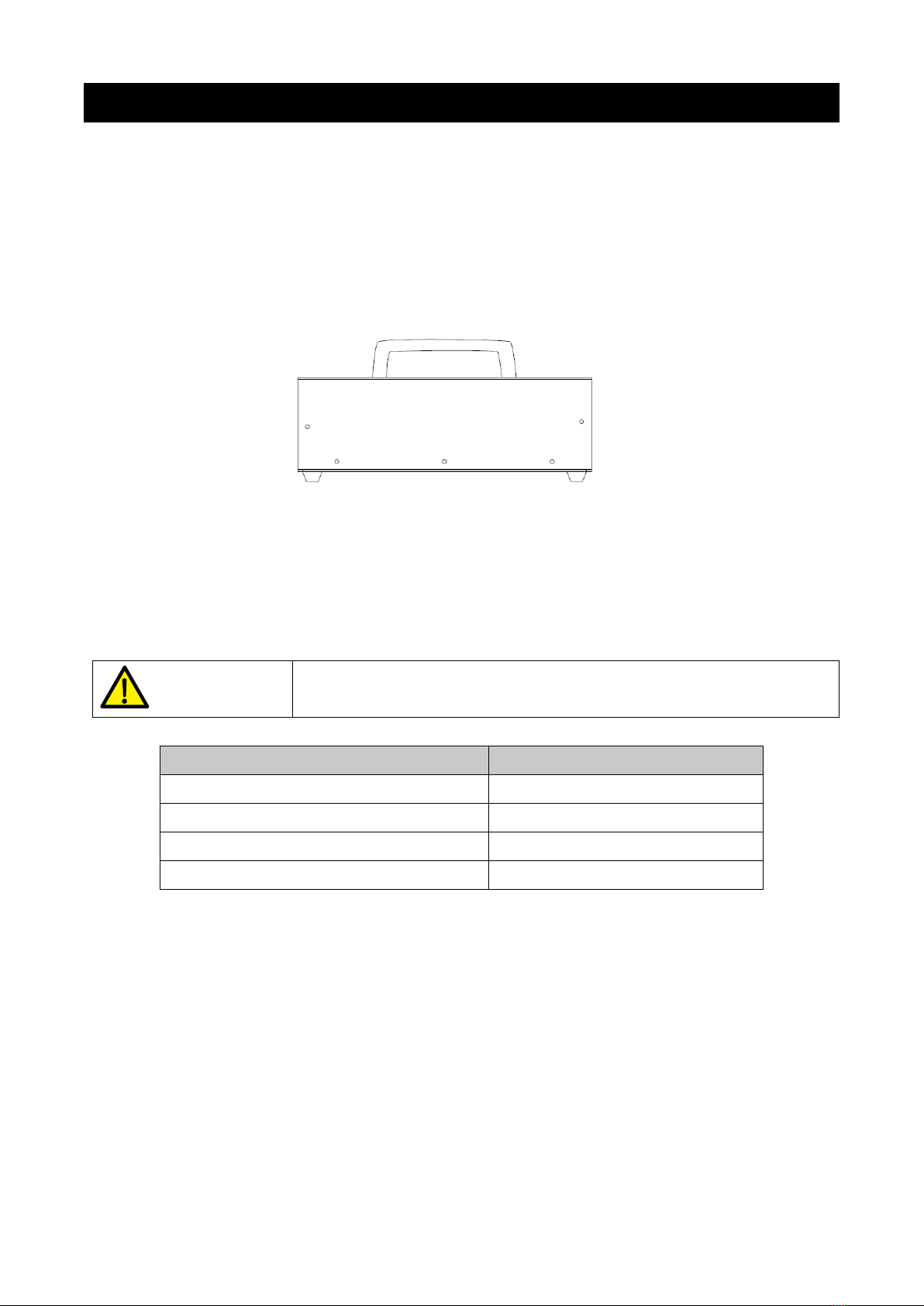
3-1. Installation location
Place PANcharge1k in a dry and clean area with well ventilation. Save at least 10 cm distance
from the charger.
Place in an area with ambient temperature 0℃~40℃.
Locate charger as far away from battery as the DC cables permit. Set charger in a safe location
far away from the risk of firing and gasoline.
Set PANcharge1k in a horizontal position as far as possible.
Picture 3-1 Mounting drawing.
3-2. Battery Type
PANcharge1k can charge lead acid batteries includes sealed lead acid battery and non-sealed lead
acid battery. Charging non lead acid batteries or lead acid batteries with higher capacity than the list
below may cause charger broken. In this case, the warranty is not applied.
WARNING
Only charge batteries within the capacity list below.
Charge voltage/ Max charge current Capacity of battery (Min.~ Max.)
12V / 30A 60 ~ 300Ah
24V / 30A 60 ~ 300Ah
36V / 25A 50 ~ 250Ah
48V / 15A 30 ~ 150Ah
8
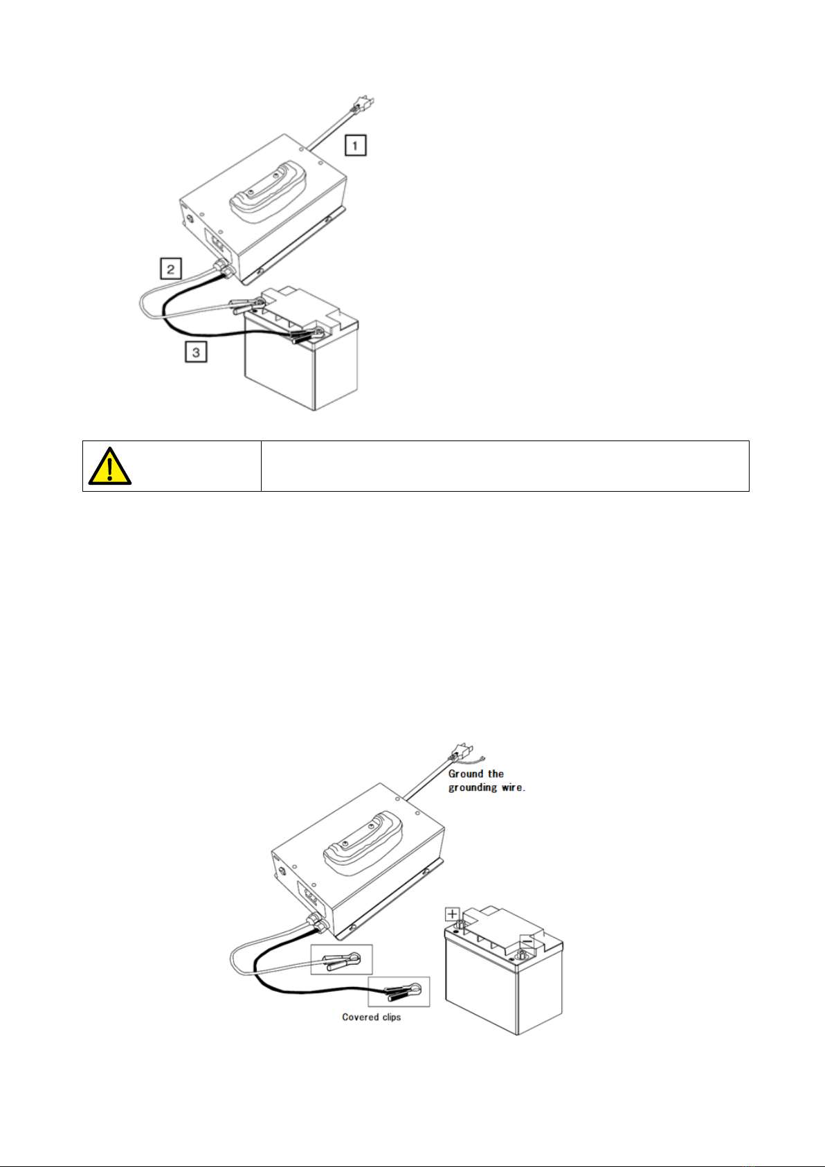
3-3. Connection
Picture 3-2 Wiring diagram
①AC power cord
②Battery(positive)*
③Battery(negative)*
*Connect battery after setting charging voltage.
Make sure AC power cable is plugging into connector (3P) firmly.
WARNING
Risk of electric shock.
Ground grounding wire on the plug of AC power cable properly. Improper connection may cause risk
of electric shock.
Battery charging cord
Do not connect battery and charging cord before setting charging voltage and charge begins.
Moreover, to prevent short circuit of charging clips, cover the clips when it is disconnected anything.
AC power cord
Make sure AC power switch is off.
Make sure grounding wire on the plug of AC power cable grounds properly.
Plug AC power cord into connector in the rear of charger.
Connect plug of AC power cord to power outlet.
Picture 3-3 Confirm the connection before charging begins.
9
3-4. Operation Setting
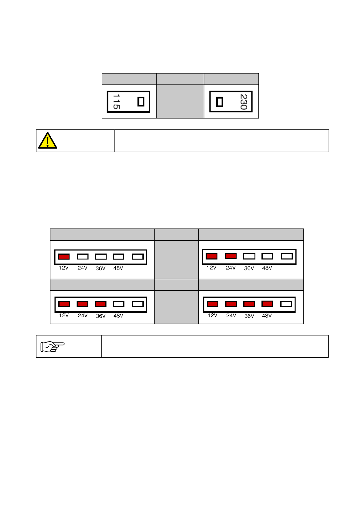
Step 1. Make sure the AC power voltage switch is setting correctly.
Step 2. Make sure nothing is connecting to charging clips.
Step 3. Set 115 when input 90-120Vac; set 230 when input 180-240Vac.
115Vac Input voltage 230Vac
Setting
WARNING
The AC power voltage setting must to be set as same as the input voltage.
Never input 230Vac under the setting of 115Vac.
Step 4. Press I on the AC power switch to turn charger on.
Step 5. All LED indicators light for 2 seconds. Afterward, red LED flashes indicate the charging clips
is disconnecting to battery. The rectangle LED indicates the set charging voltage.
Step 6. Set charging voltage by pressing the switch key around 0.5 seconds. The setting order is
12V →24V →36V →48V →12V…. The number of rectangle LED lights reflects to the
charging voltage user chose.
12V Setting 24V
LED status
36V Setting 48V
LED status
NOTE
The charging voltage must to be set as same as the battery voltage.
Step 6. Press O on the AC power switch to turn charge off. The setting is done.
10
4. Operation
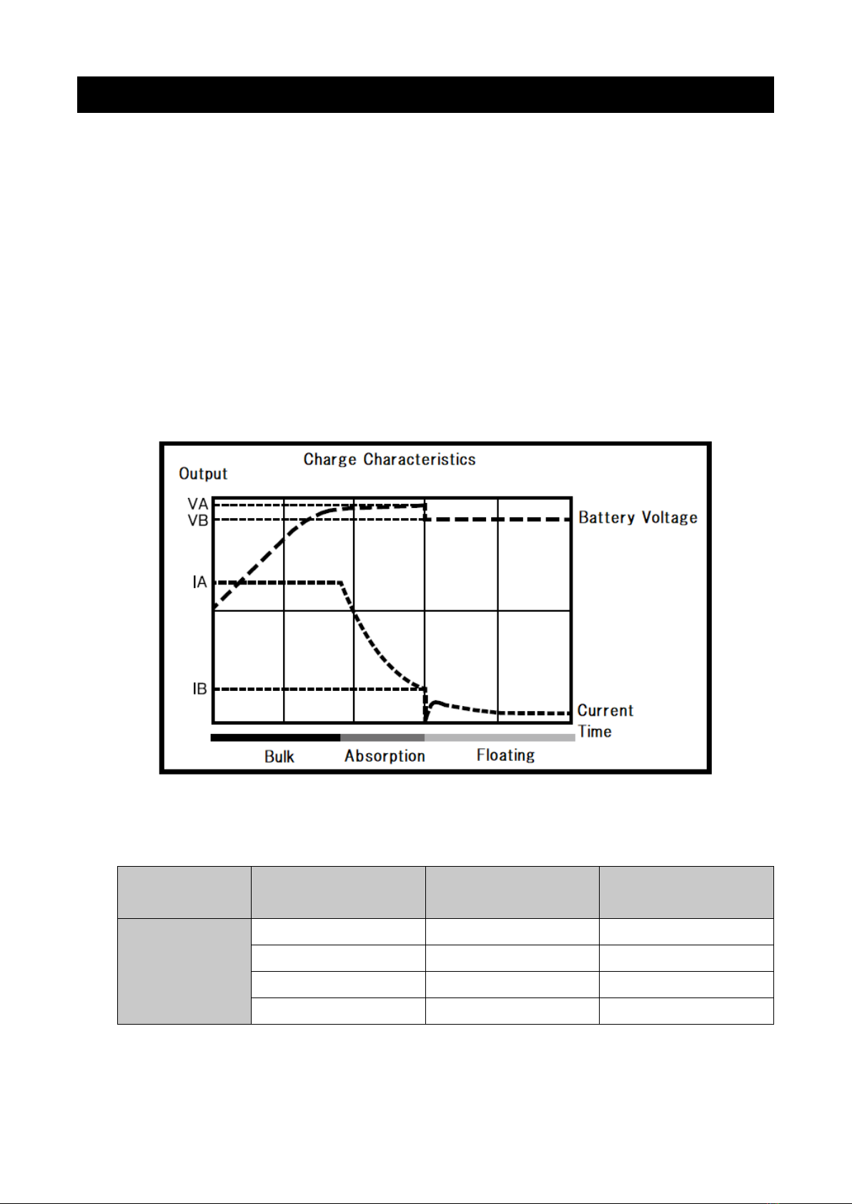
4-1. Battery Charging Curve
PANcharge1k is a charging voltage adjustable battery charger. The charging voltage is able to be
switched in accordance with the battery voltage of 12V, 24V, 36V or 48V by the battery voltage
setting switch on the charger.
3 Stage Charging
PANcharge1k charges by the 3 stage charging: bulk, absorption charging and floating charging. In
bulk charging stage, PANcharge1k outputs and charges by a constant current. In absorption
charging stage, battery voltage is constant but the current is decreasing, and battery generates
gas.
In the last stage of floating charging, charger charges with constant low voltage, maintains the
battery at 100% state of charge. If the battery does not connect to any load, it is normally charged
with a very low current.
Picture 4-1 Charge Characteristics
Table 4-1 Charging Status LED Indicator
3 stage
charging Bulk Absorption Floating
Round LED
indicator
Yellow Yellow Green
Light up Flash fast Flash slowly
↓↓↓
Flash slowly Flash very fast Flash fast

11
Table 4-2 3 Stage Charging Voltage & Current
Charging voltage & current Battery voltage
12V 24V 36V 48V
VA Charging voltage 14.5V 29V 43.5V 58V
VB Floating voltage 13.8V 27.6V 41.4V 55.2V
IA Max charging current 30A 30A 25A 15A
IB Ending current of absorption 2.25A 2.25A 2.25A 2.25A
4-2. Operation and LED Indicators
Step 1. Make sure the AC power voltage switch is correct set.
Step 2. Make sure the AC power switch is OFF and check the charging voltage setting is correct.
(Refer to P.9)
Step 3. Connect positive charging clip (red) to positive terminal of battery.
Step 4. Connect negative charging clip (black) to negative terminal of battery.
Step 5. Press I on the AC power switch to turn charger ON.
Step 6. All the LED light up for 2 seconds. Afterward, red LED lights up for 5 seconds. The
rectangle LED indicates the set charging voltage.
Step 7. Charging begins. The relay in the charger turns ON. A clink sound is normal.
Step 8. Yellow round LED: light up constantly
The LED lights yellow for 25 seconds means charging just begins and is charging slowly. At the
time, rectangle LED all light up initially, and turn to display the percentage of battery capacity
charged by the amount it lights.
Step 9. Yellow round LED: flash slowly
The LED turns to flash yellow slowly means it is charging in a constant current, the bulk charging
stage. At the time, the numbers rectangle LED light up increases with the capacity has been
charged.
Step 10. Yellow round LED: flash quickly
The LED turns to flash yellow quickly means it is charging in a constant voltage, the absorption
charging stage. At the time, the numbers rectangle LED light up increases with the capacity has
been charged.
Step 11. Yellow round LED: flash very quickly
The LED turns to flash yellow more quickly means it is about to turn to floating charging stage
soon.
Step 12. Green round LED: flash slowly
The LED turn to green means it has turned to the floating charging stage. Battery is full charged.
Step 13. Green round LED: flash quickly
The LED turn to flash green quickly means it is in the floating charging stage and charging
current is beyond 0.5A.
Step 14. Battery charging is finished. Follow steps below to remove the battery.
Turn charger OFF. The relay in the charger turns OFF. A clink sound is normal.
Remove the black charging clip from battery, then remove the red one.

12
4-3. LED Indicator of Error
Times
flashed
(times)
Possible cause Solution
2
Charging clips are not connecting to
the battery.
Fuse of output terminal is broken.
Connect charging clips to the battery.
Contact us or the distributor if
charging clips connected and charger
still errors.
3
The voltage of the Battery connected is
too high or too low that exceeding the
range of charging voltage.
Check if the battery voltage is available for
the charger. (Refer to P.6)
4 The temperature sensor in the charger
is short-circuited or opened.
The temperature sensor is error. Contact
us or the distributor.
5
The internal temperature is too high that
the over temperature protection is
working.
Wait for the charger to cool down. It
restarts automatically after temperature
down.
6 Other problem is happened. Contact us or the distributor.
4-4. Protection
Short-circuit protection: It will not be damaged even the output terminal is short-circuited.
Reverse connection protection: It will not be damaged even battery is reversely
connected.
Over temperature protection: Fan spins when charger internal temperature rises above a
certain level, and switches to strong or weak automatically depending on the temperature. Fan
stops when the temperature drops beyond a certain level. However, once the temperature rises
higher than the general level, LED turns to error display. Leave it for a while and wait for the
temperature drops to the normal level; charger recovers and charging restarts.
Input protection: An abnormal current flow in internal charger because of the charge itself or
other external factors, the protection works by melting the fuse of the input power.
Output protection: Due to the trouble of charger itself or other external factors, abnormal
current flows between the charger and battery. The fuse gets melt to protect the charger and
safety.

13
5. Troubleshooting
Refer to the table below to solve the certain problems.
Problem Possible cause Solution
LED does not work even the AC
power switch turns on.
AC power is not inputting. Check if the AC power cord is
connecting correctly.
Fuse of AC power is
broken
Check if fuse in the fuse holder in the
rear of the panel is broken. If this
problem still could not be fixed even
the fuse is exchanged, contact us or
the distributor.
Charger defect Contact us or the distributor.
Battery disconnected error even
the charging clips are
connecting to the battery.
(Round LED flashes red for two
times)
Bad connection between
charging clips and battery
terminals
Check if charging clips are connecting
firmly
Charger defect Contact us or the distributor.
Temperature protection error
displays and charging stops.
(Round LED flashes red for five
times)
Internal temperature is
too high that the over
temperature protection
works
Locate the charger in a ventilation-well
location and cool it down.
Battery could not be full charged
even it has been charged over
24 hours.
(Round LED flashes green)
Capacity of battery is too
large for the charger
Change to a higher output charger.
Current from battery is
flowing to the load
connected and the
battery cannot be
charged
Remove the load or turn the load off.
The cell of battery is
damaged
Change the battery.

14
DM-5103
DENRYO CO., LTD.
28-5, Nishinippori 2Chome, Arakawa-ku,
Tokyo 116-0013, Japan
Phone: +81-3-3802-3671
Fax: +81-3-3802-2974
Email: info-[email protected]
www.denryo.com/en
Table of contents


