DentalEZ Core User manual

CORETM Chair
User Manual

i
www.DentalEZ.com 866-DTE-INFO
i
DentalEZ®Equipment
PN: 2717-268B
Table of Contents
Section I Introduction
Product Overview ............................................... 1
Chair Features ....................................................2
Dimensions ........................................................ 3
Range of Motion ................................................ 4
Specications .................................................... 5
Classications ................................................... 6
Explanation of Symbols & Signs ...................... 6
Safety Precautions.............................................7
Section II Preinstallation
Packaging .......................................................... 9
Chair Placement ................................................ 11
Section III Installation
Chair Back ......................................................... 13
Delivery Units.................................................... 13
Seat Frame........................................................ 14
Foot Control ...................................................... 14
Touchpad Control............................................. 15
Upholstery......................................................... 16
Installation/Operation Checklist ..................... 18
Section IV Operation
Base Lowering Safety Switch.......................... 19
Chair Rotation................................................... 19
Armrests .......................................................... 20
Double Articulating Headrest......................... 20
Manual Chair Positioning ................................. 21
Automatic Chair Positioning........................... 22
Programming Chair Travel Limits .................. 23
Section V Care
Cleaning ............................................................27
Disinfecting...................................................... 29
Section VI User Service Information
Service Instruction ........................................... 31
Disposal of Equipment..................................... 31
Section VII Parts Lists/Diagrams
Hydraulic .......................................................... 33
Electrical .......................................................... 33
Controls............................................................ 33
Exterior Components...................................... 33
Upholstery........................................................ 33
EMC Information.............................................. 35
Limited Warranty............................................. 37

www.DentalEZ.com 866-DTE-INFO
ii
CORETM Chair
PN: 2717-268B
1
www.DentalEZ.com 866-DTE-INFO
1
DentalEZ®Equipment
PN: 2717-268B
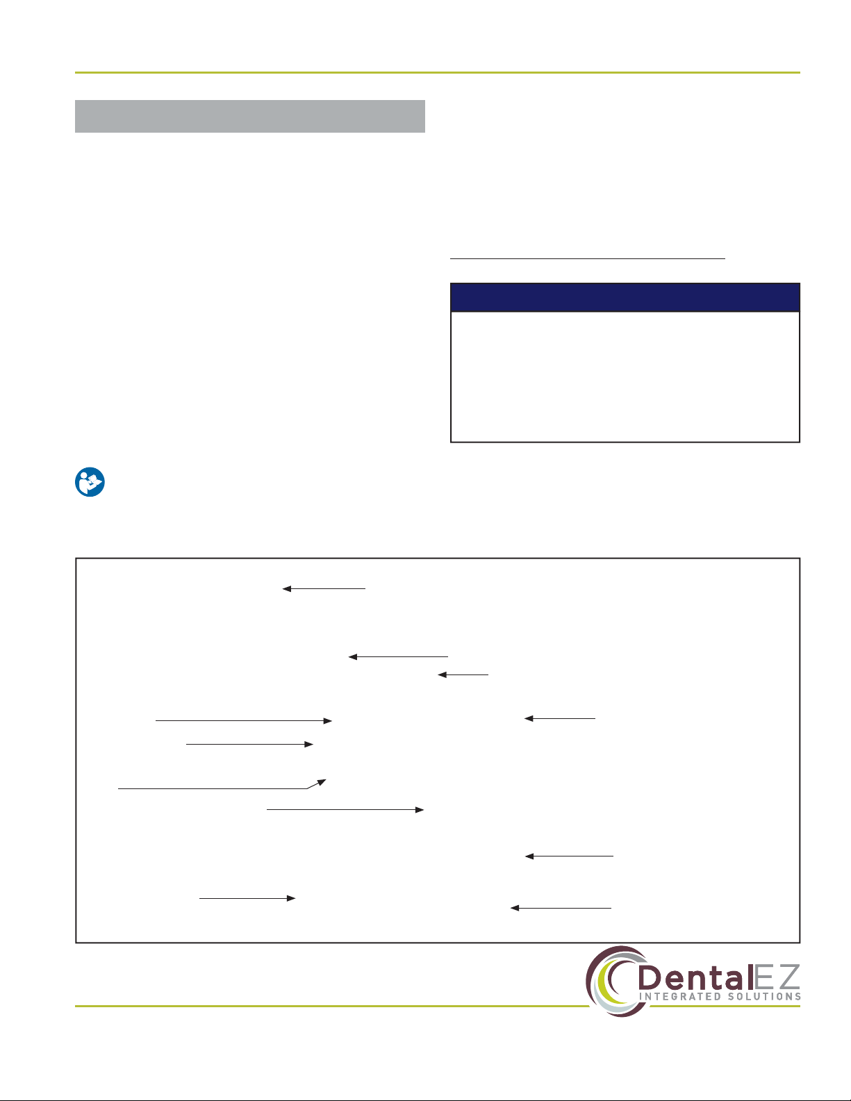
Section I Introduction
Before starting installation procedures, review
the illustration to become familiar with the
components of the CORE Chair (Figure 1).
After the CORE Chair is installed, review the
features, operation procedures, and care
guidelines with the doctor’s sta.
Leave this manual in the doctor’s oice.
Product Overview
This manual contains the installation, operation
and care instructions and user service
information for the DentalEZ® CORE™ Chair.
The CORE Chair is intended to be used by trained
professional dental care personnel only. The
dental chair supports a patient in a reclined,
seated position. Operators will be positioned
around the patient’s head as required for
optimum access for the specic procedure being
performed.
The CORE Chair is designed to provide trouble-
free service when installed, operated and cared
for according to the procedures set forth in this
manual.
To ensure proper installation, carefully read
all the instructions contained in this manual,
paying close attention to all warnings,
cautions and notes.
• Installation by an authorized DentalEZ
dealer service technician is recommended.
• For any questions about an order, please
contact a DentalEZ Equipment customer
service representative at 866-DTE-INFO.
NOTICE
Foot Control
Touchpad
Armrest
Brake
Headrest
Base (Cantilever Section)
Back
Armrest
Seat
Base (Pump) Cover
Base Plate
Figure 1. Main components of the CORE dental chair

www.DentalEZ.com 866-DTE-INFO
2
CORETM Chair
PN: 2717-268B
Chair Features
The CORE Chair oers state-of-the-art design for optimum operatory
performance with complete work comfort and unrestricted patient access.
In order to achieve the most eicient use in the operatory and understand
what the CORE Chair oers, here is a compilation of some features and
benets.
Standard Features
• Upholstered back assembly.
• Ergonomically designed base plate provides the dental team with free movement from nine o’clock
to twelve o’clock positions.
• Thin tapered back for better access to the oral cavity.
• Quiet and smooth hydraulic system for superior stability and smooth, quiet operation.
• Four operator-programmable positions increase eiciency by reducing the time needed for chair
adjustment.
• Cast iron chair frame and aluminum casting chair back, armrest, headrest and base provide superior
durability.
• Flip-down armrests allow for easy patient entry and
exit, while also allowing the dentist to easily change
from left to right without the use of any tools.
• Chair brake at back provides easy adjustment.
• Durable Naugahyde® upholstery.
• Double articulating headrest.
• Base safety switch feature ensures nothing gets
caught underneath the base as it lowers.
Optional Features
• Wired foot control provides programmable preset
positioning.
• Touchpad control provides easy and rapid patient
positioning.
Section I Introduction

3
www.DentalEZ.com 866-DTE-INFO
3
DentalEZ®Equipment
PN: 2717-268B
Section I Introduction
Dimensions
Figure 2. Side upright, top view and side reclining dimensions for the CORE dental chair
57"
48¾"
29½"
17"
26⅜"
20⅜"
26⅜"
27⅞"
74"
20"
25⅝"
19¾"
9⅞"
18⅛"
17⅞"
11"39¾"
15"
16⅛"
19⅝"
8⅝"
www.DentalEZ.com 866-DTE-INFO
4
CORETM Chair
PN: 2717-268B
Section I Introduction
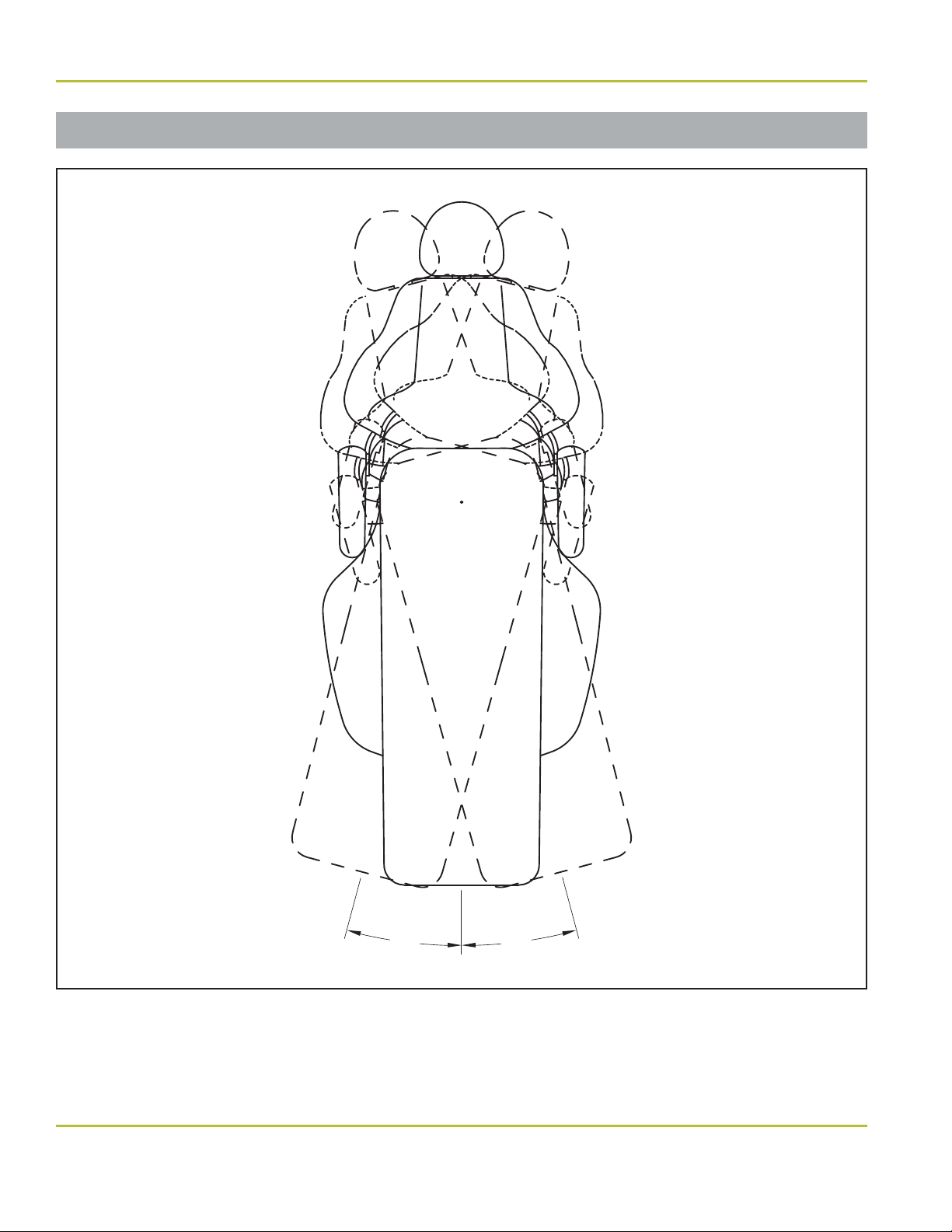
Range of Motion
Figure 3. Range of motion for the CORE dental chair
15
˚
15
˚
15° 15°

5
www.DentalEZ.com 866-DTE-INFO
5
DentalEZ®Equipment
PN: 2717-268B
Section I Introduction
Specications
Minimum Installation Space
• 10' ×10' (3 m ×3 m)
Base Plate Footprint
• 39¾" ×27⅞" (101 cm ×71 cm)
Recommended Environmental Conditions
Operation
• Temperature range: 41°F to 104°F (5°C to 40°C)
• Relative humidity range: 10% to 100%
• Atmospheric pressure range of 50 to 106 kPa
Power Supply
• 115V AC, 50/60 Hz, as applicable
• 230V AC, 50/60 Hz, as applicable
Fuse Type M
• F1/F2 - 10A, F3 - 100 mA
• F1/F2 - 6.3A, F3 - 63 mA
Control Voltage
• 5V DC
Shipping (Package) Weight
• Chair: 396.9 lb. (180 kg)
Empty Weight
• 300 lb. (136 kg)
Delivery System Capacity
• 125 lb. (56.6 kg)
Total Lift Capacity
• 450 lb. (204 kg)
Maximum Patient Weight
• Factory tested to lift a load of 300 lb. (136 kg)
Shipping (Package) Dimensions
• 57"L ×32"H ×34"W

www.DentalEZ.com 866-DTE-INFO
6
CORETM Chair
PN: 2717-268B
Explanation of Symbols & Signs
Classications
• Type of Protection Against Electric Shock:
Class 1 Equipment.
• Degree of Protection Against Electric Shock:
Type B Applied Parts. The upholstery is
considered an applied part.
• Flammable Gases: Equipment not suitable for
use in the presence of a ammable anesthetic
mixture with air, oxygen or nitrous oxide.
• Mode of Operation: Intermittent – 25 seconds
on, 300 seconds o.
Medical-General Medical Equipment
Certied as to electrical shock, re
and mechanical hazards only in
accordance with:
UL 60601-1
CAN/CSA C22.2 NO. 601.1
CAN/CSA C22.2 NO. 60601-1-08
ANSI/AAMI ES60601-1:2005
The authorized European representative is:
Dental Hygienics & Decontamination (DHD)
41 Blackwell Drive, Braintree Business Park
Braintree Essex, CM7 2PU, UK
Phone: +44 01787 877877 (ext. 200)
4010684
ETL CLASSIFIED
Section I Introduction
= Caution
= Warning
= Biohazard
= Warning - Dangerous Voltage
= General Mandatory Action
= Refer to Manual (Follow Instructions)
= Alternating Current
= Direct Current
= Protective Earth (Ground)
= Type B Applied Part
= European Certication
= Serial Number
= Manufacture Date
= Manufacturer
= Electromagnetic Radiation
= Do Not Trash
= Box Must Remain Upright
= Do Not Place Box on Unlevel Surface
= Do Not Stack Box
= Box Contents Safe Temperature Range
= Box Contents Safe Humidity Range

7
www.DentalEZ.com 866-DTE-INFO
7
DentalEZ®Equipment
PN: 2717-268B
Section I Introduction
Safety Precautions
• Before attempting to move the chair, it
must be lowered to its lowest position and
locked in place at zero degrees rotation. It
is strongly recommended that accessories,
such as lights and units, be removed before
moving.
• Rating of main circuit breakers should be
20 Amps maximum.
CAUTION
Isolating the unit from the supply mains is
accomplished by unplugging the unit from the
power receptacle.
NOTICE
Before proceeding with electrical
installation, all wiring must be in
accordance with NEC and local electrical
codes.
To avoid the risk of electrical shock, this
equipment must only be connected to a
supply mains with protective earth.
• Do not modify the CORE Chair without
permission from DentalEZ.
• The use of ACCESSORY equipment not
complying with the equivalent safety
requirements of this equipment may lead
to a reduced level of safety of the resulting
system. Consideration relating to the
choice shall include:
• Use of the accessory in the PATIENT
VICINITY
• Evidence that the safety certication
of the ACCESSORY has been
performed in accordance to the
appropriate IEC 60601-1 harmonized
standard.
• The plug cannot be located in a position
that requires tools to access.
• To prevent injury from falling or crush
hazards, patients should be seated upright
in the chair facing forward. Their head
should be on the headrest with their feet
at the toe of the chair. Their arms should
be on the armrests or folded across their
midsection.
• Headrest options that contain magnets can
interfere with the function of some medical
devices, including pacemakers.
WARNING

www.DentalEZ.com 866-DTE-INFO
8
CORETM Chair
PN: 2717-268B
9
www.DentalEZ.com 866-DTE-INFO
9
DentalEZ®Equipment
PN: 2717-268B
Section II Preinstallation
Packaging
• During transportation, the chair must be
at its lowest height and all attachments
must be secured in their lowest and
most central positions possible. Failure
to comply may result in injury and/or
damage to equipment.
• The chair is heavy and weighs approxi-
mately 300 lbs. Use assistance to remove
the chair from the pallet. Failure to do so,
may result in serious back injury.
• DO NOT CONNECT the chair POWER cord
until all shipping hardware is removed.
WARNING
• To avoid damage to the carton contents,
do not use a knife or sharp object to open
the packaging.
CAUTION
Tools Required
• Wire Cutters
• Adjustable Wrench
• 7/32" Hex Key
• Phillips-head Screwdriver
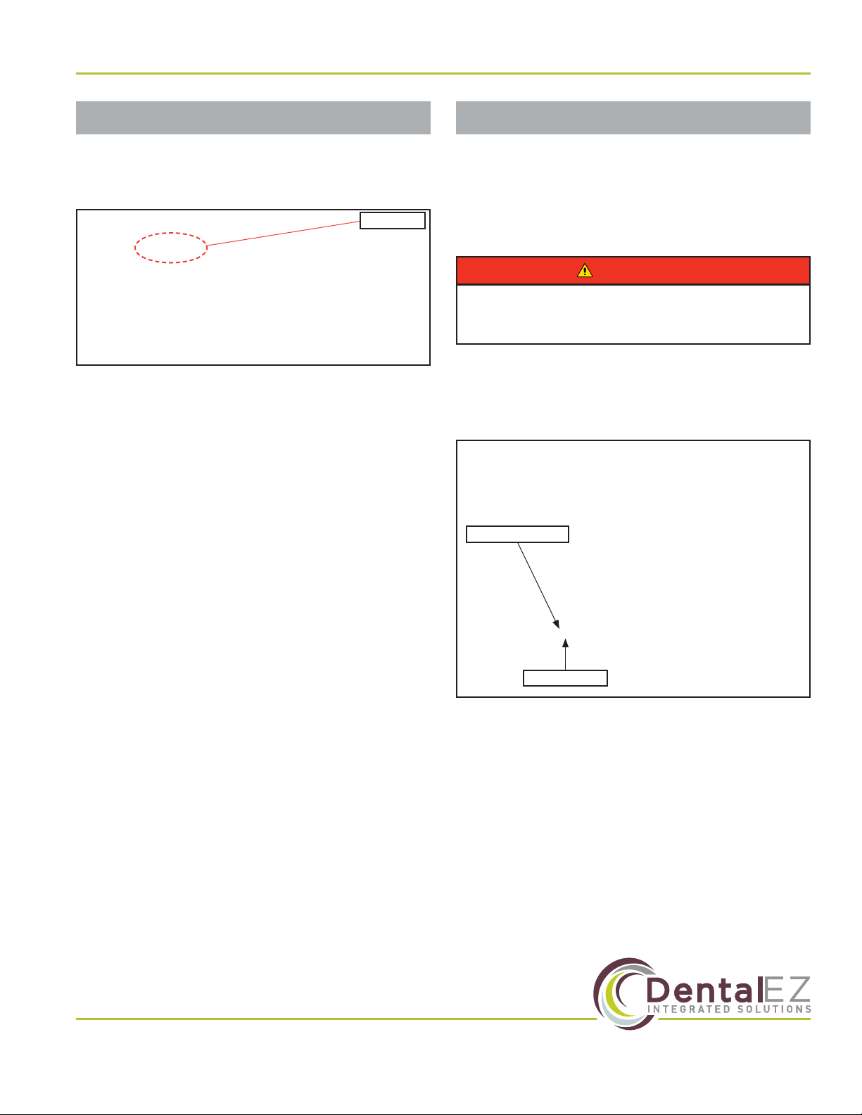
Unpacking Chair Carton
1. Use 7/32" hex key to remove the four bolts
holding the chair to the pallet. The bolts are
located on the underside of the pallet
(Figure 4).
2. Remove the outer strapping and plastic, then
remove the screws from the cardboard box,
one from each side and two from each end.
3. Remove the outer box top and set aside.
4. Remove the cardboard supports.
5. Remove all plastic wrapping and foam.
Figure 4. Bolts holding chair to wood pallet
Scan QR Code for Video Instructions:
CORE Chair - Unpacking and Setup
View Online Instructions

www.DentalEZ.com 866-DTE-INFO
10
CORETM Chair
PN: 2717-268B
6. Use wire cutters to cut the support straps/zip
ties located on both sides of the chair. Two ties
at either side secure the chair to the pallet. The
other ties secure the chair to itself (Figure 5).
7. To aid in pallet egress, remove the two corner
supports held in place by 10 screws (Figure 6).
8. Remove the chair from the pallet and place it
in the desired location before doing any other
installation.
9. Connect the chair power cord to a power outlet.
NOTE: The chair base will automatically lift to the
highest position.
Section II Preinstallation
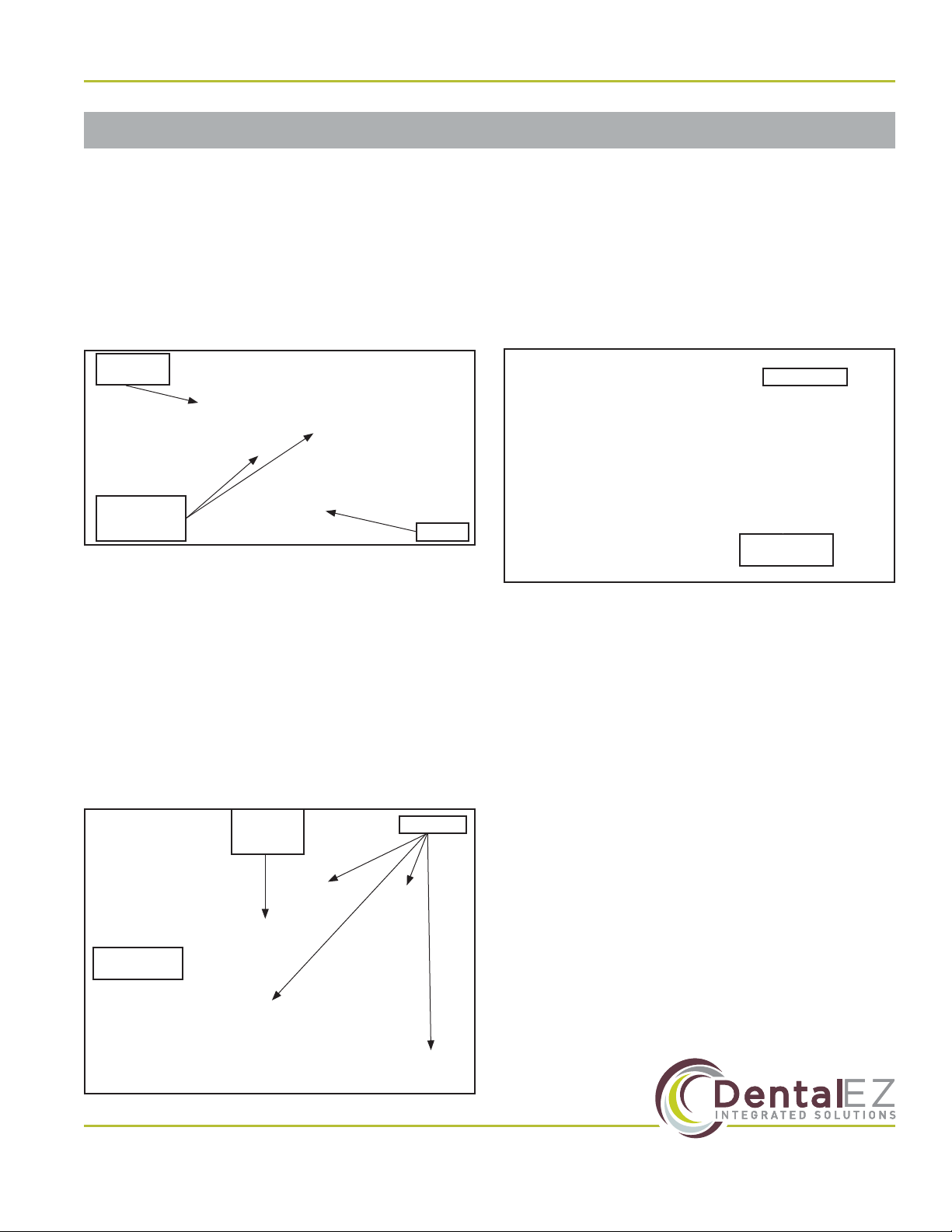
Upholstered
Back Assembly
Upholstered Seat
Upholstered
Armrests
Chair Controls
Headrest
Options
Hardware Package
Figure 7. CORE Chair packaging
Packaging (Continued)
Figure 6. Remove corner supports
Figure 5. Support straps/zip ties
Support Straps/ZipTies
Unpacking Upholstery Carton
Remove and set aside the following items from
the CORE Chair upholstery assembly packaging
(Figure 7):
• Upholstered Back Assembly
• Upholstered Seat
• Upholstered Armrests
• Headrest
• Hardware Package
• Any Additional Ordered Options
11
www.DentalEZ.com 866-DTE-INFO
11
DentalEZ®Equipment
PN: 2717-268B
Chair Placement
1. Taking into consideration the CORE Chair’s
dimensions, range of motion and specications
(see Section I Introduction), position the chair
in its permanent location on a smooth, hard
and level oor.
NOTE: Make sure the chair is placed where
nothing will interfere with its movement.
To prevent injury as a result of chair
tipping, chair must be placed on a smooth,
hard and level oor.
• DO NOT position the chair any place
where it would interfere with unplugging
the chair power cord.
WARNING
Section II Preinstallation

www.DentalEZ.com 866-DTE-INFO
12
CORETM Chair
PN: 2717-268B

13
www.DentalEZ.com 866-DTE-INFO
13
DentalEZ®Equipment
PN: 2717-268B
Chair Back
Tools Required
• 3/32" Hex Key
• Medium-strength Threadlocker
• Phillips-head Screwdriver
1. Loosen (but do not remove) the two set
screws with a 3/32" hex key and remove both
connector pins (Figure 8).
2. Lift the backrest to its upright position.
3. Line up the linkage holes and reinsert the
connector pins (Figure 9).
4. Apply medium-strength
threadlocker to the set
screw located on the end
of the backrest.
5. Using a 3/32" hex key,
tighten the set screw against the at surface of
the pin to hold the internal arm.
Figure 8. Bracket holes with inserted connector pins
Section III Installation
Delivery Units
Installation of the console mounted delivery
unit or the Magellan style delivery unit is
recommended before upholstery installation.
Follow the manufacturer’s instructions
supplied with the delivery unit.
Figure 9. Linkage holes

www.DentalEZ.com 866-DTE-INFO
14
CORETM Chair
PN: 2717-268B
Section III Installation
1. Remove cotter and clevis pins. Retain pins for
installation (Figure 10).
2. Remove the ve Phillips-head screws that hold
the seat upholstery to the seat frame. Retain
screws for installation.
3. Place a nylon washer onto each clevis pin and
slide into seat frame hole. Place the second
nylon washer onto the clevis pins and slide
into chair base hole. Replace cotter pin to hold
frame in place (Figure 11).
Seat Frame
Figure 10. Clevis pins with inserted cotter pins
Clevis Pins with Inserted Cotter Pins Seat Frame
Figure 11. Seat frame
Cotter Pin
Clevis Pin
Nylon
Washers
Seat Frame Chair Base
Foot Control
Tools Required
• 1/8" Hex Key
1. Disconnect the chair power.
2. Use a 1/8" hex key to remove the screws (2) on
the sides of the pump cover, then take the cover
oand set it aside (Figure 12).
3. On the control board, remove and discard
jumper (Figure 13).
To prevent any chance of electrical shock,
always disconnect power when indicated.
WARNING
Figure 12. Remove pump cover
Pump Cover
Screws
Figure 13. Remove and discard jumper on control board
15
www.DentalEZ.com 866-DTE-INFO
15
DentalEZ®Equipment
PN: 2717-268B
4. Connect the wire plug of the foot control into the
control board (Figure 14).
5. Reconnect the chair power and test the foot
control for proper function.
6. Reinstall the chair pump cover.
Touchpad Control
Tools Required
• 13 mm Wrench
• 1/8" Hex Key
1. Disconnect the chair power.
2. Locate bracket holes on the underside of the
armrest support (Figure 15).
3. Using a 13 mm wrench and the supplied
M8 × 1.25 × 30 mm hex head bolts (2), attach
the touchpad bracket to the existing bolt holes
located on the underside of the armrest support
(Figure 16).
To prevent any chance of electrical shock,
always disconnect power when indicated.
WARNING
Bracket Holes
Armrest Support
Figure 15. Locate bracket holes under armrest support
Figure 14. Connect wire plug of foot control
Wire Plug
Foot Control (Continued)
Section III Installation

www.DentalEZ.com 866-DTE-INFO
16
CORETM Chair
PN: 2717-268B
4. Using a 1/8" hex key, remove the screws (2) on
the sides of the pump cover, then take the cover
oand set it aside (Figure 17).
5. Connect the wire plug of the touchpad into the
supplied extension, then plug the extension into
the control board (Figure 18).
6. Reconnect the chair power and test the
touchpad for proper function.
7. Reinstall the chair pump cover.
Upholstery
• If the chair is part of an operatory, wait
until entire installation is complete before
installing upholstery. Failure to do so may
result in damaging the upholstery.
CAUTION
Tools Required
• Phillips-head Screwdriver
• 5/32" Hex Key
Seat
1. Align the studs located on the underside of
the upholstered seat with the holes in the seat
frame.
2. Use a Phillips-head screwdriver to replace the
ve previously removed screws. Attach the
upholstered seat to the seat frame (Figure 19).
Figure 16. Attach touchpad bracket to bolt holes
Bolt Holes for
Touchpad Bracket
Figure 17. Remove pump cover
Pump Cover
Screws
Touchpad Control (Continued)
Wire Plug
Figure 18. Connect wire plug of touchpad
Phillips-head
Screws (5)
Figure 19. Reattach upholstered seat to frame
Section III Installation
17
www.DentalEZ.com 866-DTE-INFO
17
DentalEZ®Equipment
PN: 2717-268B
Section III Installation
Upholstery (Continued)
Headrest
1. Slide the blade of the headrest into the
opening of the chair back casting.
2. Tighten the tension adjustment screws as
necessary until the desired slide tension is
reached (Figure 20).
Back
1. Align the two upper and two lower studs on
the chair back casting with the slide holes on
the back of the upholstered chair back.
2. Firmly press the upholstered chair back over
the studs and slide the upholstered chair back
down until all four (4) studs are locked into
place (Figure 21).
Armrests
1. Place each upholstered armrest onto the
chrome-plated arm supports.
2. From the underside of each arm, using two
(2) 5/32" hex screws, attach each upholstered
arm to the arm supports (Figure 22).
Slide Chair
Back
Down
Studs (4)
Slide Holes
(4)
Figure 21. Attach upholstered chair back to casting
Figure 20. Tighten tension adjustment screws
Tension
Adjustment
Screws Blade
Chair Back
Casting
Hex Screws
(2)
Arm Support
Figure 22. Attach arm to arm support
Other manuals for Core
2
Table of contents
Other DentalEZ Indoor Furnishing manuals


Popular Indoor Furnishing manuals by other brands


Whittier Wood
Whittier Wood 5618RGB Assembly instructions

2K Furniture Designs
2K Furniture Designs D505-T Assembly instructions

Bartscher
Bartscher 601182 Original instructions for use

IKEA
IKEA Ransby Assembly instructions

Next
Next 290242 Assembly instructions

Signature Design by Ashley
Signature Design by Ashley 10028211 Assembly instructions