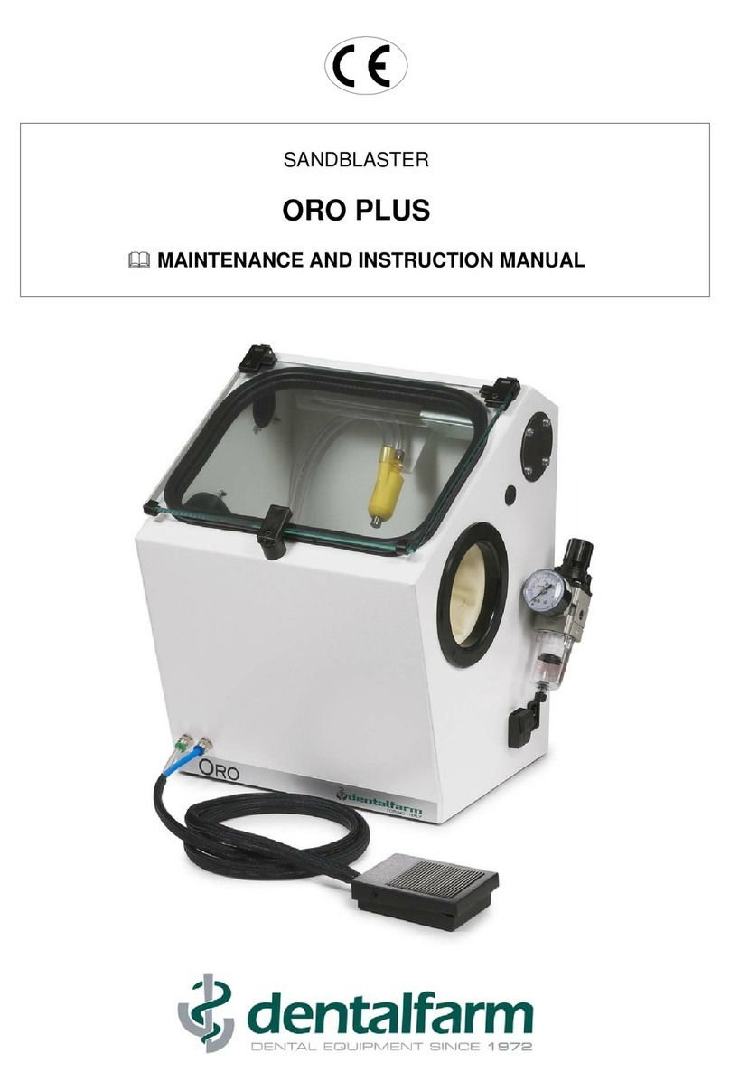
dentalfarm BASE Evo D.O.S. Operating instructions

SANDBLASTER
BASE Evo D.O.S.
USER AND MAINTENANCE MANUAL

1. TECHNICAL DETAILS
Height 445 mm
Width 415 mm
Depth 370 mm at base – 465 mm overall
Net and Gross weight 15,0 kg – 17,5 kg
Voltage 230 V - 50 Hz (different tensions available on demand)
Absorption 140 W - 3,0 A
Lighting Energy-saving 42 LED circuit
Dust filtering system Possibility to add-on the built-in WAFIS system or PRO-3;
compatible with traditional extractors
Devesting pressure min 2,5 BAR - max 6,0 BAR
Air consumption 100 l/min at 4 BAR
Blasting nozzle ∅3,0 mm tungsten carbide nozzles
Abrasive grainsize min - max mesh 80 (200µ) – mesh 36 (500µ)
Microblasting pressure min1,5 BAR – max 6,0 BAR
Air consumption (∅0,8mm) 15 l/min at 2 BAR
Air consumption (∅2,0mm) 120 l/min at 4 BAR
Standard nozzles 2 x ∅0,8 mm tungsten carbide nozzles
Abrasive grainsize min - max mesh 270 (50µ) – mesh 60 (250µ)

2. DESCRIPTION
BASE Evoluzione DOS is a sandblasting unit designed for devesting and finishing
operations in the Dental and Jewellery field.
The main features of the machine are: the ergonomic layout of the working chamber, the
safety of use, and the trouble-free structure of the mechanical installation. BASE
Evoluzione DOS is equipped with useful accessories and ensures a fast, practical and
accurate work. The unit consists of a devesting projector and of 2 DOS tanks, featuring a
pressure release system, very quick stop of the blasting jet and D.O.S. (Dry Oxyde
System): this system has been designed with the aim to dry up fine abrasives improving
their flowability.
The unit can operate with three different abrasive media. It is also possible to upgrade
the unit to 3 or 4 microblasting tanks, thus offering the possibility to work with 5
different abrasive media.
The sandblasting process originates toxic dust which must not be inhaled; for this reason,
it is absolutely forbidden to operate the machine if a proper suction system has not
been previously connected to the sandblaster.
DENTALFARM has developed the so-called W.A.FI.S. (WATER AIR FILTERING
SYSTEM), a patented solution which eliminates airborne dust thanks to the combined
action of water and air pressure, in compliance with hygiene and safety regulations. The
WAFIS system can be easily connected on the top left side of the machine and starts
automatically when the sandblaster is switched on.
DENTALFARM ranges also include PRO-3 and PRO-3 Shake suction units, which can be
easily connected to any sandblasting machine.
3. TECHNICAL REFERENCE REGULATIONS AND TEST PROCEDURES
The appliance is mass-manufactured by DENTALFARM in compliance with technical and
safety rules in force, as provided for by the Machinery Directive 2006/42 EEC.
Careful inspection and full routine testing is carried out singularly on each machine which
is furtherly processed by an automatic testing installation assuring compliance with the
fixed limits
According to International regulations, this unit has been classified as AEE
(electric and electronic device, whose correct operation depends on electric
currents and electromagnetic fields) and as a consequence, at the end of its
lifetime, it can not be treated as normal waste material but it must be
disposed separately, complying with Directive 2002/96/EEC.

4. INSTALLATION INSTRUCTIONS
/!\
ATTENTION
Installation of this machine is quite easy but must be carried out paying
utmost attention in order to avoid any mistake which may originate
problems, inconveniences and even damages during operation.
1. Place the machine on a proper workbench, which must be stable and strong enough to
stand the machine safely. Keep a sufficient distance (10/15 cm) on the right side of the
machine for the pipes and the feeding cables, as well as in order to have access to the
shutter and the filter. If a built-in WAFIS system is present, preferably choose a
workbench and a position (for instance on the bench edge) allowing the exhaust pipe to
fall perpendicularly into the collection tank.
2. Insert the quick clutch fitting on the male intake (A) located on the right side of the unit
and connect the pneumatic feeding pipe (polyethylene or rilsan, with diameter ∅8x6)
to the pipe-fitting. It is also possible to use a ∅12x6 elastic feeding pipe, by using the
fitting supplied with the unit.
3. Connect the electric feeding cable to the pre-fitted electric socket on the unit (B) and
plug into an approved 220v AC - 50Hz network socket with ground connection.
4. Install the preferred suction system; WAFIS, PRO-3 or any other.
The built-in WAFIS should be installed on the top left side of the
unit: unscrew the 4 screws fixing the black collection intake and
mount the WAFIS, unscrew the cap (C) and replace it by the pipe-
fitting delivered in the package, put together with the other portion
of pipe and plug the feeding cable into the electric socket (D).
PRO-3 suction units should be
connected by inserting the
collection pipe into the pre-fitted
intake.
Any other suction system can
be connected to the black
collection intake by means of flexible piping; the
inside manifold fits a ∅30mm pipe, the outside
manifold fits a ∅40mm pipe.
5. Adjust the air flow to avoid the machine being under pressure. Slightly turn the mobile
section of the adjusting valve when the suction system is on and stop when you notice
that the gloves are still slightly inflated.
6. Lift the window and fill the hopper with the appropriate abrasive (observe the
indications below as for dimensions of nozzles and correct working pressure).

Name Code Description
CROMCOR AP-036
Brown corundum, grainsize 36 (500 µ) for chrome-cobalt
(may be used with nozzle ∅3,5 – white cap – upon request)
OROCOR AP-046
White corundum, grainsize 46 (350 µ) for non-precious alloys
(may be used with standard nozzle ∅3,0)
SUPERCOR AP-060
White corundum, grainsize 60 (250 µ) for precious alloys
(may be used with standard nozzle ∅3,0)
OROBLAST AP-300
Glassbeads, 200 µ– for satin-finishing of any metal
(may be used with standard nozzle ∅3,0)
7. Microblasting tanks (EASY tanks) are identical in layout, but can feature different
components (calibrated metering system) and external nozzles which vary
according to the abrasive mixture they can supply; it is therefore necessary to
observe the indications written on the identifying labels. Should you need to use an
abrasive compound of different grainsize (not listed below), it is possible to request the
assembly parts and to replace them.
The unit can thus operate with three different abrasive media. It is also possible to
upgrade the unit to 3 or 4 microblasting tanks, thus offering the possibility to work with
4 different abrasive media. To pour abrasive media into the tank, unscrew the tank cap
and fill in the tank till approximately 2/3 of its capacity (observe the maximum level
marked on the label); then close the tank.
Strictly observe the following parameters, based on the abrasive grainsize.
TREATMENT TANK
(meter system) RECOMMENDED
PRODUCT NOZZLE
DIAMETER PRESSURE
Surface roughness on
metals for composites A1072G
(coarse)
AP-060
Orange label
(AL2O3 60 - 250µ)
2,0 mm
(RMN046)
4 BAR
Surface roughness on
metals for composites A1072M
(medium)
AP-120
Pink label
(AL2O3120 - 105µ)
1,2 mm
(RMN043)
3/4 BAR
Surface roughness on
metals for ceramic or resin A1072M
(medium)
AP-150
Green label
(AL2O3150 - 95µ)
0,8 mm
(RMN044)
3/5 BAR
Surface roughness on
metals for ceramic A1072M
(medium)
AP-180
Red label
(AL2O3180 - 80µ)
0,8 mm
(RMN044)
3/5 BAR
Sculpture on ceramic A1072S
(fine)
AP-270
Yellow label
(AL2O3270 - 50µ)
0,5 mm
(RMN045)
3/5 BAR
Satin-finishing on any type
of metal A1072M
(medium)
AP-090
MICROBLAST
White label
Higher precision
0,8mm
Higher speed
1,2 mm
3/4 BAR
4/5 BAR
A longer nozzle with ∅0,8 mm size (RMN044L) is available on request to carry out
cleaning operations on ceramic prosthesis without metal support.

/!\
WARNING:
Very fine abrasives are highly sensitive to moisture and must be
stored in a dry place, after the can has been accurately sealed and
the dessiccant packet has been duly introduced into the can (if
needed, replace them periodically).
When filling the abrasive tanks, check the condition of the abrasive
product; if the moisture content is too high (bad flowability and
presence of clots), it is recommended to wait for about an hour
before use, so that the heating system can dry it up completely. It is
also of utmost importance to check the condition of the compressed
air which in no way must contain evidence of moisture or of any
polluting agents (oil, grease or rust).
5. INSTRUCTIONS FOR USE
• Press the switch to illuminate the working chamber and feed the operating controls.
/!\
ATTENTION:
May we remind that the sandblasting process will start only provided
the suction system is operating – as a consequence, the filtering
system MUST always be installed and OPERATED BEFORE you
start to work.
• Lift the window to introduce the pieces to be treated into the working chamber.
• Turn the selector switch knob to choose the type of blasting procedure you prefer –
references marked on the label are herewith specified.
POSITION OF THE
POINTER SELECTED FUNCTION
YELLOW DEVESTING OPERATIONS
GREEN MICROBLASTING FROM THE GREEN TANK
BLUE MICROBLASTING FROM THE BLUE TANK (if any)
RED MICROBLASTING FROM THE RED TANK (if any)
WHITE MICROBLASTING FROM THE WHITE TANK
• Press the foot control: when removing investment, air gets to the projector and is
mixed up with abrasive coming from the working chamber, thus delivering the air-
abrasive mixture necessary to carry out the treatment; in case of microblasting, air
enters the selected tank putting it under pressure, it gets mixed with abrasive
micrograins and will then be propelled through the spraying nozzle.
• Adjust the working pressure by means of the pressure adjusting device located next to
the pressure gauge: lift the knob and turn it rightwards (to increase) or leftwards (to
decrease). To lock the knob, push the knob back down.
NOTE
The abrasive used for finishing operations (tanks) cannot be re-utilized and will
fall inside the working chamber, thus mixing up with corundum. This
phenomenon will not affect your work (except if microbeads are being used),
but the abrasive shall be replaced more frequently.

The microprojectors are ideally positioned in the centre of the working chamber to facilitate
use with both hands. We recommend to put back them in place on their support at the end
of the work.
The window is made of anti-scratch polycarbonate material, resisting to the rebounding
abrasive grains. We recommend to use a soft cloth to clean it and to remove the dust from
inside and the use of ptotection screens (code 1000532).
6.MAINTENANCE
Many of the components of any sandblasting machine are subject to wear: this is
caused by the circulation of abrasive media; the instructions for a careful maintenance of
the machine as well as the operations to replace the damaged or worn out parts are
specified here below.
/!\
ATTENTION:
Before carrying out any maintenance operation inside the working
chamber or technical repair of the connections, remove the feeding
cable both from network socket and from the rear of the machine; in
such a way, both the electric and pneumatic installation of the unit will
be fully disconnected.
Should you have any doubts or difficulties, please contact our
Technical Service to avoid any risks or damages.
Cleaning of the 5my filter
A 5my filter, fitted on the right side of the sandblaster, prevents fine dust from damaging
internal components. Remove the inspection cap every 2-3 months and blow the filter with
compressed air to clean it from dust sediment.
Replacement of the polycarbonate window
Although the window is anti-scratch, it may be damaged by an extensive use (or a bad
maintenance). Replacement is very simple: locate the screws which fix the window to the
hinges and unscrew them.
Replacement of the plastic protection screens of the glass window: remove the fixing
clips, clean accurately the glass and place a new protection screen.
Replacement of gloves
The gloves are made of highly resistant rubber, but are subject to the natural ageing of
rubber and to the action of sweat (produced by hands). This cause them to dry up. To
replace them, unscrew the flange screws and fit a new pair of gloves into the proper seat.
Replacement of the devesting nozzle
The devesting nozzle, even if made of tungsten carbide, known as a very hard material,
will inevitably wear out, due to the continuous flow of abrasive and will therefore need to
be replaced periodically. Remove the nozzle cap and insert a new group, paying attention
to thoroughly fit it into the plastic body.
Replacement of nozzles
Nozzles of the microblasting tanks are also subject to wear and need to be replaced. To
do this, unscrew the ring nut and assemble the new nozzle.

Replacement of abrasive media
To replace used abrasive media, pull the machine forward, lift the internal filtering grid,
remove the cap from the bottom of the working chamber and let abrasive flow out,
collecting it into a proper container.
Replacement of parts subject to wear (pipe, pipe-fittings, microprojector body)
The polyurethan pipe, the connection fitting and the microprojector body where abrasive
flows will inevitably wear out and need to be replaced regularly. To replace the
microprojector body, follow the same instructions specified for the nozzle; to replace pipes
or pipe-fittings, capsize the unit and work under the container. It is also possible to
disconnect each tank for easier operation, simply unscrewing the nuts fixing it to the
housing.
Replacement of tank internal components
Should it be necessary to replace the tank internal components like joints, air injectors,
abrasive outlet pipe, please contact our Technical Service.
Removal of a microblasting tank for repair purposes
The new tank units have been studied to facilitate your task during installation and
removal.
1. Unscrew the feeding pipe ring nut and disconnect the pipe
2. Unscrew the plastic ring nut and remove the microprojector pipe
3. Unscrew the two nuts fixing the tank to the suport, and unclutch the tank.
Procedure for the installation of an additional Modulo tank
• Disconnect the feeding cable and the quick clutch pipe-fitting of the compressed air
• Remove the sheet steel closing the tank seat by making it rotate on itself
• Fix the tank in place by means of the two nuts (adjust it so as to have the blue plastic
pipe-fitting towards the centre of the machine)
• Remove the cap from a free pipe-fitting on the selector and introduce the air inlet pipe
• From inside the working chamber, loosen the screw fixing the microprojector support
lower part and rotate it in order to locate the set up holes
• Drill the membrane of the rubber joint and let the free end of the handpiece pipe pass
through
• Connect the handpiece pipe to the blue pipe-fitting under the tank
• Insert the heater plug into an electric socket.

7. TROUBLESHOOTING
Problem: THE MACHINE DOES NOT START
Possible cause Remedy
Lack of tension Check: - magnetothermic switch
- socket supply switch
- fuses of the feeding board
Lack of distribution in the machine Check: - socket connection
- network fuse
Should this malfunction repeat, contact our
TECHNICAL SERVICE.
Problem: NO LIGHTING
Possible cause Remedy
Bad electrical connection Check that the electrical plug is correctly plugged in.
Shutter is damaged Check connections and operation (some dust could
have oxidized contacts so that they seized up). Try to
blow with compressed air and replace if needed.
Problem: NO AIR IS COMING OUT
Possible cause Remedy
Bad pneumatic connection Check connection to the compressor.
Internal pipes are clogged
Check connections and condition of pipes up to their
end (nozzles).
Air filter is clogged
Check and disassemble, if needed, the moisture
collection glass and replace the internal filtering
element.
Problem: THE BLASTING FLOW IS IREGULAR (devesting)
Possible cause Remedy
Compressor is not efficient enough
Verify the features of the compressor, as this must
provide a minimum power of 150 l / min (to ensure
proper performance) and a 100 l tank (to ensure
capacity).
Working pressure is not suitable for
the metal to be treated. Observe the prescriptions contained in the detail table
of this manual.
Abrasive not suitable As above.
Abrasive is exhausted Replace with new abrasive.
Nozzle is not suitable or is worn
out. Observe the prescriptions contained in the detail table
of this manual. Replace if needed.
Problem: NO ABRASIVE IS DISPENSED, ONLY AIR COMES OUT (devesting).
Possible cause Remedy
Nozzle is worn out. The nozzle is ∅3,0 mm, in case of excessive wear
and alteration of the diameter, replace it.
Nozzle is not properly positioned,
so abrasive is not supplied. The nozzle must entirely come out of the nozzle cap.

Problem: NO AIR COMES OUT FROM THE PROJECTOR (devesting)
Possible cause Remedy
The internal projector nozzle is
clogged. Remove the cap and clean the injector.
Solenoid valve is clogged.
Close air inlet, remove the coil and the core and clean;
eventually get in touch with our Technical Service.
Problem: NOZZLE-HOLDER CAP COMES OUT DURING WORK (devesting)
Possible cause Remedy
Both piping and nozzle are clogged. Close up the end of the nozzle and press the foot-
control; the operating air flow will thus be inverted,
eliminating any obstruction from inside the pipes.
Should this irregularity repeat too often, remove
abrasive from the hopper and filter it.
Worn out and pulverised abrasive. Replace the abrasive, as this could be mixed with fine
particles or investment residuals which will never go
through the nozzle spraying hole..
Problem: INTERNAL AIR LEAKAGE
Possibile causa Azione correttiva
Condensate discharge on the filter.
The condensate discharge is carried out by the lifting
of a ball cock. A sufficient level of pressure must be
provided for the valve to close.
Internal pipes are disconnected
Check condition of the piping. Polyethylene pipes
might not be perfectly calibrated; try to cut out a small
portion from the end of the pipe and insert it into the
pipe-fitting; if needed, replace the pipe.
Problem: THE BLASTING JET IS UNSTEADY
Possible cause Remedy
Nozzle is clogged or worn out.
Unscrew nozzle fixing nut, clean both the hole and
microprojector components (especially the thread) -
re-assemble without forgetting the seal washer.
If necessary, replace the damaged parts.
Microprojector feeding pipe is worn
out, bent or clogged If the pipe is worn out or bent, replace it. If it is
clogged, disassemble the nozzle and let air come out.
The abrasive mixture is too rich in
aluminium oxide, i.e. loss of
sharpness
Abrasive container is overfilled, discharge it.
Pipe bending under the containers may collect
abrasive at the end of the work, when the valve
releases pressure; it is possible to limit this reaction
reducing this pipe bending at the minimum.
Damp aluminium oxide causing bad
flowing. Empty the tank, possibly disconnect it from the
machine and turn it upside down, blow with clean air
in order to dry up all the internal pipings, then heat
and dry up the abrasive product and fill in again.
Compressed air filled with
condensation or oily particles. Fine abrasive compounds are particularly sensitive to
moisture and, as mechanic pickling agents, they hold
the polluting agents. Therefore it is important to
protect the efficiency of the product by installing
adequate filtering and drying systems on the air
installation.

Problem: NO ABRASIVE COMING OUT, INTERNAL LEAKAGE.
Possible cause Remedy
Worn pipe-fittings or punched
microprojector pipe. The components of the circuit located after the tank –
where the abrasive flows - are subject to wear. It is
recommended to prevent any possible break by
replacing these components each 6-12 months,
according to the workload.
Problem: ABRASIVE TANK IS NOT UNDER PRESSURE
Possible cause Remedy
Joints are not perfectly airtight Check whether cap has been correctly tightened.
Disconnect the tank from the machine, disassemble
and clean it.

8. EXPLODED DRAWING AND SPARE PART LIST - BASE EVO DOS table 1
NO.
CODE
DESCRIPTION
1
1000534
COMPLETE LED LIGHTING SYSTEM
2
1072037
LIGHTING SYSTEM BASE
3
1072040
ELECTRONIC BALLAST
4
1072041
42 LED CIRCUIT
5
1072038
LIGHTING SYSTEM COVER
6
1069010
PVC WASHER FOR HINGE
7
105
4019A6
HINGE FIXED PART HOLE 6mm
8
RCB016A
HINGE MOVABLE PART
9
RMBL028
HINGE PIVOT
10
RWA007
SUCTION UNIT INLET
11
RWA006
JOINT FOR SUCTION INLET
12
1072029
POLYCARBONATE WINDOW
1000532
CONF. x 6 GLASS PROTECTION SCREEN
RCB042
PROTECTION SCREEN
FIXING CLIPS
13
1064015
WINDOW JOINT
14
1072021
WORKING CHAMBER FOR BASE SANDBLASTERS
15
1073011
SUPPORT FOR 4 MICROPROJECTORS
16
RS521
COMPLETE DEVESTING PROJECTOR
17
1072028
BASE PROJECTOR SUPPORT
18
1000605
COMPLETE MICROPROJECTOR (specify colour
and nozzle)
19
NPS001
RUBBER AIR BLOWER
20
NEA123
CLIP
21
NVT151
MALE KNOB M4x10
22
1072025
ABRASIVE GRID
23
NEA115
PLASTIC RING D. 14
24
NVP030
PLASTIC CAP D.
=
31
25
1072024
LOWER CLOSURE
26
NVG049
RUBBER FOOT H
=
19
27
NEC050
ELECTRIC FOOT CONTRO
L
28
RCB017
GLOVE FLANGE
29
RCS130
PAIR OF GLOVES
30
NEC018
PROTECTED BIPOLAR SWITCH
31
NEA046
PLUG AND FUSEHOLDER
32
NEA071
5x20 FUSE 6,3 A
33
NEV013
ELECTRIC CABLE 3x1 PLUG / SOCKET
34
NES030
3
-
WAY SOLENOID VALVE
-
220v
35
NVT141
GRADUATED KNOB
36
1072032E
BASE EVO SELECTOR SWITCH LABEL
38
1069003
SELECTOR SWITCH SUPPORT
39
1000510
-
6
6
-
WAY
-
SELECOTR SWITCH COMPLETE
40
NEA047
FEMALE SOCKET
41
NPS029
FILTER AND REDUCER 1/8
42
1072026
BASE/MICRA REDUCER AND PRESSURE GAUGE HOLDER
43
NPS040
PRESS
URE GAUGE 0
-
61/8
44
1072033
COVER ON SUCTION INLET


EXPLODED DRAWING AND SPARE PART LIST - BASE EVO DOS table 2
NO.
CODE
DESCRIPTION
45
100072DN
COMPLETE DOS TANK
46
1072008
FILTER CONTAINER
47
1072009
CAP WITH 5MY FILTER
48
1072034
KEY FOR 5MY FILTER
-
BASE/MICRA
49
NPR220
PIPE
-
FITTING 7 1/8
50
NPR119
STRAIGHT MALE PIPE
-
FITTING 8x6 1/8
51
NPR303
RAPID FEMALE CLUTCH 1/8
52
NPR304
MALE FEMALE CLUTCH 1/8
53
1072023
HOLDER FOR 4 TANKS, BASE SANDBLASTER
54
NVG048
RUBBER
FEET H
=
12
55
NEA048
TWO
-
POLE PLUG
56
NES037
TRANSFORMER 230V 24V
-
40W
57
NPR223
MALE PIPE
-
FITTING 1/8
58
NVT165
FEMALE CAP G1
59
1072003
COMPLETE ABRASIVE TANK
60
RBP019
CASE FOR HEATING RESISTANCE
61
RMN034
JOINT FOR TANK
62
1072001
BASE OF D.O.
S. TANK
63
NES012
HEATING RESISTANCE 24V
-
20W
64
NEV008
ELECTRICAL CABLE 2X0,75 WITH PLUG
65
NEC070
50 DEGREE THERMOSTAT
66
NPV020
SINTERED AIR INJECTOR
67
NPOR2043
OR JOINT 2043
68
NPR111
STRAIGHT MALE PIPE
-
FITTING 6x4 1/8
69
1072004
AIR BLOWER ASSE
MBLY PIPE
-
FITTING
70
NPR111P
STRAIGHT PLASTIC PIPE
-
FITTING M 6x4 1/8
71
1072005
ABRASIVE PIPE ASSEMBLY PIPE
-
FITTING
72
1072006
ABRASIVE OUTLET CAP
73
1072007
TERMINAL CAP ON ABRASIVE CAP
74
NPV042
SOFT POLYURETHAN PIPE 6x4
75
NEV030
SHEATH D.
=
6
76
1067005
ABRASIVE PIPE MOUNTING PIPE
-
FITTING
77
1067022
HANDLE WASHER (specify colour)
78
1067006
MICROPROJECTOR HANDLE
79
NPOR2012
OR JOINT 2012
80
RMN043
TUNGSTEN CARBIDE NOZZLE D.
=
1,2
-
RMN044
TUNGSTEN CARBIDE NOZZLE D.
=
0,8
-
RMN045
TUNGSTEN CARB
IDENOZZLED.
=
0,5
-
RMN046
TUNGSTEN CARBIDE NOZZLE D.
=
2,0
-
RMN047
TUNGSTEN CARBIDE NOZZLE D.
=
1,5
81
1067007
NOZZLE LOCKING RING NUT
82
RM019
PIPE
-
FITTING
83
1073014
5
-
WAY SELECTOR SWITCH LOWER CAP
84
NVT047
PS RING 8/14/0.2
85
NVT020
¼ STEEL BA
LL
86
1027076
SELECTOR SPRING
87
NVT049
FLAT SPRING
88
1073012
5
-
WAY SELECTOR SWITCH UPPER CAP
89
NVT034
PS RING 15/22/0.2
90
NPOR2025
OR JOINT 2025
91
1073013
5
-
WAY SELECTOR AIR DISTRIBUTOR
92
NPOR2018
OR JOINT 2018
97
NPR118
6x4 M10 RING NUT
98
NPV040
POLYETHYLENE PIPE 6x4
99
RS019
PROJECTOR BODY D.
=
1,5
100
RS023
NOZZLE D.
=
3,0
101
NVG011
TRANSPARENT RESIN PIPE 8x12


9. WIRING DIAGRAM
NO. DESCRIPTION
S IN PLUG AND FUSEHOLDER UNIT
IG MAIN SWITCH
TR1 ELECTRONIC BALLAST
LED LED CIRCUIT
EV 3-WAY-SOLENOID VALVE
CP ELECTRIC FOOT CONTROL
P OUT FLUSH-MOUNTED SOCKET for DUST EXTRACTOR
TR2 TRANSFORMER for D.O.S. SYSTEM
TM THERMOSTAT for D.O.S. SYSTEM
RM HEATING ELEMENT for D.O.S. SYSTEM

10. PNEUMATIC CIRCUIT
NO. DESCRIPTION
1 AIR FILTER
2 PRESSURE REDUCER
3 PRESSURE GAUGE
4 3-WAY-SOLENOID VALVE – MANUAL BLASTING
5 SELECTOR SWITCH
6 BLASTING PROJECTOR
7 5 MY FILTER
8 MICROBLASTING TANK
9 MICROPROJECTOR
10 AIR BLOWER

DENTALFARM s.r.l.
Via Susa, 9/a - 10138 TORINO - ITALY
TECHNICAL & SALES SERVICE - (+39) 011/4346588
AFTER SALES SERVICE - 011/4346632
FAX 011/ 4346366
E-mail: [email protected]
Website: www.dentalfarm.it
Table of contents
Other dentalfarm Power Tools manuals
