dentalfarm PRO-3 SHAKE Operating instructions

PROFESSIONAL VACUUM CLEANER
PRO-3 Shake
USER AND MAINTENANCE MANUAL

1. DESCRIPTION
PRO-3 is a powerful and reliable professional vacuum cleaner, indicated for serving those
machines which generate dust in the the Dental Lab as well as of the Jewellery branch.
The high-speed, one-stage motor provides rapid suction and conveys dust towards the
stainless steel housing, where the 3 filtering stages are located. Coarse particles stop on a
first paper bag, the smaller ones stop on a second nylon sack and the finest (and the most
dangerous) ones stop on the surface of the internal microfiltering cartridge.
This model features a very important utility: an electromagnetic filter stirrer which shakes
the microfiltering cartridge and removes sediment from its pleated surface. This results in a
longer use of the machine without accessing the inside of the unit.
PRO-3 can be easily connected to dry model trimmers, interior trimmers, sandblasters,
cutting machines, workbenches. Double connection is featured, as well.
This unit is to be used for suction of dust and small debris. Do not use for suction
of liquids.
2. TECHNICAL REFERENCE REGULATIONS AND TEST MODES
Suction units of the range PRO-3 (PRO-3 and PRO-3 Shake) are mass-manufactured by
DENTALFARM in compliance with technical and safety rules in force, as provided for by
the 2006/42 EEC Community Directive on machinery.
Careful inspection and full routine testing is carried out singularly on each machine which
is furtherly tested by an automatic test installatio assuring compliance with the fixed limits.
NOISE LEVEL – Values measured according to norms EN 60704 -1 (1996) / EN 60704 -2
- 1 (2000). Measurement A of the acoustic pressure level of this unit is ≤69 dB (A).
3. TECHNICAL SPECIFICATIONS
Description PRO-3 PRO-3 Shake
dimensions 380x380x620h 380x380x800h
Dimensions (packed) 400x400x730h 400x400x930h
weight 10,0 kg 13,5 kg
Weight (packed) 12,5 kg 16,0 kg
motor 1.000W 1.200W
volume 150m3/h 170m3/h
noise level <69 dB (A) <69 dB (A)
4. DEMOLITION AND WASTE DISPOSAL
According to International regulations, this unit has been classified as AEE
(electric and electronic device, whose correct operation depends on electric
currents and electromagnetic fields) and as a consequence, at the end of its
lifetime, it can not be treated as normal waste material but it must be disposed
separately, complying with the Directive 2002/96/CE.

5. GENERAL PRECAUTIONS
• The packing components can be potentially dangerous (for instance plastic bag) :
keep them out of the reach of children and other non-conscious persons.
• WARNING: this unit can be used for suction of dry dust only. It cannot be used in the
open air or in presence of moisture.
• Every use differing from that indicated in the manual can be potentially dangerous and
is to be avoided.
• When the unit is running, avoid to position the air intake near eyes, ears, mouth or
other delicate parts of the body.
• Completely assemble the unit before use.
• Ensure that the electric socket complies with the plug of the machine.
• Ensure that the tension value stated on the motor group corresponds to the network
used to connect the unit.
• WARNING: do not suck up inflammable substances (chimney ash) or explosive, toxic
or dangerous materials.
• Do not suck up substances which could damange the sack (pieces of glass, metal,
etc.)
• Do not suck up liquid substances
• Do not leave the machine running without supervision.
• Always disconnect the plug from the electric socket before carrying out any
maintenance operation or when the machine is accessible to children and non-
independent persons.
• Do not pull or lift the machine by the electric cable.
• Do not immerge in water for cleaning and do not wash with water jets.
• Regularly check the supply cable to detect any possible damage, as cracks or wear.
In case of damages, replace the cable before further use.
• When using electric extensions, ensure that these lay on dry surfaces and are
protected from water splashes.
• Maintenance and repair operations should always be carried out by trained
technicians. Spare parts which will be needed must be original.
• The Manufcaturer declines any kind of responsibility for damages which can be
caused to thing or persons as a consequence of non-compliance with the indications
listed in this manual, or in case of improper use of the unit.

6. LIST OF COMPONENTS AND ACCESSORIES ON DEMAND
LIST OF COMPONENTS
A SUCTION GROUP (MOTOR) I ELECTROMAGNETIC STIRRER
B ELECTRIC COMMUTATOR L NYLON SACK
C SUPPORT FOR ELECTRIC CABLE M DEFLECTOR
D SUCTION INTAKE N PAPER BAG
E METAL HOUSING O FLEXIBLE PIPE
F 3-WAY-FITTING WITH CAP P SIMPLE SLEEVE
G LOCKING HOOKS Q CONNECTION HOSE ADAPTER
H MICROFILTERING CARTRIDGE
LIST OF ACCESSORIES ON DEMAND
1501101 PACK OF 10 FILTERING PAPER BAGS FOR PRO-3 SUCTION UNIT
1501501 KIT FOR DOUBLE CONNECTION - 3 m flexible pipe, a simple sleeve and a
hose adapter.
1501502 KIT FOR CONNECTION TO SANDBLASTER – a high-capacity flange and a
new adjustable air intake, to be fitted on the machine.

7. INSTALLATION INSTRUCTIONS
1. The suction unit has got wheels, so that it can be easily moved next to the machine to
be served.
2. Undo the hooks (G) fixing the suction group (A) to the housing (E), install the paper bag
(N) on the deflector (M) located on the air intake (D) and the polyester sack (L) around
the pleated cartridge (H). Close again and reassemble carefully.
3. Fit the 3-way-pipe-fitting (F) on the air intake (D).
4. Connect the coupling (P) of the flexible pipe (O) on one of the three openings of the 3-
way pipe-fitting.
5. Safety connect the flexible pipe to the suction collector located on the machine to be
served. To make this operation easier, the rubber sleeve (Q) mounted on the end of the
pipe has 3 different diameters: choose the appropriate one and crosscut the rest, then
tighten with a hose clamp.
6. It is recommended not to keep a too high distance between the machin producting dust
and the suction unit; also, avoid syphons or curves in the connection pipe, as these
could collect a lot of dust and cause a loss of efficiency. If necessary, shorten the pipe
(the sleeves are screwed on the pipe spiral).
7. Connect the power supply cable to an approved, grounded socket.
The different machines which can be connected to the suction unit are likely to generate
different quantity of dust: this can be due to the dimension and the type of the suction
element they are using, to the quality of the material which is being treated, to the
technology of the machine itself. Beyond this, we will have to consider that some
operations are carried out in completely closed units, other at open air. All these
combinations of factors cause different concentrations of dust particles and it will be
therefore necessary to measure out the volume of air getting to the motor, in order to
ensure proper suction and depuration.
When only one unit is connected, it is recommended to keep open the free inlet of the 3-
way pipe-fitting in order to let in a bigger volume of air. When a sandblaster is connected, it
will be necessary to open an air intake on the opposite side of the unit to work as a suction
chimney.
In case a double connection is needed, ask for the specific kit (code 1501501) and
proceed as for the first installation.
8. INSTRUCTIONS FOR USE
Before starting working and generating dust, switch on the main shutter (B) of the
suction unit and ensure the depression generated by the motor is sufficient (that indicates
that the filters are not saturated).
/!\
ATTENTION
This unit can be used only for suction of dry dust and it cannot be
used or stored in the open air or in presence of moisture.
/!\
ATTENTION
Do not suck up inflammable, explosive, toxic or dangerous
substances.

9. MAINTENANCE
/!\
ATTENTION
Before carrying out any maintenance operation on the machine or on
the installations, disconnect the cable from the socket in order to
completely insulate the equipment from the electrical network. In case
of any doubts or possibility of error, please contact our Technical
service in order to avoid any damages or risks.
A reduction of the evacuation speed indicates that the filtering elements are almost
saturated; in that case, operate the electromagnetic stirrer in order to let the dust sediment
drop into the filtering bag.
However, it is convenient to inspect periodically the internal filtering elements and carry out
ordinary maintenance.
Open the hooks fixing the upper part of the unit to the metal housing:
1. lift up the top of the unit
2. extract the microfiltering cartridge
3. pullo out the polyester sack, empty it and, if necessary, wash it (mount it again only
when it has completely dried up).
4. Remove the paper bag and throw it away with all its content.
5. Remove all impurities deposited on the bottom of the housing.
6. Mount another paper bag.
7. Re-assemble all elements as originally positioned.
Every 3-4 times when performing the above operation, it will be convenient to deeply clean
the microfiltering cartridge. By rotating the fixing knob, the cartridge can be extracted from
its seat and blowed from the inside with compressed air, thus elminating a higher quantity
of dust. When doing this, we recommend also to blow the motor group in order to clean up
all evacuation conducts.

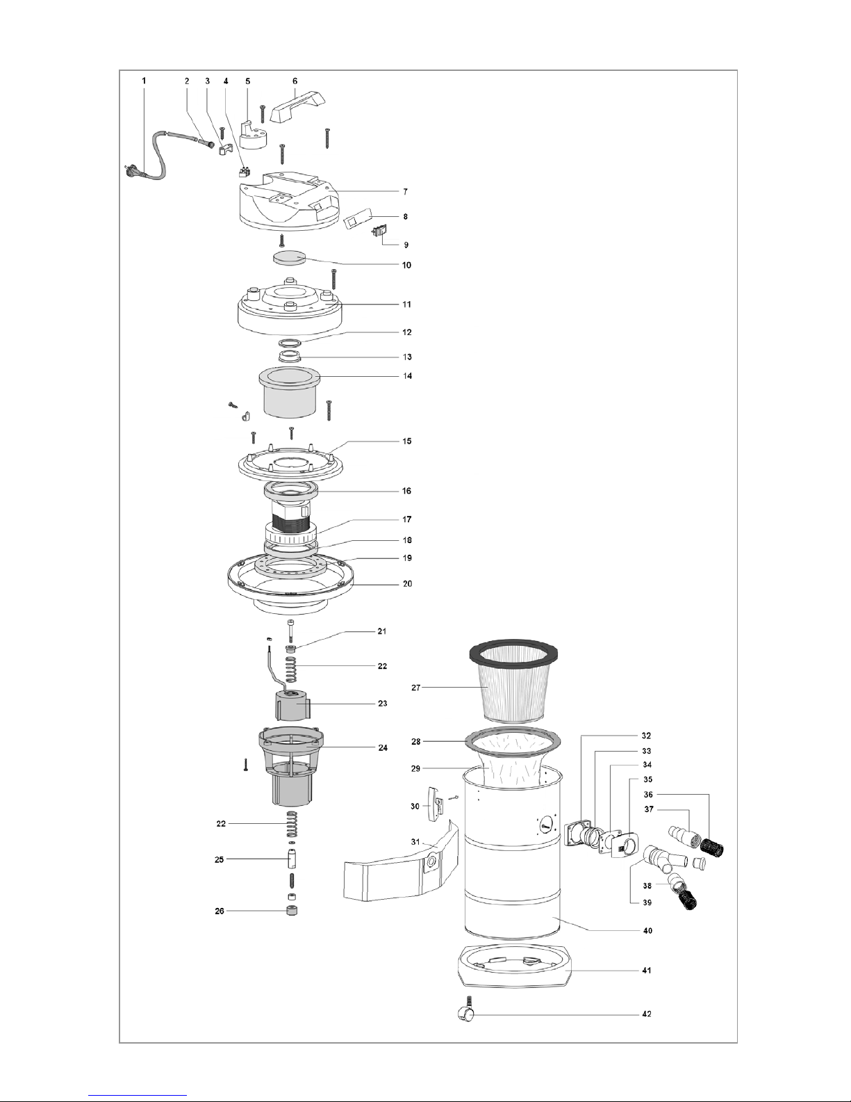
10. EXPLODED DRAWING AND SPARE-PART LIST
No. CODE DESCRIPTION
1 1501050 2x1 electric cable with plug
2 1501051 Fair-lead
3 1501052 Cable locking ring
4 1501053 Terminal board
5 1502021 Hook for cable
6 1502022 Handle
7 1502020 Cover
8 1501002 Brand label
9 1501013 Change over switch
10 1502023 Cover cap
11 1502024 Motor compartment cover
12 1502033 Spacer washer
13 1502034 Ring H = 7
14 1501032 Sound-absorbing filter
15 1502025 Motor support
16 1502035 Seal H = 5.5
17 1501015 Motor type BS280 1200W
18 1501016 Seal H = 16
19 1502036 MTP filter
20 1502026 Base with gasket
21 1502037 Spacer
22 1502038 Spring
23 1502039 Electromagnet
24 1502040 Body of filter shaking device
25 1502042 Piston
26 1502043 Rubber toecap
27 1501008 Filter cartridge
28 1502029 Filter cartridge support ring
29 1501010 Nylon filter bag
30 1502041 Plastic hook complete
31 1501101 Paper filter bag (pack of 10 pcs.)
32 1501037 Seal R205
33 1501038 Deflector
34 1501040 Seal D38
35 1501039 Filler
36 1501004 Suction pipe D. = 29 x L = 3m
37 1501006 Universal reduction sleeve
38 1501005 Sleeve for pipe D. = 29
39 1501003 Y-fitting with cap
40 1502030 PRO-3 Shake drum
41 1502031 Base for drum
42 1501054 Wheel
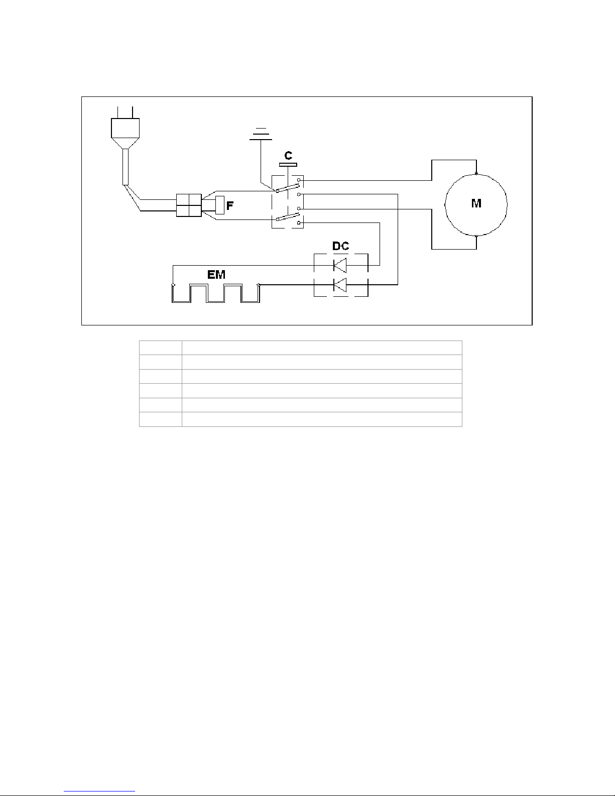
11. WIRING DIAGRAM
REF. DESCRIPTION
F Anti-jamming filter
C Change-over switch
M Motor
DC Rectifier board
EM Electromagnet

DENTALFARM s.r.l.
Via Susa, 9/a - 10138 TORINO - ITALY
TECHNICAL COMMERCIAL SERVICE - (+39) 011/4346588
TECHNICAL SUPPORT - 011/4346632
FAX 011/ 4346366
Website: www.dentalfarm.it
Table of contents


