Clayton WTP-107T-4 Guide

WARNING
Respiratory protection is recommended
operating this equipment.
WARNING
Eye protection is required when operating this
equipment.
WARNING
Hearing protection is recommended when
operating this equipment.
WARNING
Read and understand operator’s manual before
using this equipment.
SAFETY LEGEND
WARNING
WTP-4 August 03, 2021
Safety – Operation – Maintenance
Keep this document in a safe place
Read and understand this manual before operating your air tool
• A HEPA Filter must be installed in this vacuum at all times.
• If this vacuum is used to collect hazardous material, appropriate personal protective equipment may be required.
• Any alteration to this equipment by a third party will nullify its warranty.
WartHog WTP Power Head
Air Powered Industrial HEPA Vacuum with Pneumatic Tool Sync
Models: WTP-107T-4, WTP-115T-4, WTP-205T-4, WTP-215T-4
• Designed for toxic dust cleanup, housekeeping, and vacuum sanding
• Dry Recovery Only
Scan this QR code for
online instructions and
documentation, or visit
www.ClaytonHowTo.com
WTP-4_cover

TABLE OF CONTENTS
Repair or Warranty Contact Clayton Associates, Inc. • 1650 Oak Street • Lakewood, New Jersey 08701 • P.+1-732-363-2100 F.+1-732-364-6084
WTP-4 www.DustlessMadeSimple.com • [email protected]
Page 2
Applications & Environments...............................................................................................3
What’s In the Box ................................................................................................................3
............................................................................................3
Getting Started ....................................................................................................................4
Compressed Air Fittings ......................................................................................................6
Dynamic Power Control.......................................................................................................6
Pneumatic Tool Sync ...........................................................................................................7
Before Each Use .................................................................................................................8
Bag Filter Change................................................................................................................9
Safe Filter Change.............................................................................................................10
Pre‑Filter Change ..............................................................................................................11
HEPA Filter Change...........................................................................................................12
Illustrated Parts Breakdown...............................................................................................13
Limited Lifetime Warranty Terms And Conditions ..............................................................17
EC Declaration of Conformity............................................................................................18

Repair or Warranty Contact Clayton Associates, Inc. • 1650 Oak Street • Lakewood, New Jersey 08701 • P.+1-732-363-2100 F.+1-732-364-6084
WTP-4 www.DustlessMadeSimple.com • [email protected]
Page 3
• Designed for toxic dust cleanup, housekeeping, and vacuum sanding.
• Dry recovery only.
Do not use this equipment for cleaning or extracting fuel residues from any vehicle or equipment.
Do not use this equipment for cleaning or extracting live sparks or burning embers.
Do not use this equipment in combustible dust or gas atmospheres.
NOTE:
both a power head and an appropriate Clayton vacuum tank. Refer to the instruction manual included with the vacuum tank for
additional information.
PHYSICAL:
Weight....................................................................................................................................................................................TBD lbs (TBD kg)
Dimensions (Diameter x Height) .......................................................................................................................... 17.5 x 12 in (44.5 x 30.5 cm)
Sound Level........................................................................................................................................................................................... 67 dBA
POWER CONSUMPTION:
Pressure...................................................................................................................................................................................90 psi (621 kPa)
Flow .................................................................................................................................................................................60 CFM (102 SCMH)
FILTRATION:
...............................................................................................................................................
............................................................................................................................................................. 95% @ 0.5 micron
PERFORMANCE:
Poly Tank
Vacuum Flow.......................................................................................................................................................... 105 CFM (179 SCMH)
Vacuum Suction ..........................................................................................................................................................180 inH
2
O (45 kPa)
Steel Tank
Vacuum Flow.......................................................................................................................................................... 120 CFM (204 SCMH)
Vacuum Suction ..........................................................................................................................................................120 inH
2
O (30 kPa)
APPLICATIONS & ENVIRONMENTS
WHAT’S IN THE BOX
WTX-4_001
WartHog WTP Power Head
SPECIFICATIONS & REQUIREMENTS

Repair or Warranty Contact Clayton Associates, Inc. • 1650 Oak Street • Lakewood, New Jersey 08701 • P.+1-732-363-2100 F.+1-732-364-6084
WTP-4 www.DustlessMadeSimple.com • [email protected]
Page 4
1. The vacuum power head and the vacuum tank ship in separate boxes.
2. Unbox the vacuum power head.
3. Visually inspect the power head to verify that no parts are missing or damaged.
4. Familiarize yourself with the power head..
GETTING STARTED
Dynamic Power
Control
Compressed Air
Control Valve
Compressed Air
Coupler (Air Out)
WTP-4_002
Pneumatic Tool
Sync Gauge
Filter Adapter
Compressed Air
Plug (Air In)
HEPA Wire Lock
HEPA Wire Lock
Delay Valve
WTP-4_003

Repair or Warranty Contact Clayton Associates, Inc. • 1650 Oak Street • Lakewood, New Jersey 08701 • P.+1-732-363-2100 F.+1-732-364-6084
WTP-4 www.DustlessMadeSimple.com • [email protected]
Page 5
Prepare the vacuum for use.
1.
•
•
• Grasp the sides of the cardboard collar and push it all the way onto the inlet tube.
• Verify the bottom of the collar is past the opening on the underside of the inlet tube.
2.
• Remove the Clayton HEPA timer card from the box and set aside.
• Remove the HEPA cable lock from the box and set aside.
•
3.
•
•
–If it is not, rotate it clockwise until fully seated.
• Refer to the instructions included with the HEPA cable lock to install the cable lock.
4. Attach the power head.
• Position the power head on the tank.
• Rotate the power head so that the Compressed Air Control valve on the power
head is aligned with the inlet port on the vacuum tank.
• Latch the power head to the tank.
5.
• Attach the new HEPA timer card with a zip tie (included) to the top handle of the
vacuum.
• Follow the directions on timer card to activate it.
GETTING STARTED
GL_005
Filter Bag
Bottom and top of
Cardboard Bag Collar
Push Cardboard Bag Collar
past this point
Tank Wall
Tank Wall
WTP-4_004
Inlet Port
aligned with …
Compressed Air
Control Valve …

Repair or Warranty Contact Clayton Associates, Inc. • 1650 Oak Street • Lakewood, New Jersey 08701 • P.+1-732-363-2100 F.+1-732-364-6084
WTP-4 www.DustlessMadeSimple.com • [email protected]
Page 6
The vacuum has the following compressed air requirements to function properly:
• Compressed air must be clean, dry, and oil free to prevent blockage of the pneumatic system.
•
Compressed Air Plug (Air In)
•
•
•
• Install a new compressed air plug.
Compressed Air Coupler (Air Out)
•
• This coupler provides convenient pass through compressed air for an air tool connected to the vacuum.
•
•
• Install a new compressed air coupler.
Adjust the Dynamic Power Control (DPC)
•
•
• Do not force the rotation past these limits.
• Rotate the DPC clockwise to the fully‑closed position.
• Rotate the DPC counterclockwise 1 full turn to return to the factory setting.
•
• To decrease vacuum power and compressed air consumption, turn the DPC clockwise up to an additional 1/2 turn.
COMPRESSED AIR FITTINGS
DYNAMIC POWER CONTROL

Repair or Warranty Contact Clayton Associates, Inc. • 1650 Oak Street • Lakewood, New Jersey 08701 • P.+1-732-363-2100 F.+1-732-364-6084
WTP-4 www.DustlessMadeSimple.com • [email protected]
Page 7
Principle of Operation
Pneumatic Tool Sync senses the ow of compressed air to a connected tool and activates the vacuum.
• When the compressed air tool is activated, the compressed air line pressure opens a pneumatic valve which activates the power head.
• The auto system pressure in the valve should be approximately 90 psi while the tool is running.
•
Delay valve.
• When the tool sync pressure reaches approximately 15 psi the valve closes and deactivates the power head.
• The Tool Sync Pressure Gauge helps the user visualize the time delay by displaying the pressure in the pneumatic valve as it drops
from 90 psi to 0 psi.
Requirements
• A compressed air supply must be connected to the Compressed Air Plug (Air In) on the power head.
• The tool must draw its compressed air from a Compressed Air Coupler (Air Out) on the power head.
• Compressed air must be clean, dry, and oil free to prevent blockage of the pneumatic system.
•
1. Attach the compressed air line source to the vacuum.
• Verify the Compressed Air Control valve on the vacuum is in the AUTO/OFF position.
• Connect one end of the compressed air line to a compressed air source.
• Connect the other end of the compressed air line to the Compressed Air Plug (Air In) on the vacuum head.
2. Attach the compressed air tool.
• Insert the compressed air line plug into a Compressed Air Coupler (Air Out) on the power head.
the airline has been connected.
• Connect the compressed air line coupler to the tool’s compressed air plug/input.
3. Test Pneumatic Tool Sync.
• Rotate the Compressed Air Control valve on the vacuum to the AUTO/OFF position and activate the air tool.
• The power head will activate.
• Deactivate the air tool.
• The vacuum will deactivate after a short delay.
4.
The Shut O Delay is preset at the factory to approximately 5 seconds.
•
•
• Rotate the Compressed Air Control valve on the vacuum to the AUTO/OFF
position and activate the air tool.
• The vacuum will power on.
• Deactivate the air tool.
• The vacuum will remain running.
•
Gauge begins to drop.
• When the tool sync pressure reaches approximately 15 psi the pneumatic valve
deactivates the power head.
• Continue to test Pneumatic Tool Sync by activating the compressed air tool.
•
•
delay, tighten the jam nut by rotating it clockwise to lock the valve in place.
5. Multiple Tools
• Pneumatic Tool Sync will work with one or two tools simultaneously.
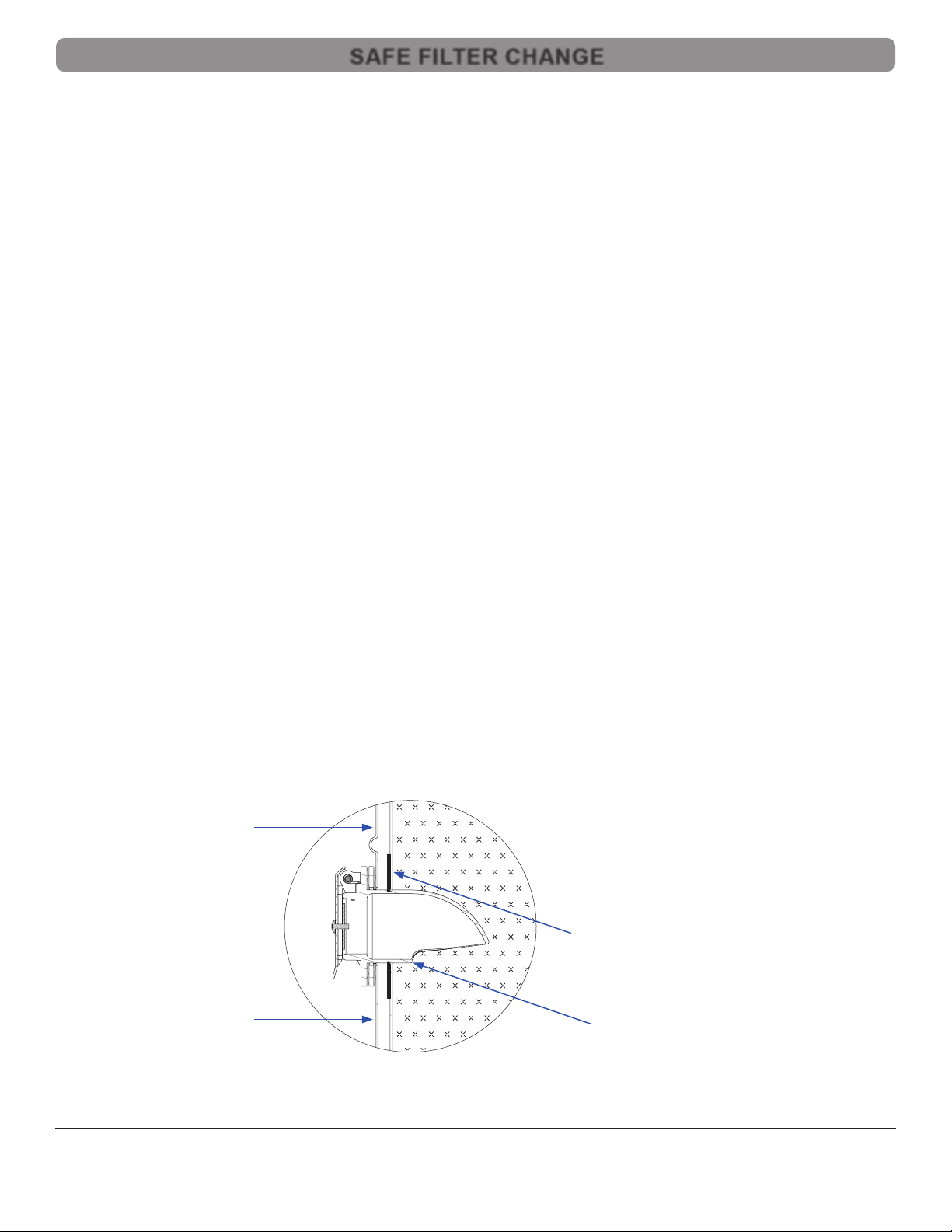
PNEUMATIC TOOL SYNC
GL_008
Jam Nut
Delay Valve

Repair or Warranty Contact Clayton Associates, Inc. • 1650 Oak Street • Lakewood, New Jersey 08701 • P.+1-732-363-2100 F.+1-732-364-6084
WTP-4 www.DustlessMadeSimple.com • [email protected]
Page 8
1. Connect the compressed air source.
• Verify the Compressed Air Control valve on the vacuum is in the AUTO/OFF position.
• Connect a compressed air line coupler to the Compressed Air Plug (Air In) on the power head.
• Connect the other end of the compressed air line to the compressed air source.
2. Attach a vacuum hose or combination air/vacuum work hose.
• Open the Inlet Port on the vacuum tank.
• Insert the metal sleeve of the vacuum hose into the Inlet Port on the vacuum tank.
3. Attach the compressed air output hose(s).
• When using a combination air/vacuum work hose, the compressed air output hose is part of the work hose assembly.
•
the airline has been connected.
4. Attach a tool.
•
been connected.
5. Activate the vacuum.
• Pneumatic Tool Sync Mode
air tool is activated.
–Rotate the Compressed Air Control valve to the AUTO/OFF position for Pneumatic Tool Sync.
•
to the ON position
–Rotate the Compressed Air Control valve to the ON position.
BEFORE EACH USE

Repair or Warranty Contact Clayton Associates, Inc. • 1650 Oak Street • Lakewood, New Jersey 08701 • P.+1-732-363-2100 F.+1-732-364-6084
WTP-4 www.DustlessMadeSimple.com • [email protected]
Page 9
1. Safe the vacuum.
• Verify the Compressed Air Control valve on the vacuum is in the AUTO/OFF position.
• Disconnect the vacuum from the compressed air source.
• Remove all tools and hoses from the vacuum.
2. Remove the power head.
• Unlatch the power head from the tank.
•
•
3.
•
• Holding your hand over the opening on the bag, lift the bag out of the tank.
• Dispose of the bag according to company policy.
4.
•
•
• Grasp the sides of the cardboard collar and push it all the way onto the inlet tube.
• Verify the bottom of the collar is past the opening on the underside of the inlet tube.
5.
•
•
–If it is not, rotate it clockwise until fully seated.
Replace the power head.
• Position the power head on the tank.
• Rotate the power head so the Compressed Air Control valve on the power head is aligned with the inlet port on the vacuum tank.
• Latch the power head to the tank.
BAG FILTER CHANGE
GL_005
Tank Wall
Tank Wall
Bottom and top of
cardboard bag collar
Push cardboard bag
collar past this point
Filter Bag

Repair or Warranty Contact Clayton Associates, Inc. • 1650 Oak Street • Lakewood, New Jersey 08701 • P.+1-732-363-2100 F.+1-732-364-6084
WTP-4 www.DustlessMadeSimple.com • [email protected]
Page 10
Principle of Operation
Safe Filter Change (SFC) uses a second Clayton HEPA vacuum and a Safe Filter Change Hose to create a downdraft within the primary
1. Connect the vacuums.
• Verify the Compressed Air Control valve on both vacuums is in the AUTO/OFF position.
• Remove all tools and vacuum hoses from the primary vacuum.
• Position the support vacuum with its inlet port facing the SFC port on the primary vacuum.
• Open the inlet port on the support vacuum.
• Insert one metal sleeve of the SFC hose into the inlet port on the support vacuum.
• Open the SFC port on the primary vacuum.
• Insert the other metal sleeve of the SFC hose into the SFC port on the primary vacuum.
• Connect both vacuums to a compressed air source.
2. Remove the power head.
• Unlatch the primary vacuum’s power head from its tank.
•
• Rotate the support vacuum’s Compressed Air Control valve to the ON position to create the downdraft.
•
•
• The primary power head should remain running.
3.
• Turn a large disposal bag inside out around your arms.
•
•
•
• Gather the neck of the disposal bag and seal the bag closed using tape or ties.
•
4.
•
•
• Grasp the sides of the cardboard collar and push it all the way onto the inlet tube.
• Verify the bottom of the collar is past the opening on the underside of the inlet tube.
continued on next page
SAFE FILTER CHANGE
GL_005
Filter Bag
Bottom and top of
Cardboard Bag Collar
Push Cardboard Bag Collar
past this point
Tank Wall
Tank Wall

Repair or Warranty Contact Clayton Associates, Inc. • 1650 Oak Street • Lakewood, New Jersey 08701 • P.+1-732-363-2100 F.+1-732-364-6084
WTP-4 www.DustlessMadeSimple.com • [email protected]
Page 11
5.
•
•
–If it is not, rotate it clockwise until fully seated.
Replace the primary power head.
• Carefully position the primary power head on the primary tank.
• Rotate the primary vacuum’s Compressed Air Control valve to the AUTO/OFF position.
• Rotate the power head until the Compressed Air Control valve is aligned with the inlet port on the vacuum tank.
• Latch the power head to the tank.
• Rotate the support vacuum’s Compressed Air Control valve to the AUTO/OFF position.
7. Disconnect the vacuums.
• Disconnect the SFC hose from the primary vacuum’s SFC port.
• Disconnect the SFC hose from the support vacuum’s inlet port.
1. Safe the vacuum.
• Verify the Compressed Air Control valve on the vacuum is in the AUTO/OFF position.
• Disconnect the vacuum from the compressed air source.
• Remove all tools and hoses from the vacuum.
2. Remove the power head.
• Unlatch the power head from the tank.
•
•
3.
•
• Find the seam and carefully peel the Velcro apart.
•
4.
•
•
•
5.
• Holding the power head on its side, examine the HEPA Filter.
•
–If it is not, rotate it clockwise until fully seated.
Replace the power head.
• Position the power head on the vacuum tank.
• Rotate the power head until the Compressed Air Control valve is aligned with the inlet port on the vacuum tank.
• Latch the power head to the tank.
SAFE FILTER CHANGE
PRE-FILTER CHANGE

Repair or Warranty Contact Clayton Associates, Inc. • 1650 Oak Street • Lakewood, New Jersey 08701 • P.+1-732-363-2100 F.+1-732-364-6084
WTP-4 www.DustlessMadeSimple.com • [email protected]
Page 12
Never attempt to clean
the HEPA lter as this will damage it.
1. Safe the vacuum.
• Verify the Compressed Air Control valve on the vacuum is in the AUTO/OFF position.
• Disconnect the vacuum from the compressed air source.
• Remove all tools and hoses from the vacuum.
2. Remove the power head.
• Unlatch the power head from the vacuum tank.
•
•
3.
• Remove the Clayton HEPA timer card from the box and set aside.
• Remove the HEPA cable lock from the box and set aside.
•
4.
• Holding the power head on its side cut the HEPA cable lock and remove it.
•
•
5. Install a new HEPA Filter
•
•
–If it is not, rotate it clockwise until fully seated.
• Refer to the instructions included with the HEPA cable lock to install the cable lock.
Replace the power head.
• Carefully position the power head on the vacuum tank.
• Rotate the power head until the Compressed Air Control valve is aligned with the inlet port on the vacuum tank.
• Latch the power head to the vacuum tank.
7.
• Remove the old HEPA timer card from the power head.
• Attach the new HEPA timer card with a zip tie (included) to the top handle of the vacuum.
• Follow the directions on the timer card to activate.
HEPA FILTER CHANGE

Repair or Warranty Contact Clayton Associates, Inc. • 1650 Oak Street • Lakewood, New Jersey 08701 • P.+1-732-363-2100 F.+1-732-364-6084
WTP-4 www.DustlessMadeSimple.com • [email protected]
Page 13
603-WTP-4 (Sheet 1 of 4)
ILLUSTRATED PARTS BREAKDOWN
Seq Item No Description
1 605-310A HH Vac Head Handle Cap SS Black
2 605-317E WTP Vac Enclosure Toxic Auto-Air Pneu SS Black
3 918-04BH Bulkhead Adapter, Brass, 1/4in.
4 918-08BH Bulkhead, 1/2 X 1/2, Brass
5 924-02BV3 Ball Valve 3-Way 1/8 FNPT
6 924-04CV Check Valve, 1/4 MNPT
7 924-04FC-01 Alpha Flow Control Valve
8 925-P24R160-01 Gauge Pressure 1.5in 0-160 psi Panel Mount
9 930-027 Handle, Carry, Flex Rubber
10 940-011 Fitting Coupler 1/4in Hiow X 1/4 MNPT
11 940-08PM FTG, Plug, 1/2 in MNPT
12 FE103212-HZSM-Z Hex Standoff, 10-32 MF X 3/4 in SS
13 NE10320608-HNSZ Nut 10-32 Nylon Lock SS Short
14 RE0620-SDSSS-Z Rivet Blind 3/16 X 0.625 Sealed SS (.251-.375)
15 SE103206-XPSM-Z Screw 10-32 X 3/8in SS TORX
16 WE133203-RFS-Z Washer .203ID X .500OD .047H Round Stainless Steel
WTX-4_005
1
6
11
2
7
12
13
14
15
16
3
8
4
9
5
10

ILLUSTRATED PARTS BREAKDOWN
Repair or Warranty Contact Clayton Associates, Inc. • 1650 Oak Street • Lakewood, New Jersey 08701 • P.+1-732-363-2100 F.+1-732-364-6084
WTP-4 www.DustlessMadeSimple.com • [email protected]
Page 14
ILLUSTRATED PARTS BREAKDOWN
603-WTP-4 (Sheet 2 of 4)
Seq Item No Description
1 600-A276T Auto System Flow Sensor Valve Threaded
2 922-T.25GN 1/4 in OD. Nylon Tubing Green
3 922-T.50NGE Tubing, 1/2 Polyethylene, Orange
4 922-T.50Y Tubing, Urethane, 1/2 in OD Yellow
5 924-08PV-01 Fabco Pancake Valve
6 927-04L-02 PC Elbow 1/8 MNPT X 1/4 Tube
7 927-04L-02F FTG Elbow 1/8 FNPT To 1/4 PC
8 927-04T Tee, 1/4 PC
9 927-08L-04 FTG Elbow 1/2 PC To 1/4 MNPT
10 927-08L-04F FTG Elbow 1/2PC To 1/4FNPT
Seq Item No Description
11 927-08L-08 FTG Elbow 1/2 PC To 1/2 MNPT
12 927-08MA-04 1/2 PC X 1/4 MPT Straight FTG
13 927-08MA-08 FTG, 1/2Tx1/2P Male Conn
14 927-08R04 FTG Reducer 1/2 MPC To 1/4 PC
15 927-08T FTG Union Tee 1/2 PC
16 927-08T-08 FTG Tee 1/2 PC To 1/2 MPT
17 927-08Y Union Y, 1/2PC
WTP-4_006
4
1
5
2
6
6
6
6
6
6
6
7
13
8
14
9
15
10
10
16
11
11
17
12
3
3

Repair or Warranty Contact Clayton Associates, Inc. • 1650 Oak Street • Lakewood, New Jersey 08701 • P.+1-732-363-2100 F.+1-732-364-6084
WTP-4 www.DustlessMadeSimple.com • [email protected]
Page 15
ILLUSTRATED PARTS BREAKDOWN
603-WTP-4 (Sheet 3 of 4)
Seq Item No Description
1 911-803-1 Handle Cap Sound Control Foam
2 911-803-3 Enclosure Top Sound Control Foam
3 911-803-4 Base Ring Sound Control Foam
4 911-803-6 Enclosure Foam 1 Sound Control
4 911-803-7 Enclosure Foam 2 Sound Control
4 911-803-8 Enclosure Foam 3 Sound Control
WTP-4_007
1
2
3
4

ILLUSTRATED PARTS BREAKDOWN
Repair or Warranty Contact Clayton Associates, Inc. • 1650 Oak Street • Lakewood, New Jersey 08701 • P.+1-732-363-2100 F.+1-732-364-6084
WTP-4 www.DustlessMadeSimple.com • [email protected]
Page 16
ILLUSTRATED PARTS BREAKDOWN
603-WTP-4 (Sheet 4 of 4)
Seq Item No Description
1 500-401-08 Flange Motor Adjustment For SuperHornet
2 600-019 Air Motor WartHog
3 600-WF-1364F Washer Fiber 13/64 ID X 3/8OD
4 601-021 Filter Adapter, WartHog
5 602-812 Can Plastic Mufer Black
6 605-310B16 HH Vac Head Base 16in SS Black
7 911-011 Gasket, Filter Adapter
8 911-12G22 Grommet, 3/4 X 1 3/8
9 911-812 Mufer Felt Kit For WartHog Air
10 FE103208-HZSM-B Hex Standoff, 10-32 MF X 1/2 SS With Bore
11 FE103212-HZSM-Z Hex Standoff, 10-32 MF X 3/4 in SS
12 FE103224-HZSM-Z Hex Standoff SS, 10-32 M-F X 1.5in Long
13 NE10320615-HNSZ Nut, 10-32 Nylon Lock, SS, High
14 SE103210-ACSM-L Screw 10-32 X 5/8 Low Socket Cap SS
15 SE103210-PFSM-Z Screw, FH100, SS, 1032 X .625
16 SE162012-XPSM-Z Screw 1/4-20 X 3/4in Button Head TORX SS
WTP-4_008
1
4
7
10
2
8
11
3
6
9
9
9
12
14
15
16
5
13

Repair or Warranty Contact Clayton Associates, Inc. • 1650 Oak Street • Lakewood, New Jersey 08701 • P.+1-732-363-2100 F.+1-732-364-6084
WTP-4 www.DustlessMadeSimple.com • [email protected]
Page 17
Warranty Terms
Clayton Associates, Inc. guarantees its manufactured products against defects in materials or workmanship and will either repair or replace
all parts that prove defective under normal use during the lifetime of the products. The warranty period shall commence from the date of paid
invoice.
This warranty does not cover (a) repairs due to normal wear, accident, neglect, misuse, or use other than as indicated in the instruction booklet
(b) products manufactured by third parties and distributed by Clayton (c) wear items such as bearings, rotor blades, regulators, valve stems,
levers, shrouds, guards, O‑rings, seals, gaskets, motor brushes, and other wearable parts.
Repair within the Continental US
associated with returning the products for repair to a Clayton selected service location and repair the product at no charge. Clayton personnel
will determine the best way to repair the product.
Past 90 days, Clayton will provide parts to the customer’s site at no charge or the customer may ship the product to a Clayton selected service
location at customer’s expense and Clayton will repair the product at no charge and provide return shipping.
Repair Outside the Continental US
Clayton will provide parts to the customer’s site at no charge or the customer may ship the product to a Clayton selected service location at
customer’s expense and Clayton will repair the product at no charge and provide return shipping.
Limitation of Liability
or its failure to operate.
Clayton Associates, Inc. makes no other warranty or representation of any kind, except that of title, and all other warranties, express or implied,
LIMITED LIFETIME WARRANTY TERMS AND CONDITIONS

Brad Clayton
President
Clayton Associates, Inc.
Place of Issue: Lakewood, New Jersey, USA November 23, 2018
Repair or Warranty Contact Clayton Associates, Inc. • 1650 Oak Street • Lakewood, New Jersey 08701 • P.+1-732-363-2100 F.+1-732-364-6084
WTP-4 www.DustlessMadeSimple.com • [email protected]
Page 18
Clayton Associates, Inc. of 1650 Oak Street, Lakewood New Jersey 08701 U.S.A. declare on our own responsibility that the
Industrial HEPA Filtered, Electrically Powered Vacuum Cleaners and Accessories for Dry Recovery
• Vacuum Models (where XXXX is the Tank Model):
WGX-XXXX-0, WGP-XXXX-0, WTX-XXXX-0, WTP-XXXX-0
WGX-XXXX-1, WGP-XXXX-1, WTX-XXXX-1, WTP-XXXX-1
• Tank Models: 115G,115T,205G, 205T, 215G, 215T
• With serial numbers ranging from WH0000001 through WH9999999
applicable directives:
•
• The Electromagnetic Compatibility Directive 2004/108/EC
Compliance has been obtained by application of the following standards:
• EN ISO 12100:2010-11
•
•
collection of hazardous dusts
• EN 55014-1:2017
• EN 55014-2:2015
Way, Wrexham Industrial Estate, Wrexham, LL13 9UZ, United Kingdom.
File Number: 18FILE0423
Subject to use for the purpose for which it was designed in accordance with relevant standards and with the manufacturer’s
EC DECLARATION OF CONFORMITY

Brad Clayton
President
Clayton Associates, Inc.
Place of Issue: Lakewood, New Jersey, USA November 23, 2018
EC DECLARATION OF CONFORMITY
Repair or Warranty Contact Clayton Associates, Inc. • 1650 Oak Street • Lakewood, New Jersey 08701 • P.+1-732-363-2100 F.+1-732-364-6084
WTP-4 www.DustlessMadeSimple.com • [email protected]
Page 19
Clayton Associates, Inc. of 1650 Oak Street, Lakewood New Jersey 08701 U.S.A. declare on our own responsibility that the
Industrial HEPA Filtered, Electrically Powered Vacuum Cleaners
• Vacuum Models (where XXXX is the Tank Model):
WGX-XXXX-0, WGP-XXXX-0, WTX-XXXX-0, WTP-XXXX-0
WGX-XXXX-1, WGP-XXXX-1, WTX-XXXX-1, WTP-XXXX-1
• Tank Models: 115G,115T,205G, 205T, 215G, 215T
• With serial numbers ranging from WH0000001 through WH9999999
Test Procedure:
• The test was performed using an aerosol generator and a photometer.
•
•
Test Results:
•
• Test performed at: 740 Driving Park Avenue, Rochester NY 14613 USA
Declaration:
•

Repair or Warranty Contact Clayton Associates, Inc. • 1650 Oak Street • Lakewood, New Jersey 08701 • P.+1-732-363-2100 F.+1-732-364-6084
www.DustlessMadeSimple.com • [email protected]
Clayton products are proudly made in the USA
This manual suits for next models
3
Table of contents
Other Clayton Vacuum Cleaner manuals

Clayton
Clayton BACKPACK HEPA Guide

Clayton
Clayton WGX-107G-0 Troubleshooting guide

Clayton
Clayton WartHog WTX-107T-0 Guide

Clayton
Clayton Warthog WGP Series Guide

Clayton
Clayton Warthog WTX Series Guide

Clayton
Clayton Scorpion SC-100 Series Guide

Clayton
Clayton WartHog 603-105G Guide

Clayton
Clayton WartHog Guide

Clayton
Clayton WartHog WGX Series Guide

Clayton
Clayton WH-105-0 User manual