Derale Perfomance 15551 User manual
15551-InstructionSheet
Derale Performance, Los Angeles, CA 800.421.6288 www.derale.com
INSTALLATION INSTRUCTIONS
ENGINE OIL COOLER KIT
PART # 15551
KIT CONTENTS
QTY. DESCRIPTION
1 Oil Cooler
1 Spin-On Adapter
1 Adapter Plate
1 Ports Up Filter Mount
1 O-ring (Spin-On Adapter)
1 O-ring (Adapter Plate)
1 Snap Ring
1 3/4-16 Filter Nipple
4 1/2” NPT x 1/2” Hose Barb
3 #14 Sheet Metal Screws
QTY. DESCRIPTION
1 3/4-16 Hex Sleeve Nut
1 13/16-16 Hex Sleeve Nut
1 18mm x 1.5 Hex Sleeve Nut
1 20mm x 1.5 Hex Sleeve Nut
1 22mm x 1.5 Hex Sleeve Nut
10ft 1/2” OEM Spec Hose
5 6” Zip Ties
6 Hose Clamps
4 Mounting Rods
4 Foam Pads
4 Mounting Clips
(Page 1)
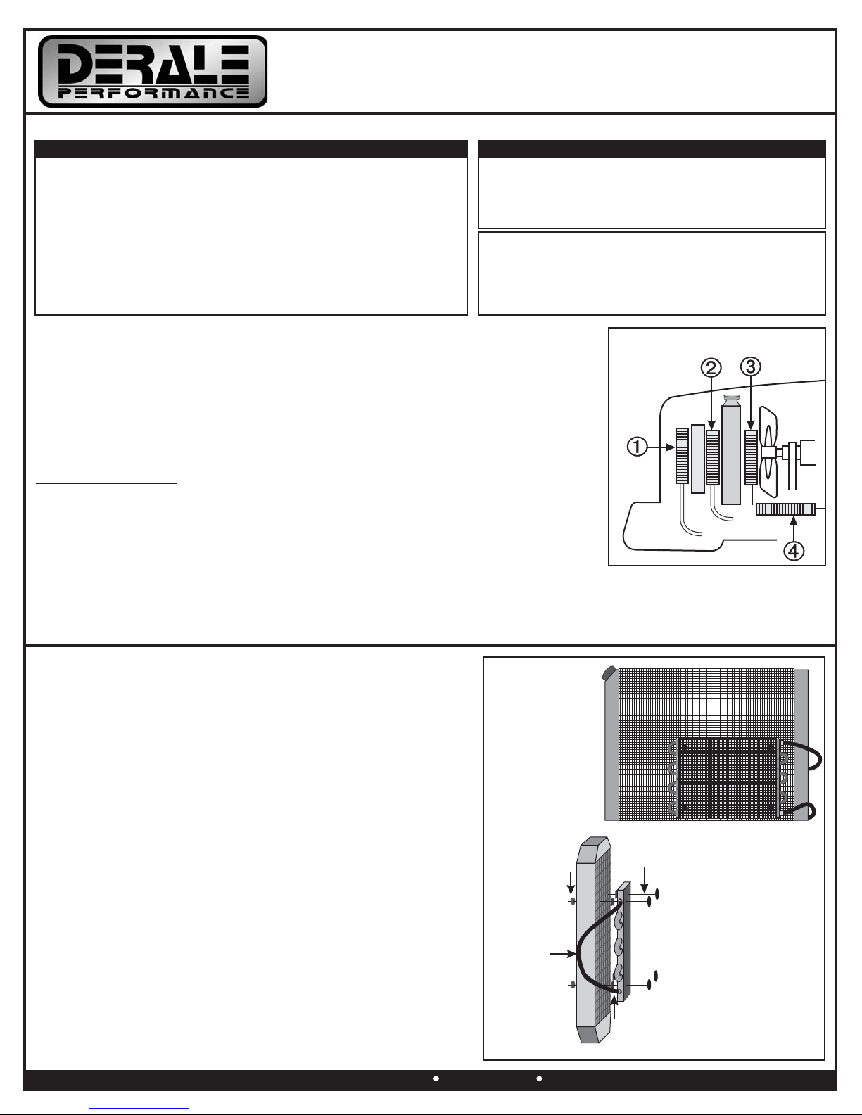
The Oil Cooler can be mounted in multiple locations on your vehicle. Reference Diagram # 1
for possible cooler positions. #1 is the ideal location, #2 is second best and #4 being the last
choice.
Note: The Cooler core will flow in either direction, there is no specified inlet or outlet port.
Diagram #1
TOOLS NEEDED
Standard Screw Driver or
5/16” Nut Driver
Dyke Pliers
Drill and 3/16” Bit
COOLER MOUNTING
(See Diagram #2)
1. Identify the 4 Mounting Rods, 4 Mounting Clips and
4 1x1 Foam Pads.
2. One by one, Install the 4 Mounting Rods thru the Transmission
Cooler.
3. Take the 1x1 Foam Pads supplied, peel off the paper lining & slide
them onto the Mounting Rods, sticking them against the
Transmission Cooler.
4. Take the Cooler Assembly with attached looped hose and hold in
the desired location.
5. Install the 4 Mounting Rods thru the Radiator/Condenser core.
Warning: Do not use excessive force when pushing the Mounting Rods
through the Radiator/Condenser. Excessive force could cause
damage to the fins and possibly puncture a tube.
6. Take the Mounting Clips supplied, making sure they are in the
correct direction (Derale writing out) install onto the Mounting Rods
and cinch them until the 1x1 Foam Pads are slightly compressed.
7. Cut off any excess Mounting Rods.
7/8” Open End Wrench
11/16” Open End Wrench
1 1/8” Socket
Thread Sealant Tape
Please read these instructions completely before starting the installation.
COOLER LOCATION
When selecting the best location for your vehicle, always consider a location that will
deliver the maximum airflow.
PRE-INSTALLATION
1. Identify the 1/2” NPT x 1/2” Barb Fittings.
2. Using Thread Sealant Tape or suitable sealant, install the two 1/2” NPT x 1/2” Barb Fittings
onto the Spin-On adapter, and two 1/2” NPT x 1/2” Barb Fittings onto the Ports Up filter mount.
3. Identify the 1/2” x 10ft. OEM Spec Hose and Hose Clamps.
4. Slide one hose clamp on each end of the supplied Hose.
5. Using a dab of oil lubricate each end of the hose and install hose onto the the cooler forming a
loop.
6. Secure in place using the Hose Clamps. (See Diagram #2)
Diagram #2
IMPORTANT
This kit is designed to fit vehicles with engine block oil
filter landings ranging from 2 1/2” to 3 1/2”, which
represents 90% of all vehicles.
Mounting
Rods
1x1
Foam Pads
Mounting
Clips
4’ Hose
Derale Performance, Los Angeles, CA 800.421.6288 www.derale.com
SELECTING COMPONENTS
To easily select the correct components for your application, follow the
steps below. Then proceed to the INSTALLATION section.
Selecting the Spin-on Adapter and/or Adapter Plate
1. Remove the factory oil filter from the vehicle.
2. Using a rag, clean the oil filter landing on the engine.
3. Take the supplied Spin-on Adapter and Adapter Plate.
4. To determine if your application uses the supplied Adapter Plate,
first hold the Adapter Plate up to the oil filter landing on the engine
block. The casting needs to seat directly onto the landing without
obstruction. If the Adapter Plate is too large, then disregard the
Adapter Plate and O-ring. (See Diagram #4)
5. Take the supplied Spin-On Adapter and hold it up the oil filter
landing on the engine block. The casting needs to seat directly onto
the landing without obstruction.
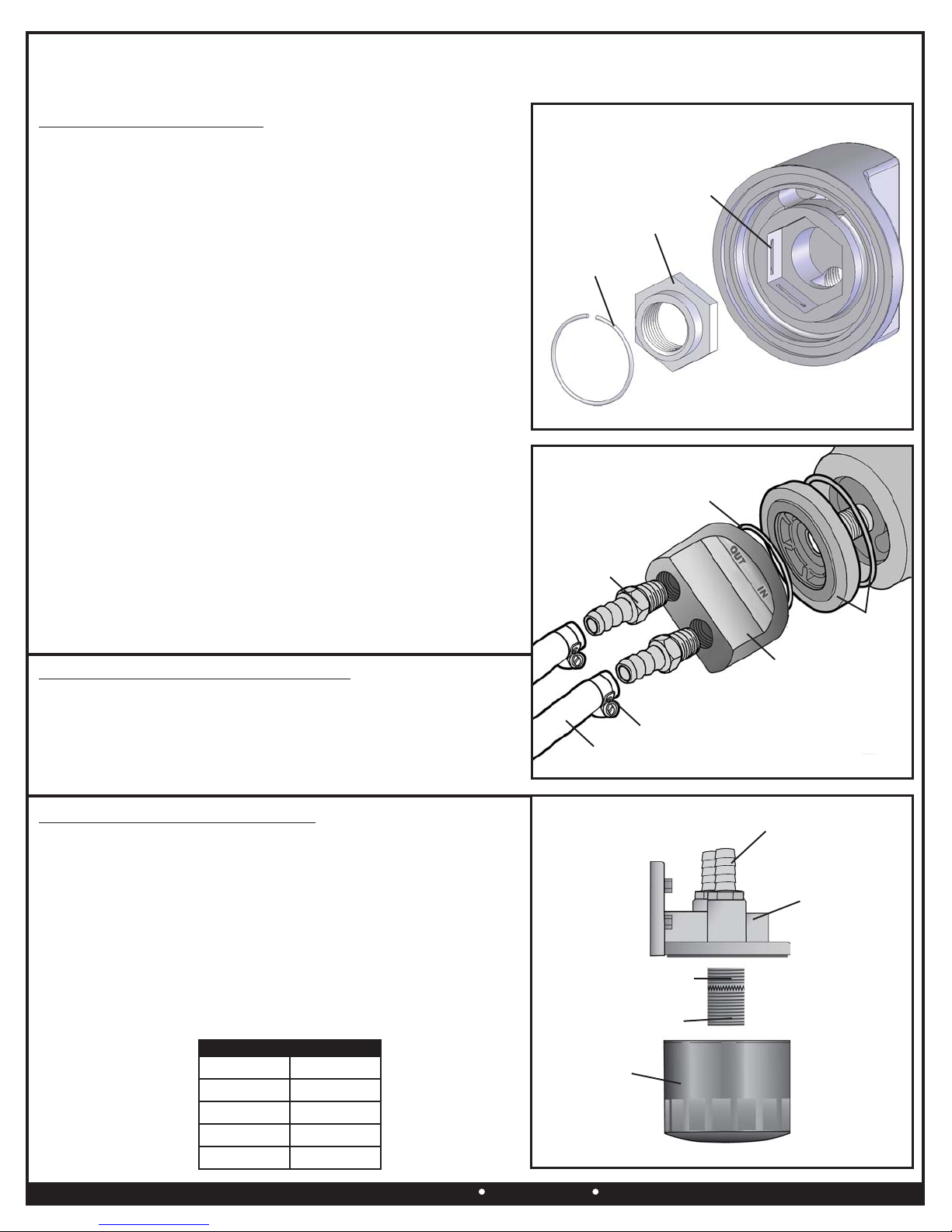
Selecting the Sleeve Nut
1. Take the 5 supplied Sleeve Nuts, try and screw each Sleeve Nut
onto the filter nipple on the engine block until the correct size will
completely thread onto the nipple. Once you have located the
correct Sleeve Nut, disregard the remaining 4 Sleeve Nuts.
2. Take the Sleeve Nut and slide it into the Spin-on Adapters hex
feature. Sleeve Nut will only install correctly in one direction.
(See Diagram #3)
3. Take the supplied Snap Ring and carefully install into the snap ring
groove of the casting making sure it is securely fastened.
(See Diagram #3)
Warning: It is recommended that you were the proper eye protection
when installing Snap Ring.
SPIN-ON ADAPTER INSTALLATION
1. Apply a light coat of oil onto the O-ring(s).
2. Take the O-ring and install into the groove on the Spin-On
Adapter and Adapter Plate (if used).
3. Install onto the engine. (See Diagram #4)
4. Hand Tighten with the same force used in tightening a factory oil filter.
(Page 2)
Important: The Adapter Plate & O-ring are designed to fit vehicles with a 3 1/2” filter landing. Primarily 1963-2007
GM SB & BB V-8 engines.
There are 5 supplied Sleeve Nuts in this kit. Only 1 Sleeve Nut will be used for your application.
Snap
Ring
Hex Sleeve
Nut
Snap Ring
Groove
Optional
Adapter Plate
& O-ring
Hose
Clamp
1/2” Hose
1/2” NPT x 1/2”
Hose Barb
Spin-On
Adapter
Spin-On
Adapter
O-ring
Diagram #4
Diagram #3
FILTER MOUNT INSTALLATION
1. Choose a convenient location for the Ports-Up Filter Mount. Make
sure there is enough space for future servicing of the oil filter.
Suggested Locations: Firewall, Radiator Support, Fender well.
2. Take the 3/4-16 Filter Nipple supplied, making sure the shorter end
of threads is installed onto the Ports-Up Filter Mount.
(See Diagram #5)
3. Using the filter mount as a template, mark and drill three 3/16” holes.
4. Using the #14 Sheet Metal Screws provided, install the Ports-Up
Filter Mount onto the vehicle.
Important: The new Filter Mount is designed to accept a 3/4-16 oil
filter Use Derale Part # 13092 or reference chart below for.
manufacturers part numbers.
Diagram #5
Oil Filter
3/4-16
Filter Nipple
Filter Mount
Short End Screws
into Filter Mount
1/2” NPT x 1/2”
Hose Barb
BRAND
AC
Fram
Motorcraft
Purolator
PART #
PF2
PH8A
FL1A
PER1A
OIL FILTER CHART

Derale Performance, Los Angeles, CA 800.421.6288 www.derale.com
VEHICLE TESTING
1. Start the engine and quickly check all connections for leaks.
2. Turn-off the engine and check oil level.
3. Add oil as needed.
ROUTING HOSES
Note: The Cooler core will flow in either direction; there is no specified inlet or outlet port.
Important: The oil flow direction should go in the following order: Engine, Ports Up Filter Mount, Oil Cooler, and then back to the
Engine. (See Diagram #6)
1. Using the remaining four Hose Clamps supplied, route the looped hose from the Oil Cooler along the frame toward the Ports
Up Filter Mount and/or the Spin-on Adapter.
Note: When routing hoses, be sure to keep all hoses away from sharp edges, moving parts and hot engine components. Hoses
should be routed carefully and should not be bent in less than a 5” radius.
2. Attach either hose coming from the Oil Cooler to the “OUT” port on the Ports Up Filter Mount.
3. Attach the remaining hose on the Oil Cooler to the “IN” port on the Spin-on Adapter.
4. Attach a hose from the “OUT” port on the Spin-on Adapter to the “IN” port on the Ports Up Filter Mount.
5. Apply a light coat of oil onto the O-ring of your new oil filter and install on the Ports Up Filter Mount.
Warning: Installation of accessories should only be undertaken by those with mechanical knowledge and are familiar with working on
vehicles. Always use eye protection (goggles, safety glasses or shield). Park the vehicle in a well lit area, on level ground and apply the
parking brake. Only work on a cold vehicle that has been sitting overnight, failure to do so will result in severe burns and injury. Before starting
the vehicle, make sure no tools or any other items are left under hood that could interfere with or be drawn into moving parts of the engine.
Failure to follow instructions can lead to severe damage and personal injury.
(Page 3)
Spin-On
Adapter
Ports Up
Filter Mount
Oil
Cooler
Fire Wall
Diagram #6


