manuals.online logo
Brands
  1. Home
  2. •
  3. Brands
  4. •
  5. Dodge
  6. •
  7. Automobile Part
  8. •
  9. Dodge Para-Flex GT User manual

Dodge Para-Flex GT User manual

Because of the possible Danger to persons or property from accidents which may result from the improper use of products, it is important that correct procedures be followed: Products must be used in
accordance with the engineering information specified in the catalog. Proper installation, maintenance and operational procedures must be observed. The instructions in the instruction manual must be
followed. Inspections should be made as necessary to assure safe operation under prevailing conditions. Proper guards and other suitable safety devices or procedures as may be desirable or as may
installed, adjusted and maintained by qualified personnel who are familiar with the construction and operation of all equipment in the system and the potential hazards involved. When risk to persons or
property may be involved, a holding device must be an integral part of the driven equipment beyond the speed reducer and output shaft.
Instruction Manual for DODGE Para-Flex GT, GTL, and GFB
To ensure that the drive is not unexpectedly started, turn off, lock out, and tag power source before proceeding. Failure to observe these precautions could
result in bodily injury.
Install in the following sequence:
(1) Inspect the shaft to ensure that it is smooth, straight and within commercial shaft tolerances as found in Table 1. Inspect the coupling hub to
ensure that the adapter and hub have not been damaged during shipping or storage.
(2) Remove any anti-rust lubricants or oil from the shaft. If necessary, clean shaft end
and shaft seat beneath coupling lightly with emery paper.
(3) Check the axial float of the shafts. Position the shafts at the mid-point of the float.
Where limited end float is required or sleeve bearings are used, consult DODGE for
application assistance at 864-284-5700.
(4) Referring to Figure 1 and Table 2, observe the “B” dimension for the coupling size
being installed. Mount and position the flanges on the shafts so that dimension “B”
is achieved when the shafts are in their final position.
(5) For Straight bore hubs mount the hub assembly per “Section 1 – Straight Bore Hub Installation” found below. For Taper-Lock bushings/hubs
mount the hub assembly per “Section 2 – Taper-Lock Hub Installation” found below. For Grip-Tight hubs/adaptors, mount the assembly per
“Section 3 – Grip-Tight Hub Installation” found below.
(6) Align flanges using precision equipment such as dial indicators or laser equipment. If precision equipment is not
available, scales, straight edges, and calipers can be used as less accurate means of alignment. To achieve
maximum coupling performance, align the coupling as accurately as possible during installation.
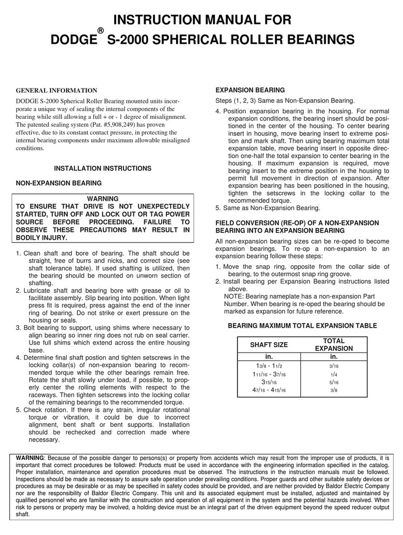
Section 1 – Straight Bore Hub Installation
Figure 1: PXGFB Assembly
Tighten set screws to torque values given in Table 3. (Note: Set screws are located on coupling hub beneath clamp ring, and must be tightened
prior to installing the flexible element.)
Table 3
Series Set Screw Torque (in-lb)
50 87
60 87
80 290
Section 1a-Straight Bore Uninstallation
(1) Loosen set screws. (Note: Set screws are located on coupling hub beneath clamp ring, and must be loosened after uninstalling flexible element
.)
(2) Slide coupling hub off of shaft.
Table 1 – Shaft Tolerances
Shaft Size
(Inches)
Recommended Shaft Tolerances
(Inches)
Up to 1-1/2” +0.000 / -0.002
1-5/8” – 2-1/2” +0.000 / -0.003
2-11/16” – 3” +0.000 / -0.004
Table 2
Size “B” Dimension
50 0.97
60 1.28
80 1.50
External Clam
p
Rin
g
Locknu
t
Hex-Head Micro-
Mount Screw
Elastomeric Elemen
t
Hub
Lockwashe
r
Slide coupling hub onto shaft so that the hub and end of the shaft are even.(1)
(2)
WARNING
WARNING
Baldor Electric Company
. This unit and its associated equipment must bebe specified in safety codes should be provided, and are neither provided by nor are the responsibility of
Baldor Electric Company
Section 2 - Taper-Lock Hub Installation
Figure 2: PXGTL Assembly
(1) Insert bushing into hub. Match the hole pattern, not threaded holes (each complete hole will be threaded on one side only).
(2) Lightly oil setscrews and thread into those half-threaded holes with the threads in the hub. Do not lubricate the bushing taper, bushing bore, hub
taper or shaft. Doing so could be harmful to the product.
(3) Position assembly onto shaft allowing for mild axial movement of hub that will occur during tightening procedure.
(4) Alternately torque setscrews to recommended torque setting as shown in Table 4 below. Be careful to avoid using worn hex key wrenches as they
tend to result in a loose assembly or may damage the setscrews.
Table 4
Series Bushing Wrench Torque
(in-lb)
50 1215 175
60 2012 280
80 2517 430
(5) To increase gripping force, hammer face of bushing using a brass drift or sleeve. Do not hit bushing directly with hammer.
(6) Re-torque screws after hammering.
Section 2a – Dismounting Taperlock Bushing Assembly
(1) Remove all setscrews.
(2) Insert one setscrew into any half-threaded hole that is threaded on the bushing.
(3) Loosen bushing by tightening the setscrew.
Hex-Head Micro-
Mount Screw
Lockwasher
Locknut
External Clamp Ring
Hub
Elastomeric Element
Taper-Lock
Bushing
Because of the possible Danger to persons or property from accidents which may result from the improper use of products, it is important that correct procedures be followed: Products must be used in
accordance with the engineering information specified in the catalog. Proper installation, maintenance and operational procedures must be observed. The instructions in the instruction manual must be
followed. Inspections should be made as necessary to assure safe operation under prevailing conditions. Proper guards and other suitable safety devices or procedures as may be desirable or as may
installed, adjusted and maintained by qualified personnel who are familiar with the construction and operation of all equipment in the system and the potential hazards involved. When risk to persons or
property may be involved, a holding device must be an integral part of the driven equipment beyond the speed reducer and output shaft.
WARNING
Baldor Electric Company
. This unit and its associated equipment must bebe specified in safety codes should be provided, and are neither provided by nor are the responsibility of
Baldor Electric Company
Section 3 - Grip-Tight Hub Installation
The DODGE Grip-Tight adapter mounted Para-Flex coupling incorporates a unique way of mounting and dismounting a coupling to and from the shaft. The patented
feature pushes the coupling hub onto the tapered adapter sleeve and locks it into place as the locknut is given a predetermined clockwise rotation. The locknut pushes
against the coupling hub face ensuring a positive uniform engagement of the coupling hub and adapter. Dismounting is accomplished by rotating the locknut in a
counter-clockwise direction pulling the coupling from the adapter and releasing it from the shaft.
Figure 3: PXGT Assembly
(1) Place the locknut into the groove on the coupling hub, THEN insert the adapter sleeve into the coupling hub in the direction of the taper. Rotate the locknut
clockwise to engage the adapter sleeve.
(2) Do not use lubricants on the shaft or any surfaces of the coupling assembly.
(3) Slide the hub assembly into position onto the shaft. If the unit will not slip onto the shaft, turn locknut counter-clockwise to expand adapter sleeve.
(4) Wearing gloves, rotate locknut clockwise, by hand, as tight as possible until the adapter sleeve grips and does not spin on the shaft. If needed, tap on the
locknut outer diameter while turning locknut to assist with this step. At this point you should not be able to rotate the locknut by hand and you should not be
able to move the hub assembly axially along the shaft by hand. If the hub assembly can be moved axially along the shaft then continue tightening the locknut
until assembly is unable to move axially by hand.
(5)
(6) Lock hub assembly to shaft by rotating locknut, with a spanner wrench or brass drift and hammer, clockwise by amount shown in Table 5.
(7) Tighten locknut setscrew until 3/32” Allen key bends (25 in-lbs).
Section 3a – Dismounting GT Adapter Assembly
(1) Completely remove the setscrew in the adapter locknut.
(2) Rotate the locknut counter-clockwise with a spanner wrench or brass drift pin and hammer.
(3) The locknut will alternate between spinning easily and becoming snug. When the locknut becomes snug strike, while rotating counter-clockwise,
the backside of the flange with a soft mallet around the entire face as shown to reduce resistance.
(4) Repeat steps 2 and 3 until flange assembly becomes loose.
Table 5
Series Locknut Rotation
50 2/3 Turn
60 1 Turn
80 1 Turn
Clamp Ring
Coupling Hub
Elastomeric Element
Hex-Head Micro-
Mount Screw
Tapered Adaptor Sleeve
Grip Tight Locknut
Locknu
t
Lockwashe
r
Scribe a line on the locknut above the adapter sleeve slot. This scribe line will be used in step 5 to verify proper locknut rotation.
Because of the possible Danger to persons or property from accidents which may result from the improper use of products, it is important that correct procedures be followed: Products must be used in
accordance with the engineering information specified in the catalog. Proper installation, maintenance and operational procedures must be observed. The instructions in the instruction manual must be
followed. Inspections should be made as necessary to assure safe operation under prevailing conditions. Proper guards and other suitable safety devices or procedures as may be desirable or as may
installed, adjusted and maintained by qualified personnel who are familiar with the construction and operation of all equipment in the system and the potential hazards involved. When risk to persons or
property may be involved, a holding device must be an integral part of the driven equipment beyond the speed reducer and output shaft.
WARNING
Baldor Electric Company
. This unit and its associated equipment must bebe specified in safety codes should be provided, and are neither provided by nor are the responsibility of
Baldor Electric Company
Section 4 – Flexible Element Installation
(1) If flanges are being re-used, clean flange mounting area as well as flexible element seats with a solvent, such as Xylene (Xylol), to remove
grease, oil, and dirt from surfaces. A diluted soapy water solution may be applied to aid with element installation.
(2) Loosen clamp ring nut so the element toe can seat within the clamp ring faces. Wrap flexible element around flanges as shown. Make sure the toe
of the element is fully worked down into the flange and seats on the hub. To ensure proper seating, rap around the tire’s outside diameter with a
small mallet until split is closed. Make sure element is evenly centered on the flanges.
(3) Hold split closed and tighten clamp ring nuts by hand. Using both hands, knead the tire pulling it toward the split and tighten clamp ring nuts
further to hand-tight.
(4) Tighten hex-head micro-mount screws to the torque shown in Table 6.
NOTE: The bottom of the hex-head cap screws should compress the lockwasher beneath the head. If the lockwasher is not compressed then the
locknuts should be loosened 1/8 turn. To accomplish this, loosen hex-head cap screws and rotate locknut(s) 1/8 turn in the counterclockwise
direction. Repeat item 4 above.
Table 6
Micro-mount Screw
Size Size Torque
50 M6 x 18mm 130 in-lbs
60 1/4-20 x 7/8 140 in-lbs
80 5/16-18 x 1-1/8 290 in-lbs
Section 4a – Flexible Element Replacement
(1) Loosen hex-head micro mount screws.
(2) Loosen clamp ring nuts by rotating counter clockwise.
(3) Grasp one end of flexible element at the split and peel it off the flanges.
(4) Clean clamping parts with a solvent, such as Xylene (Xylol), to remove grease, oil, wax and dirt from surfaces.
(5) Realign coupling and install new flexible element according to Section 4.
IM499389
www.baldor.com www.ptplace.com www.dodge-pt.com www.reliance.com
Baldor Electric Company Headquarters

P.O. Box 2400, Fort Smith, AR 72902-2400 U.S.A., Ph: (1) 479.648.5792, Fax (1) 479.648.5792, International Fax (1) 479.648.5895
Baldor - DODGE/Reliance
6040 Ponders Court, Greenville, SC 29615-4617 U.S.A., Ph: (1) 864.297.4800, FAX: (1) 864.281.2433
5/07 Copyright © 2007 Baldor Electric Company All Rights Reserved. Printed in USA. This material is not intended to provide operational instructions. Appropriate instruction manuals and precautions
should be studied prior to installation, operation or maintenance of equipment.

This manual suits for next models

2

Other Dodge Automobile Part manuals

Dodge 8W-43 Quick start guide

Dodge

Dodge 8W-43 Quick start guide

Dodge 8W-49 Quick start guide

Dodge

Dodge 8W-49 Quick start guide

Dodge 8W-97 Operating and installation instructions

Dodge

Dodge 8W-97 Operating and installation instructions

Dodge 8W-15 Quick start guide

Dodge

Dodge 8W-15 Quick start guide

Dodge 2000 DURANGO User manual

Dodge

Dodge 2000 DURANGO User manual

Dodge 8W-35 Quick start guide

Dodge

Dodge 8W-35 Quick start guide

Dodge 8W-56 Quick start guide

Dodge

Dodge 8W-56 Quick start guide

Dodge S-2000 User manual

Dodge

Dodge S-2000 User manual

Dodge 8W-40 Quick start guide

Dodge

Dodge 8W-40 Quick start guide

Popular Automobile Part manuals by other brands

Riello R40 F3 installation instructions

Riello

Riello R40 F3 installation instructions

Holley Carburetor none installation instructions

Holley

Holley Carburetor none installation instructions

ICON 51200 instructions

ICON

ICON 51200 instructions

Edelbrock 63-0144 installation instructions

Edelbrock

Edelbrock 63-0144 installation instructions

Toyota TUNDRA 2004 Technical service bulletin

Toyota

Toyota TUNDRA 2004 Technical service bulletin

Briggs & Stratton 31H700 Series Illustrated parts list

Briggs & Stratton

Briggs & Stratton 31H700 Series Illustrated parts list

Edelbrock 72310 installation instructions

Edelbrock

Edelbrock 72310 installation instructions

BENDIX SINGLE ANCHOR PIN CAM BRAKE General description

BENDIX

BENDIX SINGLE ANCHOR PIN CAM BRAKE General description

Edelbrock Harley Nitrous Systems 63-0052 installation instructions

Edelbrock

Edelbrock Harley Nitrous Systems 63-0052 installation instructions

Tomei ARMS MX8280 4B11 installation manual

Tomei

Tomei ARMS MX8280 4B11 installation manual

Edelbrock E-Force 1580 installation instructions

Edelbrock

Edelbrock E-Force 1580 installation instructions

Harbor Freight Tools Pittsburgh Automotive 95553 user manual

Harbor Freight Tools

Harbor Freight Tools Pittsburgh Automotive 95553 user manual

Restomod Air Quantum instructions

Restomod Air

Restomod Air Quantum instructions

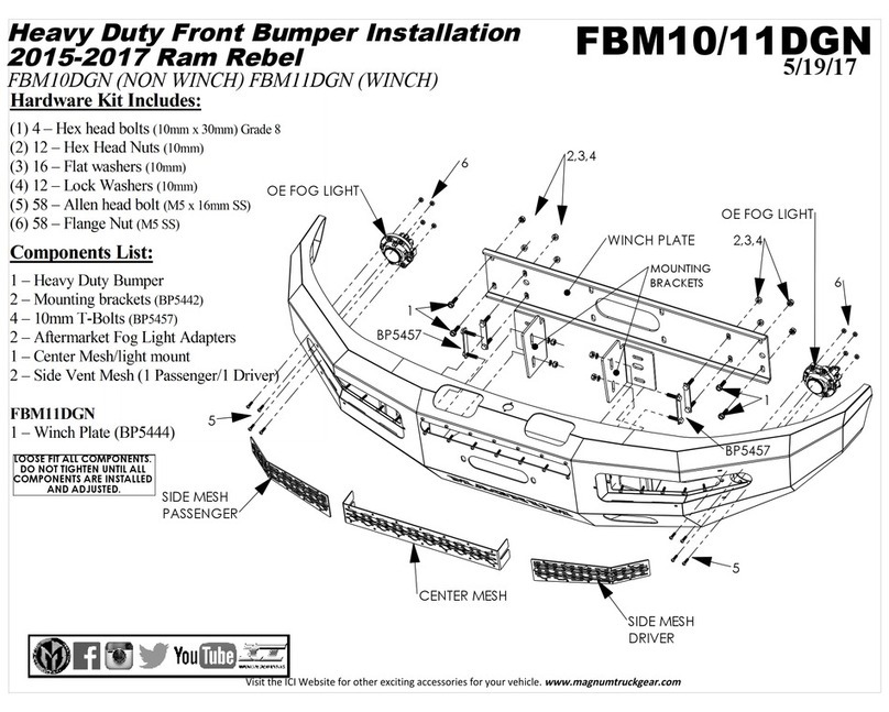
ICI Magnum FBM10DGN Installation

ICI

ICI Magnum FBM10DGN Installation

Havis-Shields Rear Partition w/ Exit Hatch P-REAR-2 installation instructions

Havis-Shields

Havis-Shields Rear Partition w/ Exit Hatch P-REAR-2 installation instructions

Edelbrock 90 V6 200 installation instructions

Edelbrock

Edelbrock 90 V6 200 installation instructions

Edelbrock Performer 70011 Information guide

Edelbrock

Edelbrock Performer 70011 Information guide

MICO Lock System 691 Operation and installation instructions

MICO

MICO Lock System 691 Operation and installation instructions

manuals.online logo
manuals.online logoBrands
  • About & Mission
  • Contact us
  • Privacy Policy
  • Terms and Conditions

Copyright 2025 Manuals.Online. All Rights Reserved.