Derbi ATV DXR 200 Instruction manual

ATV DXR 200
WORKSHOP MANUAL

1
The work-shop (or service) manual is mainly for NACIANAL MOTOR, S.A.U. Area importers and their net-
work dealers & service stations to fulfill the necessary maintenance and repairs information.
1. Due to continuous launch of new models, formation in this manual may be subject to change without
notice. For any further information regarding this manual or the products, please contact the Territorial
Distributor or Area Importer.
2. All details of this manual are based on the latest product information available at the time of approval
for printing. Maker reserves the right to make changes at any time without notice and without incurring any
obligation.
3. This manual has been specially prepared to provide the necessary information for the Area importer,
dealers, and their qualified mechanics of proper maintenance and repair details.
4. This manual covers all series of products (RAM 125/150) that user has to find out what details belong to.
By: Sales and Service Department NACIANAL MOTOR, S.A.U.
* The images reflected in this manual can vary of the acquired pattern.
For Area Importer and Territorial Distributor:
* All rights reserved. No part of this manual may be reproduced or unauthorized use in any form or by any
means, without prior permission of the Maker, NACIONAL MOTORS. S.A.U.
http: www.derbi.com
NACIONAL MOTOR, S.A.U.


3
PART 1. GENERAL INFORMATION
l-0l. Service Precautions
1-02.Briefing Service Information
1-03.Cleaning
1-04.Storage
PART 2. SPECIFICATION
2-01.General Specification
2-02.Location & Cable Routing
2-03.Torque Value
2-04.Special Tools -- OPTION (reference)
PART 3. PERIODIC MAINTENANCE AND ADJUSTMENT
3-01.Caution of periodic maintenance
3-02.Owner’s manual and tool kit
3-03.Periodic maintenance table
3-04.Engine oil (4-stroke)
3-05.Spark plug inspection
3-06.Air cleaner cleaning
3-07.Idle speed adjustment
3-08.Throttle lever adjustment
3-09.Speed limited adjustment
3-10.Front drum brake inspection
3-11.Rear disc brake - fluid inspection
3-12.Front brake lever free play adjustment
3-13.Parking brake adjustment
3-14.Clutch adjustment
3-15.Drive chain slack check and adjustment
3-16.Cable inspection and lubrication
3-17.Upper and lower arm pivot lubrication
3-18.Steering shaft inspection & lubrication
3-19.Ton-in adjustment
3-20.Front shock absorber adjustment
Pág. 9
Pág. 11
Pág. 12
Pág. 13
Pàg. 14
Pág. 16
Pág. 19
Pág. 21
Pág. 23
Pág. 23
Pág. 24
Pág. 26
Pág. 28
Pág. 29
Pág. 31
Pág. 31
Pág. 31
Pág. 31
Pág. 31
Pág. 33
Pág. 33
Pág. 35
Pág. 35
Pág. 37
Pág. 37
Pág. 37
Pág. 39
Pág. 39

4
3-21.Rear shock absorber adjustment -- option
3-22.Tire inspection
3-23.Tire wear limit
3-24.Wheel removal and installation
3-25.Replacing the headlight
3-26.Replacing the rear-light
3-27.Battery charging system
3-28.Battery removal
3-29.Fuse
3-30.Fuel tank
3-31.Engine Adjustment
PART 4. ENGINE DETAILS
4-01.Fuel System and Carburetion
4-02.Lubrication System
4-03.Engine Removal/Installation
4-04.Cylinder Head/Valve
4-05.Cylinder/Piston
4-06.Starter/Generator/L Crankcase/Start Clutch/Camshaft
4-07.Clutch/Gear Shift Mechanism
4-08.Crankcase/Crankshaft/Transmission/Starter Spindle
PART 5. CHASSIS DETAILS
5-01.Front Wheel/Front Brake
5-02.Rear Wheel/Rear Axle
5-03.Rear Brake
5-04.Steeling System
5-05.Front Shock Absorber and Front Arm
5-06.Rear Shock Absorber and Swing-Arm
5-07.Drive Chain and Sprocket
Pág. 39
Pág. 41
Pág. 42
Pág. 43
Pág. 43
Pàg. 43
Pág. 43
Pág. 45
Pág. 45
Pág. 45
Pág. 47
Pág. 52
Pág. 57
Pág. 61
Pág. 65
Pág. 73
Pág. 81
Pág. 87
Pág. 93
Pág. 104
Pág. 111
Pág. 119
Pág. 123
Pág. 130
Pág. 136
Pág. 143

5
PART 6. ELECTRIC DETAILS
6-01.Service Precautions(Electric Devices)
6-02.Ignition System
6-03.Charging System
6-04.Starting System
6-05.Lights/Instruments/Switches
PART 7. TROUBLE-SHOOTING
7-01.Engine does not start or hard to start
7-02.Poor performance (especially at low and idle speed)
7-03.Poor performance (engine lacks power)
7-04.Poor performance (at high speed)
7-05.Poor charging (battery over discharge or overcharge)
7-06.Spark plug has no function
7-07.F. or R. Brake Performance Poorly
7-08.Shock Absorber Malfunction
7-09.Instable Handling
PART 8. APPENDIX:
8-01.Notes of Pre-Delivery Inspection
8-02.UPDATE information - 170cc & BLAST model
8-03.UPDATE information - EEC 92\61 On Road Model
Pág. 149
Pág. 153
Pág. 159
Pág. 165
Pág. 171
Pàg. 179
Pág. 180
Pág. 181
Pág. 184
Pág. 185
Pág. 186
Pág. 187
Pág. 187
Pág. 188
Pág. 189
Pág. 191
Pág. 192

6
1-1 IMPORTANT SAFETY MESSAGE
BE SURE TO INFORM THE END-USER FOLLOWS;
1 . TO READ THE OWNER MANUAL CAREFULLY AND COMPLETELY BEFORE OPERATING THE ATV. . MAKE
SURE THE END-USER UNDERSTAND ALL INSTRUCTIONS.
2. PAY ATTENTION TO THE WARNING AND CAUTION. LABELS ON THE ATV.
3. ANY ATV OVER 90cc SHOULD NOT BE RIDDEN BY ANYONE UNDER 16 YEARS OF AGE. (or REFER THE
LOCAL RIDING LAWS AND REGULATIONS)
1-2. IMPORTANT INFORMATION
FAILURE TO FOLLOW THE WARNINGS CONTAINED IN THE OWNER MANUAL CAN RESULT IN SERIOUS
INJURY OR DEATH.
The important information shown in this manual in texts or symbols is described as follows;
Failure to follow “ 1 WARNING “ instructions could result in severe injury or death to the ATV rider, an on-
looker, or a worker inspecting or repairing the ATV.
“ CAUTION “ marks special precautions that must be taken to avoid damage 10 the ATV.
“ NOTE “ provides principal information.
“ OPTION or APPENDIX “ provides others specification of product.
1-3. IMPORTANT NOTICE
The ATV is designed and built for OFF-ROAD use only. It is illegal and risky to manual this ATV on any public
street, road or highway. Any Working Machine or On-Road base usage should follow the area laws and re-
gulations, which all details should be provided and informed by each Area Importer.
Be sure to check the local area riding laws and regulations before riding this ATV.

7

8

9
PART 1. GENERAL INFORMATION
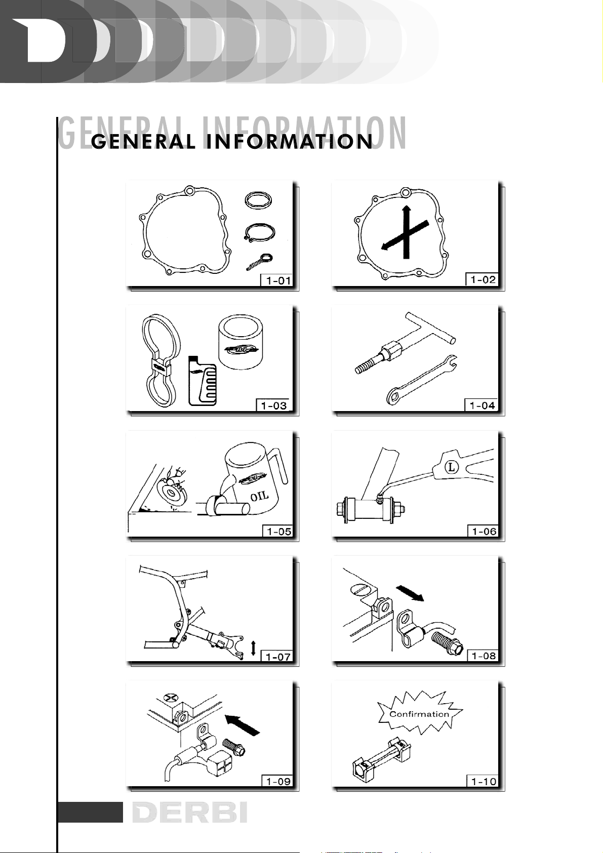
1-1. SERVICE PRECAUTIONS
01. Be sure to use the new gaskets, o-rings, ring clamps, cotter pins... during the re-assembly or any service.
(Fig. 1-01).
02. When tightening bolts, screws, or nuts, should start with large diameter boles to smaller ones. Be tighten
to the specified torque diagonally. (Fig. 1-02)
03. Only use genuine parts and lubricants as Maker’s suggestion (Fig. 1-03)
04. On servicing vehicle, be sure to use the special or common tools (Fig. 1.04)
05. After disassembly, be cleaned all the removed parts. Lubricate sliding surfaces with engine oil on engine
parts before reassembly (Fig. 1-05).
06. Apply designated greases and lubricants to the specified lubrication points. (Fig. 1-06)
07. After reassembly, check all parts for proper tightening and operation. (Fig. 1-07)
08. Disconnect battery negative (-) terminal before operation. (Fig. 1-08)
09. When connecting the battery, the positive (+) terminal should be connected first. After connection, apply
grease to battery terminals. The terminal caps shall be installed securely. (Fig. 1-09)
10. If the fuse is burned out, only replace the new fuse with the specified capacity. (Fig. 1-10)
11. When using a spanner or other tools, make sure not to damage the vehicle’s surface.
12. After service operation, check all connecting points, fasteners and lines for proper connection and
installation.
PART
1.
GENERAL
INFORMATION
10
11
1-2. BRIEFING SERVICE INFORMATION
WARNING
TO AVOID THE ENGINE RUNNING DURING REPAIR OR SERVICE, THE EXHAUST SMOKE CONTAINS POISO-
NOUS CARBON MONOXIDE GAS WHICH MAY CAUSE SERIOUS INJURY OR DEATH.
SOLUTION
1. Never run the engine in a close area.
2. If need to run the engine, be sure the working area is well ventilated and do not allow any flames or spark
in working area.
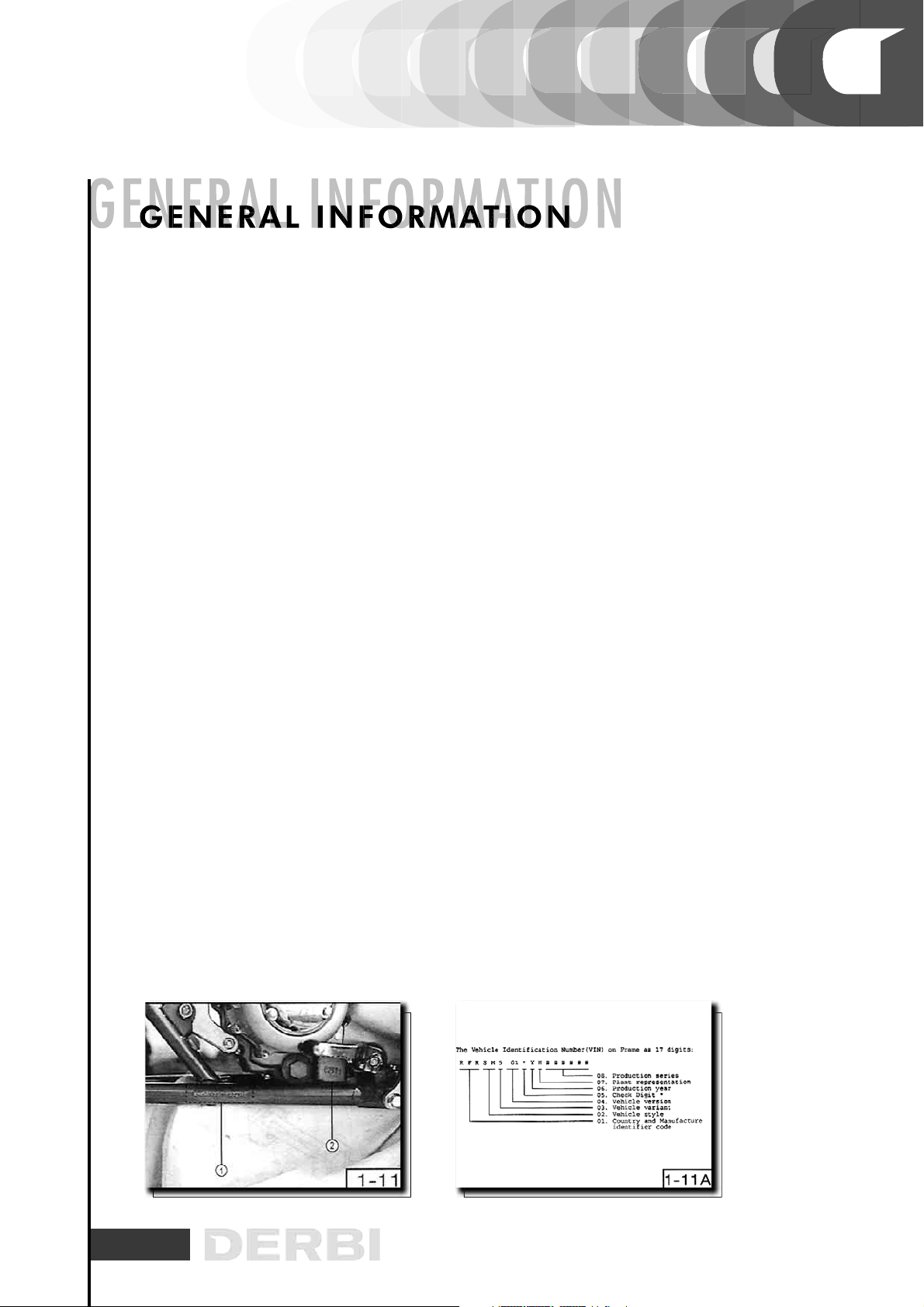
1-2-1. Identification numbers(Fig. 1-11, I-IIA)
01. The vehicle identification number (VIM) marks on the frame.
02. Engine number is marked on the engine.
1-2-2. Engine : details refer to Pare 4
01. Cylinder compression: 13 Kg./cm2
02. Idle speed: 1.500 +/- 100 rpm
03. Valve clearance: IN =0,05 mm EX = 0,05 mm
04. Ignition timing: 15 degree/I,500 rpm
05. Engine oil (4-stroke): disassembly = 1.1L change = l.0 L
1-2-3. Chassis/Frame: details refer to Part 5
01. Front brake lever free play: 10-20mm
02- Rear brake pedal free play : 10-20mm
03. Brake fluid: DOT 3 or DOT 4
1-2-4. Tire pressure --- details refer to Part 3
01. Front tire: 30 kPa (0.30kgf/cm 2;4.4psi)
02. Sear tire: 25 kPa (0 .25kgf/cm 2 ; 3 . 6psi)
1-2-5. Lubrication portion -- refer to Pare 4 & 5 details

12
1-3. CLEANING
Clean ATV regularly to protect the surface finishes and check for the damage, wear, and oil or brake fluid
leakage will enhance ATV overall appearance and general performance.
01. Block off the end of the exhaust pipe to preven 1 water entry. Next. make sure the spark plug and fuel
caps are fastened.
02. If engine case is greasy, apply de-greaser with a paint brush. Do not apply de-greaser to the chain,
sprockets or wheel axles.
03. Use only enough pressure to rinse the dirt.
CAUTION
HIGH PRESSURE WATER OR AIR MAY DAMAGE CERTAIN PARTS SUCH AS WHEEL BEARINGS, BRAKES,
TRANSMISSION SEALS AND ELECTRICAL DEVICES.
04. Use the cool water to remove dirt. Once the majority of the dirt has been taken off, wash all surfaces with
warm water and mild, detergent-type soap.
05. Rinse the ATV off immediately with clean water and dry all surfaces with a chamois, clean towel or soft
absorbent cloth.
06. Dry the chain and lubricate it to prevent rust.
07. Clean the seat with a vinyl upholstery cleaner to keep the cover pliable and glossy.
08. Automotive wax can be used on all painted and chrome plated surfaces. Avoid combination cleaner-
waxes.
09. When finishing, start the engine and let it run for several minutes. Finally, test the brakes.
WARNING
POTENTIAL HAZARD: OPERATION WITH WET BRAKES AFTER WASHING.
AWARENESS
WET BRAKES MAY HAVE REDUCED STOPPING ABILITY, INCREASING THE CHANCE OF AN ACCIDENT.
SOLUTION
TEST THE BRAKES AFTER WASHING. APPLY THE BRAKES SEVERAL TIMES AT SLOW SPEEDS TO LET FRICTION
DRY OUT THE LININGS.

13
1-4. STORAGE
Before long term storage (says 60 days or more), be sure to check the ATV for needed repairs and have it
corrected.
01. Change engine oil and oil filter.
02. Drain the fuel from tank and carburettor.
03. Clean the spark plug and put about 20-25cc engine oil (SAE 10W30 or 20W40) into the cylinder. Start
engine for a few seconds.
04. Spray anti-rusty (rust-inhibiting) oil into the inside of fuel tank.
05. Clean the drive chain thoroughly and lubricate it.
06. Lubricate all control cables.
07. Remove the battery. Be sure to re-charge battery before storage. Do not put the battery on hot or cold
place.
08. Check the tire pressure and block up the frame to raise all wheels off the ground.
09. Wash and dry the ATV and wax all painting surfaces.
10. Cover a plastic bag over the exhaust pipe.
11. Do not apply oil to any rubber parts or the seat cover.
NOTE
MAKE ANY NECESSARY REPAIRS BEFORE STORING THE ATV.

14
PART 2. SPECIFICATION
2-1. GENERAL SPECIFICATION
Dimension L/W/H: 1.610 / 1.35 / 1.010 mm or 634/40. 7/39. 7in
Seat height 770 mm or 30.3in
Wheel base 1.080 mm or 42.5in
Min. ground clearance 120 mm
Min. turning radius 3.000 mm
Weight (125/50) 152 Kg. / 154 Kg.
Engine 4 Stroke Air-Cooled
Cylinder Single - Forward Inclined
Bore * Stroke 125 cc: 56,5 x 49,5 mm; 150 cc: 62 x 49,5 mm
Displacement: 124,5 cm3; 149,5 cm3
Carburettor DTG-017 o PD-19D KEIHIN
Spark DR-8EA NGK
Starting Electric
Ignition C.D.I.
Generator ACG Fly Wheel Magneto
Battery YUASA YTX 7A-BS
Engine Oil 4 Stroke (qualified synthetic oil)
Engine Oil capacity 1,10 l.
Air- Filter Wet type element
Transmission National 5 speeds
Primary reduction Helical gear
Primary red. Ratio 4,055 (73/18T)
Secondary reduction drive chain
Secondary red. Ratio 3,333 (40/12T)
Operation Left foot operation
Gear ratio
1st: 2,769 (36/13T)
2nd: 1,882 (32/17T)
3rd: 1,272 (28/20T) or 1,4 (28/20T)
4th: 1,130 (26/23T)
5th: 0,960 (24/25T)
PART
2.
SPECIFICATION

15
Clutch type Wet, multi-blade
Operation Left hand operation
Fuel type Unleaded gasoline
Fuel tank capacity 8,0 L (1,76 lmp gal; 2,12 US gal)
Reserve fuel 2,0 L (0,44 lmp gal; 0,53 US gal)
Chassis type Steel tube frame
Caster angle 9.0 degree
Trail 40mm (1.57 in)
Suspension (F/R) double A wishbone/swing arm
Shock absorber coil spring, oil damper
Brake system (F/R) double drum/single disc
Front drum brake Right hand operation
Rear disc brake Right, foot operation
Rim steel
Front 10 x 5,5 AT
Rear 8 x 8,0 AT
Wheel travel (F/R) 180mm (7.09in)/180mm (7.09in)
Headlight type bulb type
Front 12V 18W/18W x 2
Rear 12V 21W x 1
Indicator (neutral) 12V 3,4W x 1
Fuse 15A, 250V
NOTE
THE ATV Z-S DESIGNED FOR OFF-ROAD USE MAINLY. TO MATCH DIFFERENT AREA REGULATION, ATV
MAY CHANGE OR INSTALL EXTRA DEVICE TO MATCH AREA SPECIAL REQUIREMENT SUCH AS “WORKING
MACHINE” OR “ON ROAD”.
FOR ANY QUESTIONS REGARDING THE DIFFERENT SPECIFICATION, PLEASE CONTACT THE AREA
IMPORTER.

16
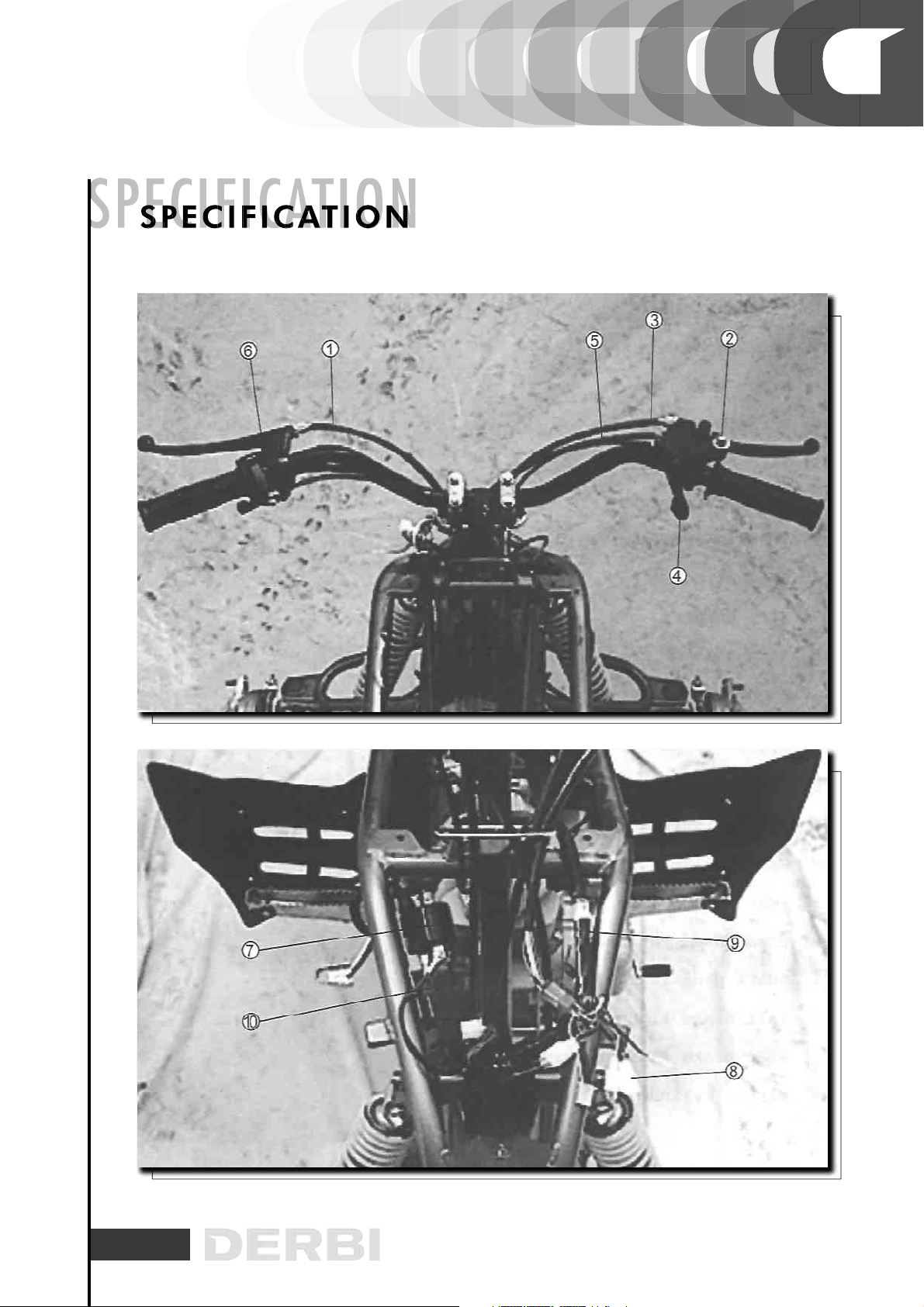
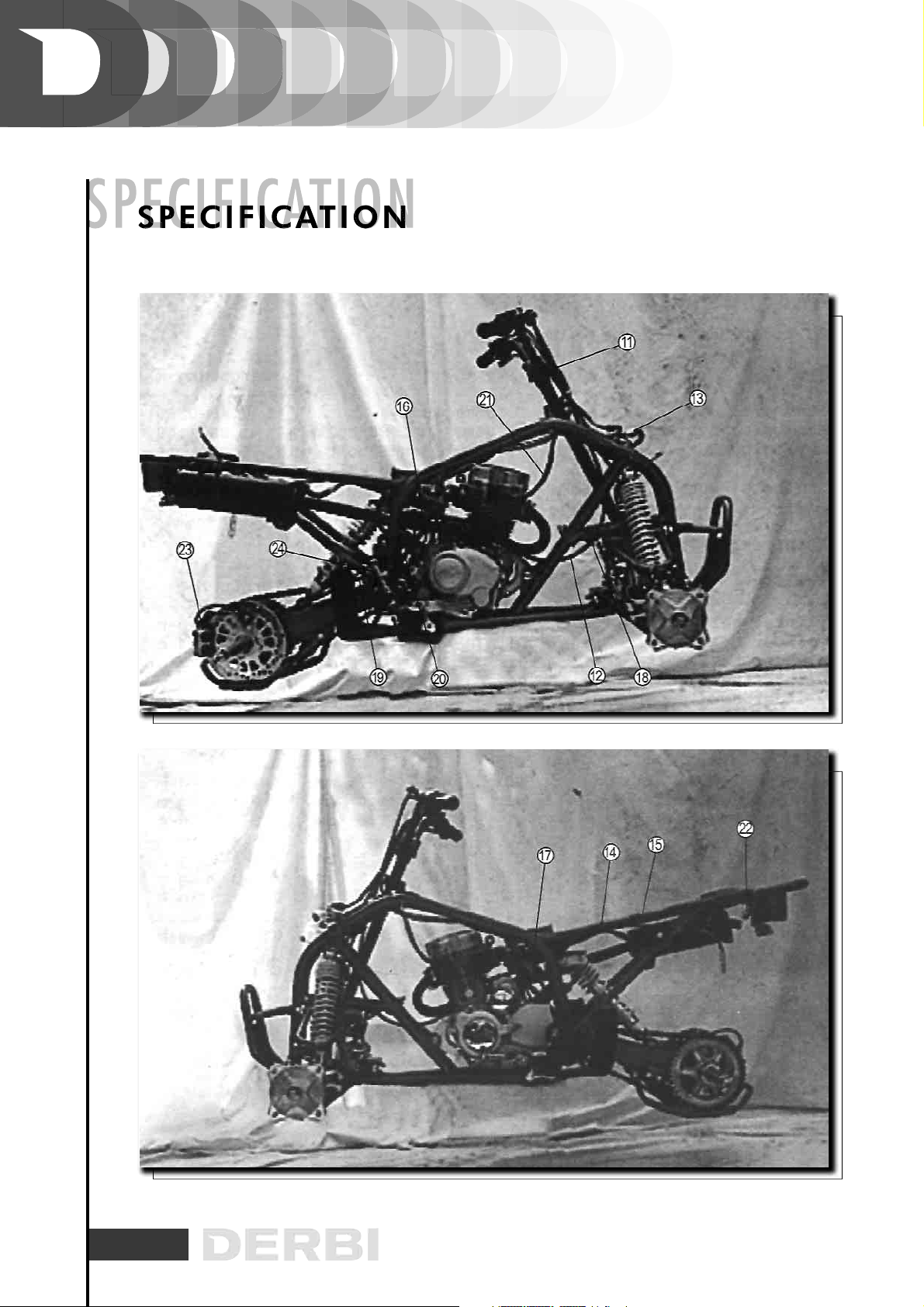
2-2. LOCATION & CABLE ROUTING
01. Clutch cable
02. Parking brake cable
03. Front brake cable
04. Throttle switch lead
05. Throttle cable
06. Handlebar switch
07. Voltage regulator lead
08. Main switch
09. Wire harness
10. Ground lead
11. Front brake cable
12. Clutch cable
13. Main switch lead
14. Wire holder
15. Clamp
16. Carburettor overflow hose
19. Flywheel magneto lead
18. Cable guide
19. Rear brake cable
20. Crankcase ventilation hose
21. Spark plug lead
22. Tail/brake light lead
23. Rear brake fluid reservoir
24. Master cylinder
17
18

19
2-3. TORQUE VALUE
2-3-1. Standard Torque Value
2-3-2. Engine Pares Torque Value
Cylinder head oil-check bolt 01 06 * 1,0 mm 0,8-1,2 Kg.-m
Oil filter lock nut 01 16 * 1,0 mm 4,0-5,0 Kg.-m
Oil Rotor cap nut 03 05 * 0,8 mm 0,4-0,8 Kg.-m
Oil pump bolt 02 06 * 1,0 mm 0,7-1,1 Kg.-m
Carburettor lock bolt 02 06 * 1,0 mm 0,8-1,2 Kg.-m
Exhaust pipe joint lock nut 02 06 * 1,0 mm 0,8-1,2 Kg.-m
Rock arm lock bolt 03 08 * 1,25 mm 1,5-2,0 Kg.-m
Valve adjusting lock nut 02 06 * 0,75 mm 1,4-1,8 Kg.-m
Bearing push bolt 01 06 * 1,0 mm 0,8-1,2 Kg.-m
SPG stopper bolt 01 06 * 1,0 mm 0,8-1,2 Kg.-m
Oil filter screen cap 01 36 * 1,5 mm 1,5-3,0 Kg.-m
Oil bolt 01 12 * 1,5 mm 2,0-3,0 Kg.-m
Crankcase assembly bolt 10 06 * 1,0 mm 0,8-1,5 Kg.-m
L crankcase cover bolt 14 06 * 1,0 mm 0,8-1,2 Kg.-m
R crankcase cover bolt 11 06 * 1,0 mm 0,8-1,2 Kg.-m
ACG bolt 03 05 * 0,8 mm 0,4-0,7 Kg.-m
ACG coil lock bolt 02 05 * 0,8 mm 0,4-0,7 Kg.-m
Perno del generador A.C. 01 10 * 1,25 mm 4,0-5,0 Kg.-m
0,45 - 0,60
0,80 - 1,20
1,80 - 2,00
3,00 - 4,00
5,00 - 6,00
05mm screw
06-nim nut, SH bolt
06mm flange bolt. nut
08mm flange bolt. nut
10mm flange bolt. nut
0,45 - 0,60
1,00 - 1,40
0,70 - 1,10
2,00 - 3,00
3,50 - 4,50
05mm bolt, nut
06mm bolt, nut
08mm bolt, nut
10mm bolt, nut
12mm bolt, nut
TORQUE (KG.-M)
TYPE TORQUE (KG.-M)
TYPE
Q’TY
ITEM TORQUE
THREAD DIA.
02
04
01
04
03
0,8-1,2 Kg.-m
2,8-3,2 Kg.-m
1,8-2,3 Kg.-m
2,3-2,8 Kg.-m
0,8-1,2 Kg.-m
Cylinder bolt
Cylinder head bolt
Cylinder head bolt
Cylinder head nut
Cylinder head cover bolt
06 * 1,0 mm
08 * 1,25 mm
08 * 1,25 mm
08 * 1,25 mm
06 * 1,0 mm
Table of contents
Other Derbi Offroad Vehicle manuals


