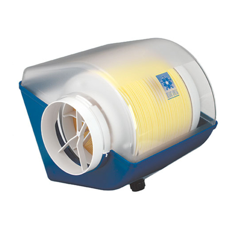
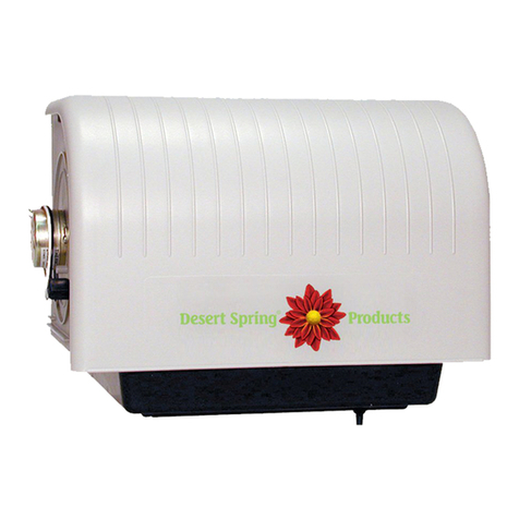
Desert Spring DS 2001 User guide

DS 2001 REVISED
Humidifier Assembly
and
Instruction Manual
Warning
• Disconnect electrical power to the furnace before starting electrical installation. Electrical
shock could result in serious injury.
• Follow furnace manufacturer's recommendations for wiring of motor power supply.
• Sharp edges may cause serious injury. Use care when making openings in ducts.
• Follow local standards and codes.
C a ut ion
• Do not install the humidifier on the furnace jacket, only on the return air duct or plenum.
• If the heating system also has central cooling, the humidifier supply takeoff must have a
damper. The damper should be closed during the cooling season.
• Do not lubricate any part of your humidifier. It is made from self-lubricating plastics.
• Do not connect the transformer to multi-speed furnace blower motors or blower motors
other than 110 VAC.
• Turn off the water supply before starting water connection and release pressure in the
system by opening a tap or flushing a toilet.
• Install the water supply valve on household water supply pressure only.
• Follow furnace manufacturer recommendations for electrical connections if provided.
• You may want to install this humidifier yourself. If you do, understand that the incorrect use
of any tool can cause injury to person or product. Be sure you understand how to use the
required tools to avoid any hazards. Arrange for professional installation if required.
• To ensure that your new humidifier will provide maximum benefit, your furnace must be
operating in accordance with the manufacturer's specifications. If your furnace is operating
outside of its manufacturer's specifications, your Desert SpringTM warranty could be voided.
• Ensure that the hot air supply temperature does not exceed 82∞Celsius (180∞Fahrenheit).
• Ensure that unit is mounted level.
T ha nk Y ou
• Thank you for selecting the Desert SpringTM Humidifier. This fine product will provide you
with years of reliable, low-maintenance service.
Contents
Parts list
Selecting a location
Assembly
Hanging the Basin
Electrical connections
Water connections
Installing the Disk Wheel
Installing the Lid and
adjusting the water level
Connecting the air supply
About humidity
Startup and shutdown
5
5
5
6
6
2
3
3
3
4
4
1

2
Warranty
This humidifier is subject to a one (1) year limited warranty issued and guaranteed by the
manufacturer. This warranty is void if the unit is damaged by careless handling, improper
installation, non-standard operating conditions, or improper maintenance. This warranty
is limited to repair or replacement of the humidifier at the discretion of the manufacturer.
No other warranty is offered or implied. This warranty is not transferable. All warranty claims
must be accompanied by a receipt or record of installation.
Parts List
• Basin 1
• Lid 1
• Motor plate 1
• Air inlet 1
• Disk wheel 1
• Float 1
• Drain 1
• Cap 1
• Hanger bracket 1
• 3/16" machine screws 3
• 3/16" nuts 3
• Humidifier-to-hanger mounting screws 3
• Plastic water line 10'
• Self-piercing valve 1
• Water line expander 1
• Hot air Take-off 1
• Damper plate 1
• 6" diameter flex duct 1
• Duct clamps 2
• Hot air Take-off mounting screws 6
• Humidistat 1
• Marettes (wire nuts) 2
• Low voltage electric wire 12'
• 24 V transformer 1
• Templates 2
• Instructions 1
Tool Suggestions
• Variety of small open end wrenches
• # 1 (green) and # 2 (red) Robertson screwdrivers (square drive)
• Electric drill with 1/16" and 3/16" drill bits
• Tin snips or compass cutter
• Test meter
• Pencil or marker

2. Assembly
• Install the float into the slot in the side of the basin. Hand tighten the nut.
3
1. Selecting a location
• This humidifier is to be mounted on the COLD AIR RETURN
(preferably on the narrow side) of a forced air heating system.
If the humidifier must be mounted on a plenum/duct which is over
12" wide, the plenum/duct should be reinforced.
• Ensure that there is sufficient clearance for the humidifier, water
supply, and air supply ductwork. If clearance problems exist with
utilities, qualified tradespeople should be called.
• Air is supplied to the humidifier with a flexible duct connected to
the air take-off (with sliding damper) mounted on the HOT AIR
SUPPLY coming out of the furnace .
• Follow the instructions on the humidifier TEMPLATE to locate
and cut holes for the humidifier and take-off.
• Note that the top of the rectangular humidifier opening and the
top of the round take-off opening should be at the same height
if possible. Mount the take-off so that the damper can
be easily opened and closed.
3. Hanging the Basin
• Hang the basin from the mounting hanger on
the COLD AIR RETURN. See template for instructions to
mount the hanger.
• Use screws to fix basin to the hanger. Start the screws in
the pilot holes and drive through into the back of the bracket.
• Recommended option: Install two screws in the upper corners
of the basin for added rigidity.
• Install the drain into the bottom of the
basin and tighten retaining nut securely.
Finger tighten these parts ensuring that the
drain is centered and does not turn.
Do not over tighten.
• Next install the cap. Optionally, connect a water
hose style ball valve and a length of garden hose
which extends to a floor drain.
• The humidifier can be configured with either
a right or left air supply. This will depend
upon the layout of your furnace.*
• Snap the motor plate and inlet into the basin.
Ensure that the basin tabs on these parts fit
into the corresponding slots in the basin. To
remove the motor plate and inlet, squeeze the
lower tab with pliers and pull upwards.
washer
float
adjustment
nut
basin
wall
slot in
basin
A
i
r
I
n
l
e
t
a
n
d
M
o
t
o
r
P
l
a
t
e
a
r
e
I
n
t
e
r
c
h
a
n
g
e
a
b
l
e
*
motor
plate air inlet
basin tab
slot
drain
ball valve (optional)
cap
*interchangeable: install air inlet on the side closest
to the hot air supply take-off.
retaining nut
basin
float
drain
washer valve washer
lid tab
overflow hole
furnace
(humidifier
shown with
inlet removed
for clarity)
basin
hanger mounts
on inside
of the cold
air plenum
Float Assembly
opt.
screw
opt. screw
stem

4. Electrical connections
• Mount the humidistat according to the guidelines supplied in the humidistat box, preferably in the
living area.
• Before making electrical connections ENSURE THAT THE POWER IS OFF!
• Consult furnace manufacturers recommendations or connect the motor leads as shown below.
5. Water connections
• USE OF SOFTENED WATER IS NOT RECOMMENDED unless you also purchased an Auto Flush.
• Before starting TURN OFF THE WATER SUPPLY and relieve the pressure.
• Install the saddle valve on a copper water line as close to the humidifier as possible.
• CAUTION: ensure that the piercing pin is backed up into the valve body. If installing on
galvanized pipe, pre drill a 1/8" diameter hole that the piercing pin fits into.
• Assemble one side of the top clamp to the bottom clamp and place over the water line
ensuring that the rubber gasket is in place over the piercing pin.
• Assemble the other side of the top clamp to the bottom clamp with remaining fastener
and tighten evenly until unit is firmly attached to water pipe.
• Connect suppled plastic water line to valve and float as shown below. Use the plastic
compression fitting and insert in the valve end of plastic line; use the expander in the float end.
If using copper line, use metal compression sleeves.
• Turn the valve handle clockwise fully to pierce the water pipe. NOTE: This is the off position.
Source of 110 Volt AC
BEST
Power to Furnace Motor:
• humidifier will only operate
when furnace does
ALTERNATIVE
AC from household wiring:
• humidifier will operate
when humidity is low
but will be most effective
when the furnace is on.
110 V
AC
junction box
or knockout
on furnace
24 Volt
transformer
humidistat
motor
(24 Volt)
humidifier
4
supplied
wire
Saddle valve body
Household
water line
Float
Expander
Compression sleeve (metal)
Plastic water line
Copper water line (not supplied)
Basin
Piercing pin
Saddle valve clamp
Rubber gasket
Insert
Compression sleeve (plastic)
110 Volt

5
motor gear
v-guide
v-guide
bearing
tab tab
6. Installing the Disk Wheel
• Using the tabs as indicators, lower the disk wheel assembly
into the V-guides on the inlet and motor plates. Ensure that
the inlet end of the axle is seated in the bearing at the bottom
of the V-guide and that the gear on the other end of the
axle is engaged with the motor gear.
disk wheel
7. Installing the Lid and adjusting
the water level
• Fit the lid onto the basin.
• Turn on the water supply and check for any leaks.
• The float assembly should be adjusted so that the height of
the water is within the range indicated by the textured bands
on the inside sides of the basin. The water should just
cover the disks (look into the inlet to see the water level).
• Adjust the float as required. Do not lift installed float against
stop or damage to float seal can occur.
• Secure the float adjustment nut with a 9/16" wrench.
• As an additional convenience, you may wish to run a hose
from the overflow hole to your floor drain. The necessary
parts are available from your local plumbing supplier.
8. Connecting the air supply
• Use one of the supplied wire clamps to hold the
flex ducting to the air take-off.
• Use the remaining wire clamp to secure the
flex duct to the humidifier's inlet.
• For maximum efficiency, do not let the flex duct
sag. If you need to trim the length of the flex duct
ensure that you cut the ends square.
• If the humidifier is far enough from the take-off to
cause strain on the ducting, it may be necessary
to buy a longer flex duct at your local hardware
store.
• Ensure damper is in the open position.
damper shown in
closed position
overflow
hole*
*(punch out if required)
water
ensure tabs on inlet and motor plate
fit into slots in lid flanges
float
adjustment
slot stop

10. Startup, maintenance and shutdown
• Turn on the water supply to the humidifier (if it has not been previously done), turn on the
electrical power and adjust the humidistat so that the humidifier starts. Adjust humidistat to the
desired setting. Regularly change the setting in accordance with the outside temperature.
• At the end of the humidifying season, turn off the water, remove the disk wheel, agitate the
water in a circular motion and drain the sediment and any water from the basin. Replace the
disk wheel and lid. Turn the humidistat off. Slide the damper to the closed position.
• Under normal conditions, minimal maintenance should be required. If you live in an area where
the mineral content of the water is high (hard water), you may wish to drain the sediment as
described above and periodically clean any minor sediment deposits from the basin and
disk wheel. Use vinegar or any cleaner approved for plastic.
• After soaking in vinegar or cleaning solution, the disk wheel should be rinsed.
• Over time metal parts may discolor. This is a normal reaction and will not affect performance.
• For excessive mineral buildup, lower water level using ball valve and scoop minerals out. Hardened
minerals will break off cleanly with minimal effort.
6
9. About humidity
• Humidity requirements will vary from home to home.
• Your comfort level is the best gauge of the correct humidity. If your windows are fogged then
you have too much humidity. If there is no moisture visible in the window corners and along
the edges then you could have too little humidity.
• In some cases it may take a week or more for the humidity to build up to the proper level.
• Humidity buildup will be hampered by sloppy fitting (or open) windows and doors, exhaust
fans, open fireplace dampers, house plants, and large attics.
• Some types of carpets produce static electricity even with the correct humidity.
• Too much humidity can cause damage to your home and furnishings, and can promote the
growth of household molds and fungi.
• In order to determine the safe relative humidity for homes exposed to various low outside
temperatures, tests were conducted and recommended humidity levels are shown in the
chart below. These levels help prevent damage to your house such as water running down
walls or even building up inside of walls. As a general guide the maximum humidity level is
attained when moisture just appears in the corners of your windows.
Disclaimer
• Except as expressly stated in this manual, ATI Manufacturing Ltd. makes no representation or warranty with respect to the
humidifier and disclaims all implied warranties including any warranty of merchantability or fitness for a particular purpose.
In no event will ATI Manufacturing Inc. be liable to any customer or user of the humidifier for any indirect, incidental, or
consequential damages or loss of revenues or profits, whether the same are foreseeable or not, occasioned
by any cause whatsoever including, but not limited to, the installation or operation of the humidifier.
Outside Air Recommended
Temperature Control Setting
-30˚C/-20˚F 15 %
-25˚C/-10˚F 20 %
-20˚C/0˚F 25 %
-10˚C/10˚F 30 %
-5˚C/20˚F 35 %
>0˚C/20˚F 40 %

DESERT SPRING®HUMIDIFIER MOUNTING TEMPLATE
TO USE TEMPLATE:
-Cut out opening from paper, retain inside as instruction sheet, outside as template.
-Tape template onto RETURN duct/plenum so that it is level and draw the opening
shape onto the duct.
-Drill starter hole in a corner, cut out opening with tin snips. Use care to cut opening
accurately. CAUTION - CUT EDGES ARE VERY SHARP.
-Hold hanger bracket against duct/plenum so that the bottom of the hanger bracket is
about 1/2" from the top edge of the opening in the duct/plenum. Ensure that it is
level and mark the three mounting bolt locations. Drill three 3/16" holes in the
duct/plenum. Mount the hanger bracket on the inside of the duct/plenum using the
3/16" machine screws and nuts.
Hanger may be dropped up to 3/4" to accommodate larger preexisting holes.
HOT AIR SUPPLY TEMPLATE
-Template is the cardboard cradle used to ship the disk wheel.
-Hold Hot Air Take-off against the HOT AIR supply and trace inside the opening.
-Drill a starter hole inside the line and cut with compass cutter or tin snips.
-Hold the air take-off over the opening and mark the screw locations.
-Drill 1/16" pilot holes or drive the screws directly into the SUPPLY duct.
-Slide the damper into place before final tightening of the mounting screws.
-Rotation of the air take-off depends on your clearance. starter hole
Damper
Air Take-off
Hanger
Installed
inside
plenum/duct
Drill holes
Hold hanger level
and mark
hole locations
1/2"
Table of contents
Other Desert Spring Humidifier manuals
