manuals.online logo
Brands
  1. Home
  2. •
  3. Brands
  4. •
  5. Det-Tronics
  6. •
  7. Relay
  8. •
  9. Det-Tronics Eagle Quantum Premier EQ3720RM User manual

Det-Tronics Eagle Quantum Premier EQ3720RM User manual

description
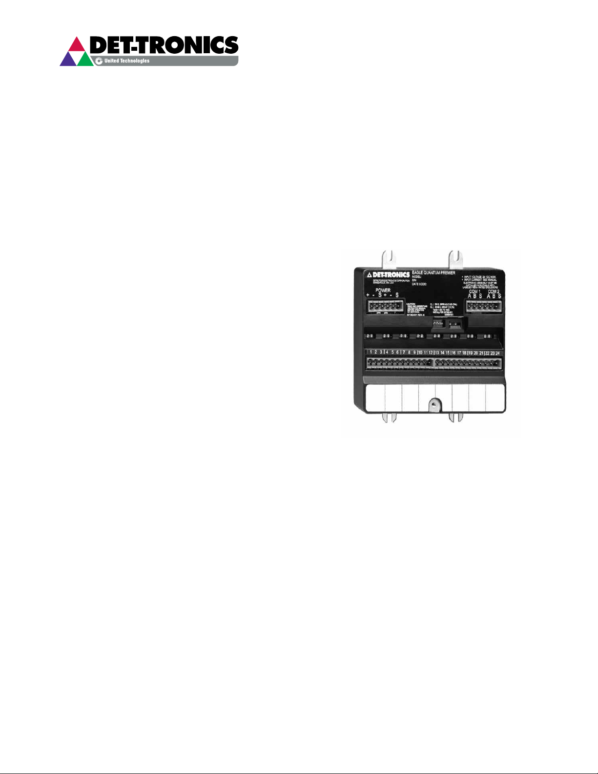
The 8 Channel Relay Module is specially designed to
expand the Output capability of the Det-Tronics Eagle
Quantum Premier®System.
The unit is designed to provide eight relay output
channels for use with non-supervised devices (PLCs,
fans, dampers, motor control centers, etc.) or devices
with their own supervision.
System status can be determined using the trouble-
shooting procedures, Eagle Quantum Safety System
Software (S3) and the status indicators on the module.
LED INDICATORS
LEDs on the front panel of the relay module are
provided for indicating device status. The LED’s are
tested upon power-up to verify their operation.
The relay module has two LEDs for the device and
two LEDs for each channel. On the device level, one
green LED indicates power, while the other amber
LED indicates a LON communication fault. For each
channel, one red LED indicates channel activation
and the other amber LED indicates that the module
operating voltage is low or that the module has not
been configured (all eight channel LEDs blink).
MOUNTING
The relay module is DIN rail or direct panel mountable
for configurations requiring installation in NEMA or
IP enclosures. DIN rail and mounting clip options
must be specified at the time of order. Refer to the
“Specifications” section for mounting arrangements and
dimensions.
FeAtUres
•ExpandstheoutputcapabilitiesoftheDet-Tronics
Eagle Quantum Premier®system
•IndividualchannelLEDsindicateActivestatus
•ProvidesremoteoutputcapabilitiesviaLON/SLC
•PanelorDINrailmounting
•PowerLEDdisplay
•Plug-inwiringconnectors
•RFIandEMIhardened(CEMarked)
•Programmablenormallyenergized/de-energized
contacts
•Programmablefailedstateonlossofcommunication
withcontroller(Failon/Failoff/Holdlaststate).
SPECIFICATION DATA
Eagle Quantum Premier®
8 Channel Relay Module
EQ3720RM
3.1 ©Detector Electronics Corporation 2014 9/14 90-1181
90-11813.1 2
speciFicAtions
POWER REQUIREMENTS—
3 watts nominal, 4 watts maximum.
INPUT VOLTAGE—
24 vdc nominal, 18 to 30 vdc. 10% overvoltage will not
cause damage to the equipment.
RELAY CONTACT RATING—
2 amperes (resistive) at 30 Vdc maximum.
0.5 ampere (resistive) at 125 Vac (FM & CSA only).
OUTPUT STYLE—
Type“C”relay(normallyopen/normallyclosed).
RESPONSE TIME—
Output actuates in <0.15 second after acknowledging
an alarm command message.
LON COMMUNICATION—
Digital communication, transformer isolated (78.5
kbps).
TEMPERATURE RANGE—
Operating: –40°F to +185°F (–40°C to +85°C).
Storage: –67°F to +185°F (–55°C to +85°C).
HUMIDITY RANGE—
5to95%RH,non-condensing.
DIMENSIONS—
Refer to Figure 1.
SHIPPING WEIGHT—
1 pound (0.45 kilograms).
CERTIFICATION—
FM/CSA: ClassI,Div.2,GroupsA,B,C,D(T4).
 ClassI,Zone2,GroupIIC(T4).
CE: ATEX/EMCDirectiveCompliant.
ATEX:
FM
APPROVED
II3G
 ExnAnCIICT4Gc.
DEMKO 03 ATEX 135246X
Tamb = –40°C to +60°C.
IECEx: IECEx ULD 10.0004X.
 ExnAnCIICT4Gc.
Tamb = –40°C to +60°C.
Special conditions for safe use:
The device shall be installed in an enclosure that
complies with all relevant requirements of EN 50021:
1999, and provides a degree of ingress protection
of at least IP54. The device may only be installed,
connected or removed when the area is known to be
non-hazardous.
For complete approval details, refer to the appropriate
Appendix in the EQP system manual (95-8533):
Appendix A - FM
AppendixB-CSA
Appendix C - ATEX & IECEx
Appendix E - CE Mark
A B C A B C A B C A B C A B C A B C A B C A B C
161 6
1 2 3 4 5 678
A B C A B C A B C A B C A B C A B C A B C A B C
161 6
1 2 3 4 5 678
4.5
(11.3)
5.02
(12.7)
2.5
(6.4)
1.35
(3.4)
5.2
(13.2)
1.66
(4.2)
5.2
(13.2) 1.9
(4.8)
4.5
(11.3)
A2449
PANEL MOUNTING DIMENSIONS DIN RAIL MOUNTING DIMENSIONS
Figure 1—Dimensions of the Relay Module in Inches (Centimeters)
FM
APPROVED
®
90-11813.1 3
instAllAtion
MOUNTING ENCLOSURE
The Relay Module must be properly installed in a
suitable enclosure that is rated for the location. The
enclosure must provide space to install and wire the
relay module and must also provide for ground wire
termination. Access into the enclosure must be gained
by using a special tool to open the enclosure. The
enclosure should be rated for the temperature range of
the location plus the temperature rise of all equipment
installed inside the enclosure. The enclosure must
be rated for electrical equipment that is going to be
installed.
NOTE
It is recommended to maintain a minimum of 4
inches clearance between the module and other
equipment to provide adequate room for wiring
and ventilation.
WIRING
All electrical connections are made to the field wiring
connectors furnished with the module. (Connectors
acceptuptoasingle12AWGwire.)Refer to Figure 2
for identification of module wiring terminals.
Connector P1, Terminals 1 to 6
24 Vdc Power Input
1 — +
2 — –
3 — Shield*
4 — +
5 — –
6 — Shield*
*Shields on power wires are optional unless required
by local codes.
Connect the module power supply to terminals 1 and
2. If additional terminals are required for powering
other devices, these devices should be connected
to terminals 4 and 5. Shields are to be connected to
terminals 3 and 6 — chassis (earth) ground terminals.
Connector P2, Terminals 1 to 6
LON Terminals
BesuretoobservepolaritywhenwiringtheLON.
1 — “A” side of signaling circuit for COM 1
2—“B”sideofsignalingcircuitforCOM1
4 — “A” side of signaling circuit for COM 2
5—“B”sideofsignalingcircuitforCOM2
3 & 6 — shield connections (shields required).
CHANNEL 8
CHANNEL 7
CHANNEL 6
CHANNEL 5
CHANNEL 4
CHANNEL 3
CHANNEL 2
CHANNEL 1
COM
6
5
4
3
2
1
COM 2 SHLD
COM 2 B
COM 2 A
COM 1 SHLD
COM 1 B
COM 1 A
SHLD
B
A
SHLD
B
A
LON FROM
PREVIOUS DEVICE
LON TO
NEXT DEVICE
POWER
6
5
4
3
2
1
SHLD
–
+
SHLD
–
+
SHLD*
–
+
SHLD*
–
+
24 VDC
INPUT VOLTAGE
24 VDC
INPUT VOLTAGE
EQ3720RM
TO
EARTH
GROUND
C2206
COMMON A
NO B
NC C
COMMON A
NO B
NC C
COMMON A
NO B
NC C
COMMON A
NO B
NC C
COMMON A
NO B
NC C
COMMON A
NO B
NC C
COMMON A
NO B
NC C
COMMON A
NO B
NC C
1
2
3
4
5
6
7
8
9
10
11
12
13
14
15
16
17
18
19
20
21
22
23
24
*SHIELDS ON POWER WIRES ARE OPTIONAL
UNLESS REQUIRED BY LOCAL CODES.
NOTE: RELAY CONTACTS SHOWN IN REST (DE-ENERGIZED) STATE.
Figure 2—Relay Module Wiring Terminal Conguration
Connectors P3 and P4
Unsupervised Output Ancillary Applications
(Unrelated to Fire Detection/Protection)
Connect external wiring to the appropriate terminals on
the relay module terminal block. See Figure 2.
CONFIGURATION
Setting Relay Module Network Address
One unique network address must be assigned to
each relay module. The address is set by the 8 switch
DIP assembly on the relay module.
When using the switches located on the relay module,
the address is binary coded and is the sum of all
switches placed in the “closed” position.
Each discrete point of a relay module has a tag number
and a descriptor for unique identification.
Det-Tronics S3Safety System Software is used
for device configuration. The following shows the
minimumsoftware/firmwarereleases:
orderinG inForMAtion
When ordering, please specify:
EQ3720RM 8 Channel Relay Module
Options Panel Mount
DIN Rail Mount
For additional information or for assistance in designing
a system to meet the needs of a specific application,
please contact:
Detector Electronics Corporation
6901 West 110th Street
Minneapolis, Minnesota 55438 USA
Operator: (952) 941-5665 or (800) 765-FIRE
Customer Service: (952) 946-6491
Fax: (952) 829-8750
Web site: www.det-tronics.com
E-mail: det-tronics@det-tronics.com
Controller Version S3 Version
2.01 2.8.0.0
90-1181
Corporate Office
6901 West 110th Street | Minneapolis, MN 55438 USA
Operator: 952.941.5665 or 800.468.3244
Customer Service: 952.946.6491 or 800.765.3473
www.det-tronics.com | Email: det-tronics@det-tronics.com
Specications subject to change without notice.
All trademarks are the property of their respective owners.
© 2014 Detector Electronics Corporation. All rights reserved.

Popular Relay manuals by other brands

Reer SR SELECT Quick installation guide

Reer

Reer SR SELECT Quick installation guide

Omron G7SA datasheet

Omron

Omron G7SA datasheet

Sensata Crydom PMP Series installation guide

Sensata

Sensata Crydom PMP Series installation guide

GE IAV53E instructions

GE

GE IAV53E instructions

Siemens SIMOCODE pro Original operating instructions

Siemens

Siemens SIMOCODE pro Original operating instructions

MICROENER IM30-B00 Operation manual

MICROENER

MICROENER IM30-B00 Operation manual

Dossena SRI3/H2 quick start guide

Dossena

Dossena SRI3/H2 quick start guide

CD Automation Revo C 2PH 1100A user manual

CD Automation

CD Automation Revo C 2PH 1100A user manual

Elko HRN- 57 manual

Elko

Elko HRN- 57 manual

Bamo ES2001 instruction manual

Bamo

Bamo ES2001 instruction manual

Moeller ZB12 Series Hardware and engineering

Moeller

Moeller ZB12 Series Hardware and engineering

White Rodgers 586 Service instructions

White Rodgers

White Rodgers 586 Service instructions

NSI 3004 Operation manual

NSI

NSI 3004 Operation manual

Broadcast Tools BOR-4 Installation and operation manual

Broadcast Tools

Broadcast Tools BOR-4 Installation and operation manual

FRER X35DL3 operating manual

FRER

FRER X35DL3 operating manual

Eaton SPDT instruction manual

Eaton

Eaton SPDT instruction manual

Westinghouse RC instructions

Westinghouse

Westinghouse RC instructions

Toshiba S2E21 instruction manual

Toshiba

Toshiba S2E21 instruction manual

manuals.online logo
manuals.online logoBrands
  • About & Mission
  • Contact us
  • Privacy Policy
  • Terms and Conditions

Copyright 2025 Manuals.Online. All Rights Reserved.