Deta 1171 Operating instructions

Combined Optical Smoke and Heat Alarm 240V with 10 Year Battery Back-Up
and RF linkable
1171
1 P a g e
User and Installation Instructions Manual
Description
Combined Optical Smoke and Heat Alarms with a 10-year sealed for life
battery back-up. The alarms mount onto a wiring base.
Multiple combined alarms can either be hardwired or wirelessly interlinked
together. Combined Optical Smoke and Heat Alarms (1171) can be
hardwired linked to other alarms within the series e.g. 1163, 1164, 1169.
The combined alarm can be wirelessly linked with a RF switch for remote
testing and silencing.
Alarms suitable for BS 5839-6 requirements for Grade D systems.
All products must be installed by a competent person in accordance BS
7671, the current edition of the IET Wiring Regulations.
Where to Locate
Combined or Smoke alarms need to be installed in circulation areas of a
dwelling, for example, hall ways and landing, as a minimum, and ideally
heat alarms need to be installed in kitchens, as required by BS 5839-6,
Code of Practice for the design, installation, commissioning and
maintenance of fire detection and fire alarm systems in domestic
premises.
Ideally, Combined or Smoke alarms should be located:
•In living and sleeping areas.
•On each floor of the dwelling.
•In every room where electrical appliances are operated, e.g. portable
heaters, tumble dryers.
•In each room where there are fossil fuel burning appliances, e.g. gas
boilers, cookers, fireplaces.
It may be necessary to install more than one Combined or Smoke alarm in
an area, e.g. in halls/corridors that are more than 9m long. See diagram 1.
Diagram 1
Positioning of Alarms
•Smoke and heat from and burning materials rise to the ceiling and
spread horizontally. Mounting the smoke alarm on the ceiling in the
centre of the room places it closest to all points in the room. Ceiling
mounting is preferred in ordinary residential dwellings.
•If smoke alarms are not positioned centrally on a ceiling within a
room, it is recommended to locate it a minimum of 300mm (12”)
from the side wall (see Diagram 2).
Diagram 2
•Put a Combined or Smoke alarm at both ends of a hallway/corridor or
large room if it is more than 9000mm (30’) long.
•In rooms with an A-shaped peaked ceiling, a sloped or cathedral
ceiling, install a Combined/smoke/heat alarm between 500mm and
1500mm from the highest point of the ceiling. (See Diagram 3).
Diagram 3
•To limit false alarms as laid within BS 5839-6, it is recommended that
smoke alarms should not be installed within 900mm (3’) of the
following: the door to a kitchen, the door to a bathroom containing a
tub or shower. If space restrictions prevent this, it must not be
located closer than 300mm (12”) from the side wall.
•Also, alarms should be positioned away from forced air supply ducts
used for heating or cooling, ceiling or whole house ventilating fans, or
other high air flow areas to limit false alarming.
•It is recommended that smoke alarms are not installed within 300mm
of light fittings.
•If positioning the alarm in the loft space, it must be easily accessible.
Ideally, from the loft hatch.
•Ideally, where possible, mount the alarm on a horizontal surface in
the loft space.
Do Not Install Combined or Smoke Alarms in the Following Places
•Alarms should not be positioned in hard-to-reach areas, such as
above stairwells, that make it difficult to gain access for maintenance
•In unventilated garages as vehicle exhaust fumes may cause false
alarm.
•In an area where the temperature may fall below 0oC or rise above
40oC, such as garages and unfinished attics.
•In dusty areas. Dust particles may cause nuisance alarm or failure to
alarm.
•In very humid areas (greater than 93% R.H.), e.g. bathrooms.
Moisture or steam can cause nuisance alarms.
•In insect-infested areas.
•Near fluorescent lights. Electronic “noise” may cause nuisance
alarms.
Important: These alarms are primarily intended for use in single
family occupancy private dwellings.
300mm Minimum
Recommended

2P a g e
Installation
This alarm should be installed as late as possible within the schedule of
works, particularly in new build properties, e.g. after decorating and
making good works.
•This alarm must not be connected to any other manufacturer alarms.
•The combined Smoke and Heat alarm is compatible with DETA item
numbers, 1163, 1165, 1164 and 1166 and 1169; and can be
hardwired interlinked with these alarms. It is not compatible with the
previous generations.
Important
The circuit powering the safety alarms must be unswitched, i.e.
permanently live. The electrical supply for mains powered alarms with
battery back-up, as required by BS 5839-6 Grade D systems, must:
i) Be an independent circuit from the consumer unit where no other
electrical equipment is connected, or
ii) A separately electrically protected, regularly used local lighting circuit
Also, where alarms are interlinked, they must be connected to a single
circuit.
Safety Instructions
•Ensure the power supply is switched off before installation and
during maintenance.
•These alarms should be installed by a competent person, e.g. a
qualified electrician.
•These alarms must be installed in accordance with the current
edition of the IET Wiring Regulations BS7671 and the Code of Practice
for the design, installation, commissioning and maintenance of fire
detection and fire alarm systems in domestic premises BS
5839-6.
•Important: Remove the alarm from the circuit for insulation
resistance testing.
If in doubt, contact a qualified electrician.
Installation
1. Release the alarm from the base by using a screw insert into the slots
and flexing outwards, see diagram. 4
Diagram 4
2. Remove the electrical connector from the alarm by squeezing the
locking arms.
3. Select the cable entry on the base and remove the cut out. Cable
entry can either be through the back of the base or via surface
mounted mini-trunking. Leave the gasket in place to prevent dust
ingress into the alarm.
4. Mount the base in the desired location using the wall plugs and screws,
as required. See Diagram 5.
Diagram 5
5. Terminate the live, neutral and earth supply cables and interlink cable
if alarms are interlinked. See Diagram 6.
Diagram 6.
L (Live): Brown conductor
N (Neutral): Blue conductor
E (Earth): Green / Yellow
I (Interlink): Grey (if using 6243Y cable)
6. Interlink
•A maximum of 12 alarms can be hardwired interlinked in a
system. If more than 12 alarms are interlinked it may result in
permanent damage.
•A maximum of 50 Combined alarms (1171 only) can be
wirelessly interlinked (see Wireless Interconnection section)
•1171 can also be installed in a hybrid system containing
hardwired and wirelessly interlinked alarms. In a hybrid system
containing hardwired and wireless interlink connections, it is
recommended that each group of hardwired alarms is
hardwired to only one wireless alarm, which interlinks
wirelessly with other wireless products.
7. For multiple alarm installations use three core and earth cable
between all the alarms to be interlinked and connect the third core of
that cable to terminal marked I. DO NOT use the earth wire for the
interlink wire. This must be treated as live, i.e. insulated and sleeved.
8. Connect the battery:
•On 1171 by pulling tab on the sealed battery cover.
•Test the alarm by pressing the TEST button.
9. Refit the electrical connector, see Diagram 7.
Diagram 7
10. Attached the alarm to the base
11. Turn on the electrical power. The green LED should be lit when the
alarm is operating from the power supply.
12. Test the alarm, including the interlink feature if more than one alarm is
installed.
Important: Remove the alarm from the circuit for insulation
resistance testing.
Wireless Interlink Instructions
Combined Optical and Heat alarm is fitted with an RF module which allows
up to 50 alarms to be wirelessly interlinked in a system. A hybrid system
can have up to 12 hardwired and 50 wirelessly interlinked alarms. For a
quick set-up of the alarm system network, it is recommended that the all
alarms are placed in close proximity to each other on a flat surface.
Setting up a wireless network
1. To setup up a wireless network, take one alarm and press the alarm
test button 3 times within 2 seconds. The RED LED on the alarm will
light up indicating that the alarm has entered the networking mode
and is ready to be paired with other alarms. The next alarm must be
added to the system within 30 seconds or the network will timeout.
2. To add another alarm to the network, press the alarm test button 3
times within 2 seconds. The secondary alarm should automatically
pair with the first; and a successful pairing is confirmed by a single
LED flash and a beep. Each time a new alarm is added, the
networking time period is extended by 30 seconds for adding more
alarms to the system.
3. Once all the alarms are added to the network, wait for 30 seconds to
allow the network to time out. To test the interlink, press and hold
the test button on any alarm in the network (see Testing the Alarm).

3P a g e
Adding alarms to an existing network
•To add another alarm to an existing wireless network, the wireless
network must be entered into networking mode. Follow steps in
section Setting up a wireless network.
Removing an alarm from an existing network
•Press the alarm test button 5 times within 2 seconds. Then press and
hold the test button immediately after the LED flashes. Alarm will
beep once to indicate that it is reset and removed from the network.
User Information
Alarm Operation
What to do when the alarm sounds
LED indicators
Green LED: Connected to mains voltage power supply.
Red LED: Flashing approximately every 40 seconds indicates
that the smoke alarm is operating properly.
RED LED-Flashing: When test button is pressed, the combination alarm
senses smoke particles or heat, the alarm goes into
alarm mode (constant pulsating sound) and the red
LED will flash once per second. The flashing LED and
pulsating sound will continue until the test button is
released, the air is cleared from alarms sensors or
the ambient temperature is normal.
RED LED-Alarm silencer (Hush mode) indication:
The red LED will flash every 8 seconds, indicating the
alarm is in the silenced (hush) mode.
Alarm silence (hush mode)
•Push TEST button to silence the alarm.
•This silence feature is only to be used when a known alarm condition,
such as smoke from cooking, activates the alarm. This feature is
useful in areas such as kitchens to prevent nuisance alarms.
•The alarm will automatically reset itself after approx. 10 minutes.
Should smoke particles or high temperature still be present, the
alarm will sound again.
Locating the initiating alarm (Nuisance alarms)
In the event of a nuisance alarm, although all interlinked alarms in the
system sound, RED LED will flash only on the initiating alarm making it easy
to identify.
CAUTION: Before using the alarm silence (hush), identify the source of the
smoke and be certain that a safe condition exists.
1. Alert small children in the home to quickly follow family escape plan.
2. Leave immediately by your escape plan. Every second counts, so
don’t waste time getting dressed or picking up valuables.
3. In leaving, don’t open any inside door without first feeling its surface.
If hot, or if you see smoke seeping through cracks, don’t open that
door! Instead, use your alternate exit. If the inside of the door is
cool, place your shoulder against it, open it slightly and be ready to
slam it shut if heat and smoke rush in.
4. Stay close to the floor if the air is smoky. Breathe shallowly through a
cloth, wet if possible.
5. Once outside, go to your selected meeting place and make sure
everyone is there.
6. Call the fire department from neighbour’s home – not from yours!
7. Don’t return to your home until the fire officials say that it is all right
to do so.
8. If there is any question as to the cause of an alarm, it should be
assumed that the alarm is due to an actual fire and the dwelling
should be evacuated immediately.
Note: These guidelines will assist you in the event of a fire, however, to
reduce the chance that fires will start, practice fire safety rules to prevent
hazardous situations.
Plan of Escape
•It is recommended that a plan of escape is developed and practiced.
A floor plan indicating doors and windows should be made and, if
possible, that two routes of escape are established.
•It is also recommended that fire extinguishers are installed and
maintained.
DANGER: If the alarm sounds, and it is not being tested, it means the unit
is sensing smoke, THE SOUND OF THE ALARM REQUIRES YOUR
IMMEDIATE ATTENTION AND ACTION.
Testing the Alarm
Important Safety Information:
Test the alarm to ensure proper operation.
1. Test alarm by pressing and holding the test button until it sounds.
The alarm will sound 3 short beeps –1.5 seconds pause, and then
repeat until the button is released.
2. If multiple alarms are installed within the dwelling, test each alarm.
Each alarm should trigger other alarms connected within 10 seconds.
Do not attempt to test the alarm with smoke or heat from a flame. Do not
ignite combustible materials and start a fire.
If no alarm sounds, the unit has a defective battery or other failure. Refer
to “Trouble Shooting” section for a solution.
Caution: Due to the loudness (85 decibels) of the alarm, always stand an
arms-length always from the unit when testing. Test the alarm
monthly to ensure proper operation. Erratic or low sound
coming from your alarm may indicate a defective alarm.
NOTE: MONTHLY TESTING IS REQUIRED
1. This alarm must not be connected to any other manufacturer alarms.
2. These alarms, item numbers, 1163,1165, 1164, 1166 and 1169 are
only compatible with each other and Combined smoke and heat
alarm 1171; they are not compatible with previous generations.
3. Test alarm monthly to ensure proper operation. The test button
accurately tests smoke and heat alarm functions. Do not use any
other test method.
4. The alarm must not be exposed to dripping or splashing water.
5. These alarms are primarily intended for use in single family
occupancy private dwellings. In multifamily buildings, each individual
living unit should have its own alarms. Do not install in non-
residential buildings. This alarm is not a substitute for a complete
alarm system.
6. The alarm may not alert every household member every time. The
alarm horn is loud in order to alert individuals to a potential danger.
However, there may be some circumstances where a household
member may not hear the alarm (e.g. excessive outdoor or indoor
noise, sound sleepers, drug or alcohol usage, the hard of hearing). If
you suspect that this alarm may not alert a household member,
install and maintain specialty alarms. Household member must hear
the alarms warning sound and quickly respond to it to reduce the risk
of damage, injury, or death that may result from fire. If a household
member is hard of hearing, install special alarms with lights or
vibrating devices to alert occupants.
7. The alarms are designed to give audible warning of a developing fire
and can only sound their alarms when they detect smoke,
combustion particles in the air or abnormal ambient temperature.
Many fires, however, are fast burning and in these circumstances the
alarm may not be triggered quick enough to ensure a safe escape.
8. The alarms have limitations. This alarm is not fool proof and is not
warranted to protect lives or property from fire. The alarms are not
a substitute for insurance. Occupants should insure their lives and
property. In addition, it is possible for the alarm to fail at any time.
For this reason, you must test the alarm monthly and replace unit
after 10 years.
Cleaning
The alarm should be cleaned on a monthly basis as a minimum. To do this:
•Turn off the electrical supply to the alarm.
•Use a vacuum cleaner with the soft brush to vacuum all sides and
covers of alarm to remove dust, dirt, and debris. Be sure all the
vents are free of debris.
•Use a damp cloth to clean the alarms cover.
•Turn the electrical supply to the alarm on.
Important: Do not attempt to remove the cover to clean inside.
This will affect the warranty.
Do not paint the alarm
Battery
1171 model has a sealed 10-year battery and must not be replaced.
4P a g e
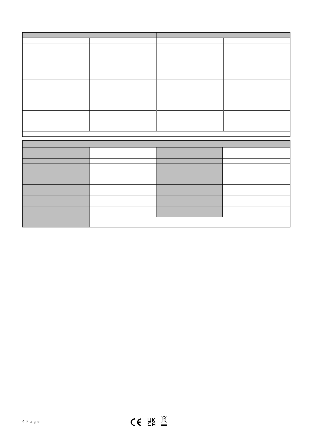
Product Specification
Voltage
220 –240V @ 50Hz with 9V battery
backup
Alarm Button –dual function
•Push to Test
•Activate Silence (hush) mode
Current
< 90mA
Silence (Hush) Time (approx.)
10 minute
Battery Specification
Lithium 9V battery DC. Brands:
CR9V, EVE
CP9V, Huiderui
Sound Pattern
ISO8201 (BI 0.5s - pause 0.5s - BI
0.5s - pause 0.5s - BI 0.5s - pause
1.5s, with the RED LED flash, then
repeat)
Battery Service Life (as backup
power)
10 year service life as backup
power
Software Version
V01
Operating Conditions
- 10 to +40°C, 25 to 95%RH
Alarm Volume
> 85dB(A) at 3 meters
Inter-linkable
Hardwired: up to 12 detectors
Wireless: up to 50 detectors
Alarm Sensitivity
Optical: 0.100 - 0.180dB/m
Heat: 54°C - 70°C
Compliance
Optical: BS EN14604:2005/AC:2008
Heat: BS 5446-2:2003
Product Disposal
These alarms come under the Waste Electrical & Electronic Equipment Regulations and must be disposed of in
accordance to these Regulations.
Trouble Shooting
Problem
Remedy
Problem
Remedy
The green LED does not light up
1. Check electrical power supply
is switched on
2. Check the electrical connector
is properly connected to the
alarm
3. If the problem still exists,
replace the alarm
Fault Mode - The alarm chirp
occurs every 16 seconds approx.
after the RED LED flashes. This
could be due to the alarm receiving
an abnormal smoke or heat signal.
1. Clean alarm. Refer to
“Cleaning ”
2. If the problem still exists,
replace the alarm
Alarm does not sound when tested.
Note: push test button for at least
five seconds while testing!
1. Ensure that the battery and
electrical connector is
properly connected
2. Clean alarm
3. If the problem still exists,
replace the alarm
The alarm sounds intermittently or
when residents are cooking, taking
showers, etc. (false alarming)
1. Press test button to pause
alarm
2. Open window or fan alarm to
3. Clean alarm
Low battery voltage mode: The
alarm chirp occurs every 40 second
approx. at the same time as the red
LED flashes once
The long life alarm battery has
reached end of life. Replace the
alarm
The RED LED light flashes three
times every 40 seconds,
accompanied by a "squeak
1. Alarm has reached the end of
its service life. Replace the
alarm as soon a possible
Warning: Do not disconnect battery to quiet an unwanted alarm. This will remove your protection. Fan the air or open window to remove smoke or dust.
S24 INS0289 V1.0 03/23 NPD 0733
Deta Electrical Company Ltd
UK: Panattoni Park Luton Road Chalton Bedfordshire LU4 9TT
EU: Unit 16 Ashbourne Ind. Est. Ashbourne Co. Meath A84 W972
deta.co.uk | Technical Helpline: +44(0)1582 544 548
8504
2531
23
23
Popular Smoke Alarm manuals by other brands

jablotron
jablotron SD-283ST quick start guide

Xtralis
Xtralis VESDA Commissioning Guide

Tyco
Tyco Visonic SMD-426 PG2 installation instructions

Texecom
Texecom Premier 412 installation manual

System Sensor
System Sensor FTX-P1 Installation and maintenance instructions

Red Smoke Alarms
Red Smoke Alarms R9 installation instructions


