Details 7 series User manual

Installation Instructions 005255D Rev D
Tools required:
Page 1 of 22
Series 7 - Adjustable Height Tables
Series 7 - Adjustable Height Tables | Installation Instructions
#2 Phillips Bit
with Extension
4mm
Hex Drive Bit
#2
Square Drive Bit

Page 2 of 22
005255D Rev D
When using an electrical furnishing, basic precautions should always be followed, including the following:
Read all instructions before using (this furnishing).
DANGER - To reduce the risk of electric shock:
1. Always unplug this furnishing from the electrical outlet before cleaning.
WARNING - To reduce the risk of burns, fire, electric shock, or injury to persons:
1. Unplug from outlet before putting on or taking off parts.
2. Close supervision is necessary when this furnishing is used by, or near children, invalids, or disabled
persons.
3. Use this table only for its intended use as described in these instructions. Do not use attachments not
recommended by the manufacturer.
4. Never operate this table if it has a damaged cord or plug, if it is not working properly, if it has been
dropped or damaged, or dropped into water.
5. Keep the cord away from heated surfaces.
6. Never drop or insert any object into any opening.
7. Do not use outdoors.
8. Do not operate where aerosol (spray) products are being used or where oxygen is being administered.
9. For loading always put heavier items at the bottom and not near the top in order to help prevent the
possibility of the furnishing tipping over.
IMPORTANT SAFETY INSTRUCTIONS
SAVE THESE INSTRUCTIONS
The power socket/outlet shall be installed near the equipment and shall be easily accessible.
www.steelcase.com/details

Overview of Assembly Process
1) Determine the table configuration.
2) Assemble 2-piece worksurface (if applicable).
3) Assemble and attach stretchers.
4) Attach legs to worksurface (with worksurface upside-down).
5) Attach control box and wire managers.
6) Connect and route cables.
7) Attach the contoller.
10) Level and clean it up.
11) PLEASE LEAVE THESE INSTRUCTIONS, AND
THE USER GUIDE, IN AN OBVIOUS PLACE
FOR THE END USER AFTER ASSEMBLY.
8) Check for binding and finish leg attachment.
9) Flip table upright and test function.
TABLE OF CONTENTS:
4
5
6 & 7
8 & 9
10 & 11
12 & 13
14 & 15
16
17 & 18
19
20
21 & 22
Lets Get Started!............................................................................................
Attaching Stretchers......................................................................................
Attaching Mounting Plate to Legs..................................................................
Mounting Legs to Worksurface......................................................................
Attaching Control Box & Wire Managers.......................................................
Connecting & Routing Cables........................................................................
Attaching the Controller.................................................................................
Finishing the Leg Installation.........................................................................
Finishing the Table Assembly.........................................................................
Guidelines on Moving the Table.....................................................................
Wiring Guide..................................................................................................
Appendix A: 2-Piece Worksurface Assembly.................................................
PAGE(S):
Page 3 of 22
005255D Rev D
www.steelcase.com/details

1
2
Prepare a large open space to assemble the table.
1
Let's Get Started!
• Sweep the floor! Screws and small parts can damage
the worksurface.
• Put down a CLEAN shipping blanket to protect the worksurface.
Unpack the worksurface and place on the shipping blanket upside-down.
2
• REMEMBER - You're looking at the UNDERSIDE of the worksurface.
Are you sure which side is left or right?
Assembling a 90ocorner table with a 2-piece worksurface?
3
Jump to Appendix 'A' now.
3
Page 4 of 22
005255D Rev D
www.steelcase.com/details

Attaching Stretchers
Page 5 of 22
005255D Rev D
www.steelcase.com/details
Layout the left and right stretcher assembly and the center
connector with the dovetails pointing down. Loosely install the
center connector to the left and right stretcher using two (2)
1/4-20 type F flat head screws with phillips #3 drive...do not
tighten. (Left and right is determined when the table is
standing on the base and is viewed from the front.)
4
Layout the left, right and center lift
columns, place the stretcher into
each dovetail, connect loosely.
5
LH ASSEMBLY
LEFT COLUMN
RIGHT COLUMN
STRETCHER
CENTER COLUMN
RH ASSEMBLY
STRETCHER
COLUMN
TOP VIEW
DOVETAIL
STRETCHER
DOVETAIL
NOTE:
On 90oor 120otables, a 21" foot is
required when the side of the
worksurface is greater than 46". If
the worksurface side is less than
46", a 18" foot is required.
Once each lift column has been
engaged, lightly tap each
connection point with a rubber
mallet 1/8-1/4 inch at a time,
until completely seated. Do not
completely install one lift
column at a time...they must be
installed incrementally.
6
NOTE:
A clean, abrasion free
surface will be necessary
for table assembly.
PHILLIPS
SCREW
DRIVE
Attaching Mounting Plate to Legs
For 2-Leg Tables:
Page 6 of 22
005255D Rev D
www.steelcase.com/details
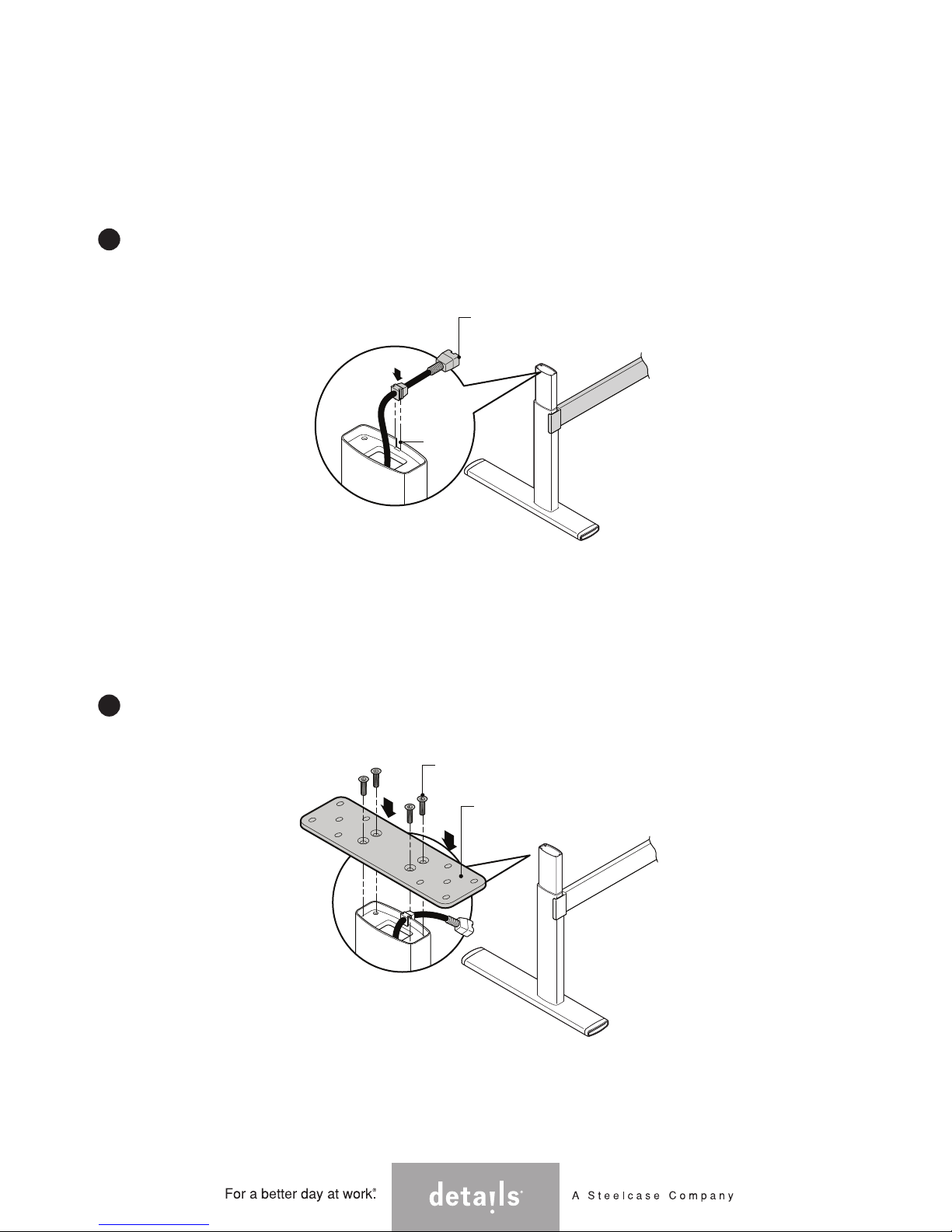
Locate and install each mounting plate using 4mm hex head
fasteners provided. Tighten securely.
8
MOUNTING PLATE
4mm HEX HEAD FASTENERS
For each lift column, fold the electrical 'pig-tail' towards
the center of the surface. Secure in the notch provided in
each lift column.
7
ELECTRICAL
PIGTAIL
NOTCH

Attaching Mounting Plate to Legs
For 3-Leg Tables:
Page 7 of 22
005255D Rev D
www.steelcase.com/details
Locate and install each mounting plate using 4mm hex head
fasteners provided. Tighten securely.
8
7
For the left and right lift columns, fold the electrical 'pig-tail'
towards the center lift column using the notch provided in
each lift column to secure. The center lift column 'pig-tail'
can be folded in either direction.
CENTER
COLUMN
ELECTRICAL
PIGTAIL
NOTE: The center lift
column ‘pig-tail’ can be
folded in either direction.
MOUNTING PLATE
CENTER
COLUMN
4mm HEX HEAD FASTENERS
(cont.)

Mounting Legs to Worksurfaces
Mounting Plate
Worksurface
Pilot Holes
= PILOT HOLE
= NO PILOT HOLE PROVIDED
For 2-Leg Tables:
With the top still upside down on the
floor, turn the base over (flipping is a 2
person job), and align the attachment
plates to the pre-drilled holes in the top.
Loosely install one fastener in each of
the pre-drilled pilot holes.
Don't install all fasteners until the unit
has been operated through one cycle
(Step 15).
9
Page 8 of 22
005255D Rev D
www.steelcase.com/details
PHILLIPS
HEAD
SCREW
Center Leg
Mounting Plate
Worksurface
Pilot Holes
TOWARD CENTER
OF WORKSURFACE

For 3-Leg Tables:
With the top still upside down on the floor, turn the base over (flipping is a 2 person
job), and align the attachment plates to the pre-drilled holes in the top.
Align the center lifting column first.
Center each pre-drilled hole in the top to the slot in the attachment plate. Loosely
install one fastener in each of the pre-drilled pilot holes.
Once the center lifting column is secured, align the left and right lifting columns in a
similar fashion by moving the plate so that all pre-drilled holes are visible.
Don't install all fasteners until the unit has been operated through one cycle (Step 15).
NOTE: Do not force the left or right lifting columns to perfectly fit the attachment
mounting holes. This can cause binding during articulation.
9
Mounting Legs to Worksurfaces (cont.)
Page 9 of 22
005255D Rev D
www.steelcase.com/details
SQUARE
SCREW
DRIVE

www.steelcase.com/details
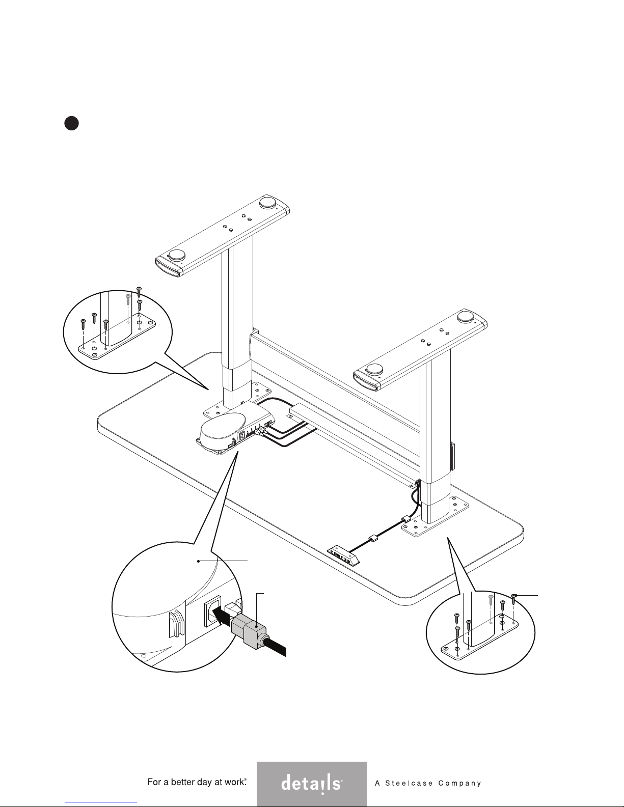
Install control box in the
predetermined location,
using pre-drilled holes.
10
Install the wire
management cableway
on the underside of the
worksurface at the rear.
11
Attaching Control Box & Wire Managers
Page 10 of 22
005255D Rev D
CONTROL BOX
2” MINIMUM
2-1/2” MAXIMUM
WIRE MANAGER
WIRE MANAGER

www.steelcase.com/details
Attaching Control Box & Wire Managers (cont.)
Page 11 of 22
005255D Rev D
Install the wire management
cableways onto the underside
of the worksurface as shown.
11
2” MINIMUM
2-1/2” MAXIMUM
WIRE MANAGER
WIRE MANAGER
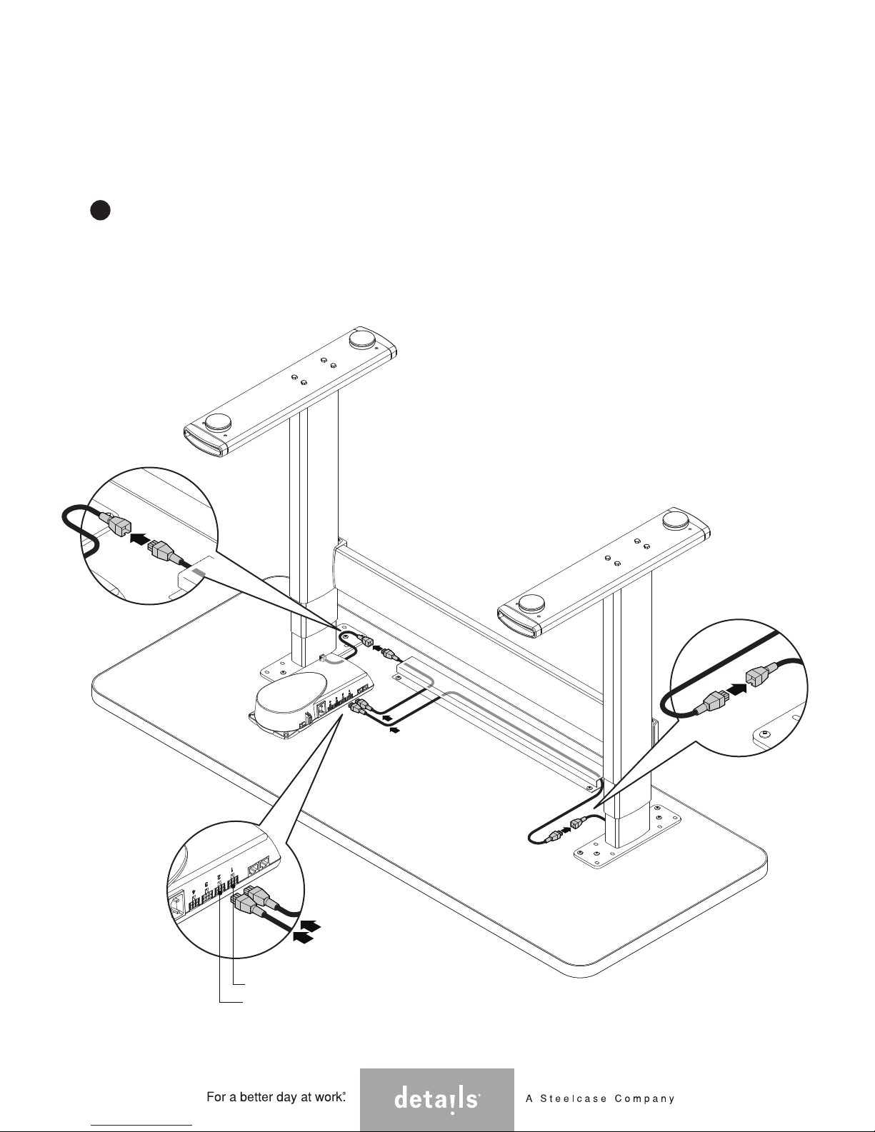
For 2-Leg Tables:
12
Connect the cables to each lifting column and connect the
terminal end to the control box. Route these cables in the
wire management cableway provided. Refer to the Wiring
Guide for more information on page 20.
For optimal wire management, connect lifting columns to the
closest port on the control box.
Connecting & Routing Cables
www.steelcase.com/details
Page 12 of 22
005255D Rev D
PORT #1
PORT #2
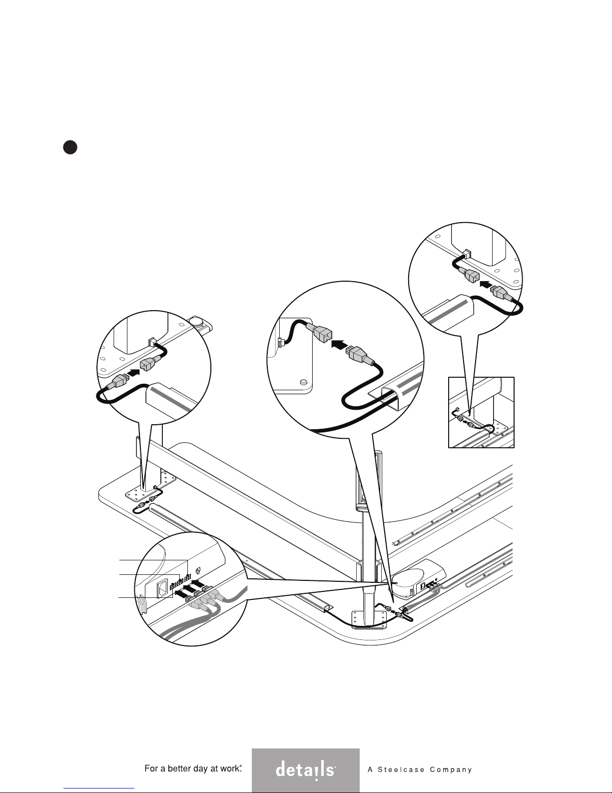
For 3-Leg Tables:
12
PORT #1
PORT #2
Connecting & Routing Cables (cont.)
www.steelcase.com/details
Page 13 of 22
005255D Rev D
Connect the cables to each of the three lifting
columns and connect the terminal end to the
control box. Route these cables in the wire
management cableway provided.
(2000mm cables to the left and right lifting
columns & 1000mm cable to the center lift
column.) Refer to the Wiring Guide on
page 20 for more information.
For best wire management, connect lifting
columns to the closest port on the control box.
PORT #3
Attaching the Controller
13
NOTE: Push button stick-on controller
installation is shown here. However, the
controller cannot be installed until the
worksurface is flipped over. Once step 18 is
performed, the controller may then be
installed.
NOTE: Remove paper backing from contoller
before installation.
Digital Desk
Panel Controller
Standard
Controller
Install the controller to the underside of the worksurface on
the side preferred by the user. (We recommend it be placed
toward the outside of the table to avoid interference in the
workspace.)
Push Button Stick-On
Controller
www.steelcase.com/details
Page 14 of 22
005255D Rev D

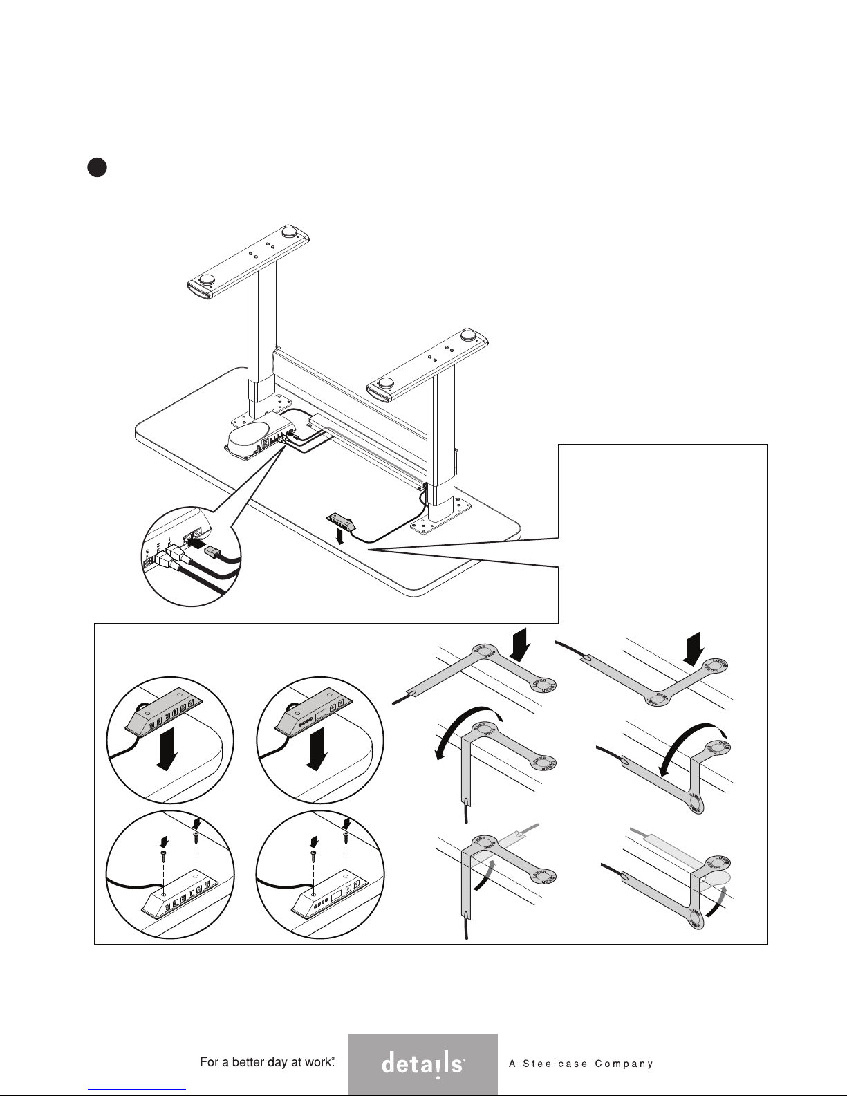
Attaching the Controller (cont.)
14
Install the wire keepers for the control wire. Peel off paper
backing and stick to worksurface. Place wire into each wire
keeper.
www.steelcase.com/details
Page 15 of 22
005255D Rev D
PAPER BACKING
WIRE KEEPER
CONTROL
WIRE
15
Plug unit in and check for binding, by running the table base all
the way through its range of motion and back again, then lower
to bottom and unplug unit. Install the remaining fasteners in
each of the remaining holes and tighten ALL screws securely.
Do not over tighten.
Finishing the Leg Installation
www.steelcase.com/details
Page 16 of 22
005255D Rev D
PHILLIPS
HEAD
SCREW
CONTROL
BOX
PLUG
16
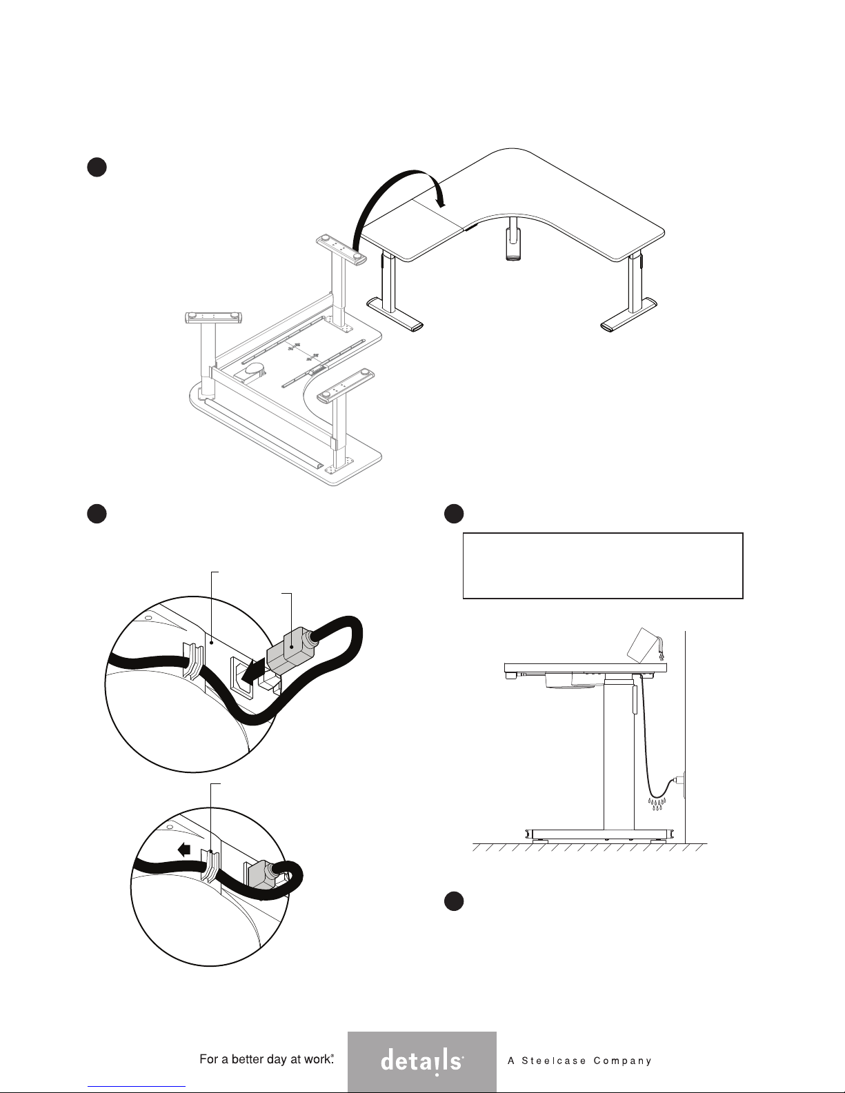
Carefully turn the table over (2 person
operation).
NOTE: Do NOT use either lifting column as a
brace when turning the table over, as this
may cause binding. The top must be lifted
free, rotated, and set down carefully.
After the table is in place, install the 120v
plug into the control box. Secure the cord
to the control box using the molded-in clip.
Plug the cord into an outlet.
CONTROL
BOX
PLUG
MOLDED CLIP
17
Route all cables through wire managers.
19
Keep all cables clear of moving parts!
CAUTION: Be sure to create a 'drip loop' in the
power cord before making the connection to a
live wall socket, to prevent electric shock if
liquids spill on power cord.
Connect power cord to power supply.
18
Finishing the Table Assembly
www.steelcase.com/details
Page 17 of 22
005255D Rev D
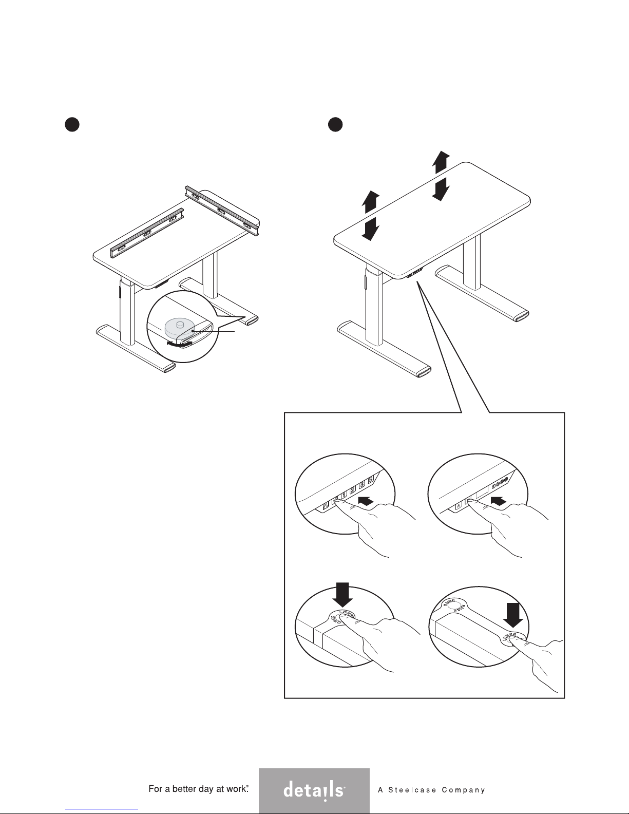
Synchronizing the Lifting Columns
Prior to initial use of the height adjustment function you must
"synchronize the system".
•Press the Down arrow until the worksurface comes to a stop at the
lowest position.
•Release the Down arrow.
•Press and hold the down arrow for approximately 5 seconds while
the table synchronizes itself. The surface will quickly lower itself
approximately 5mm, then rise approximately 5mm and finally settle
back to its lowest position.
After performing this function, the movement of all lifting columns
is synchronized by software inside the control box.
In the unlikely event that an error occurs, reset the control unit by
pressing the Up and Down buttons at the same time for 5
seconds. Then repeat the synchronizing sequence as previously
outlined above.
NOTE: Mounting of CPU and
CPU holders: Maximum height
for the 2 units cannot exceed
20-1/2".
Before use, the table must be completely leveled, front-to-back and
side-to-side using the height adjustable glides. Failure to do this
could cause the lifting columns to bind.
Before articulation, you must synchronize the lifting columns as
outlined below.
Digital Desk
Panel Controller
Standard
Controller
Push Button Stick-On
Controller
20 21
Finishing the Table Assembly (cont.)
www.steelcase.com/details
Page 18 of 22
005255D Rev D
GLIDE

Guidelines on Moving the Table
When possible, the table should be moved in a horizontal (flat) position.
If the table must be moved vertically (i.e. standing on a pallet), care must be taken to ensure no side
pressure is placed on any of the lifting columns as it is tipped into position, during transport, and when
tipped off the pallet at the new location.
Before in use in the location, the table must again be completely leveled side-to-side and front-to-back.
Failure to do so may cause binding of the lifting columns and failure to operate properly.
After moving, the lifting columns must be re-synchronized by holding 'down' arrow on the Controller
while the lifting columns seek to level themselves.
1
2
3
4
www.steelcase.com/details
Page 19 of 22
005255D Rev D
V-BRACKETS
WIRE MANAGEMENT
CABLEWAY
CONTROLLER
(can be positioned
on left or right side)
WORKSURFACE TOP
DRAW
BOLTS
LEFT
STRETCHER
LEFT LIFT
COLUMN
RIGHT
STRETCHER
RIGHT LIFT
COLUMN
CENTER LIFT
COLUMN

When connecting cables as stated in Step 12, use this guide as a reference.
Connect the cables from the Lifting Columns to the cables provided. The other end should be connected
to the Control Box. Repeat this for each leg.
Connect the end of the Controller cable into the Control Box.
Follow Steps 13 - 15 to complete the wiring installation.
Once you have completed the wiring, use the Wire Managers to hold all the cables and minimize possible
entanglements.
NOTE: Vertical wire management solutions are also available from Details. Contact your local dealer or
Steelcase.com for more information.
Wiring Guide
3
4
5
2
1
www.steelcase.com/details
Page 20 of 22
005255D Rev D
legs or stretcher in any way.
• Never attach wires to the
CONTROLLER
ATTACHMENT
PLATE
FOOT
GLIDE
LEFT LIFTING
COLUMN
RIGHT LIFTING
COLUMN
CONTROL
BOX
Table of contents
Popular Indoor Furnishing manuals by other brands

Furniture 2 Go
Furniture 2 Go 1022501 Assembly instructions

Dorel
Dorel AMERIWOOD 5675322PCOM manual

hygena
hygena 314/9195 Assembly instructions

Invacare
Invacare Solace Mattress Assembly, installation and operating instructions

Ronbow
Ronbow Signature Series Installation and care guide

rst brands
rst brands ASTER SL-OFFCE-4-A Assembly instructions

VITRA
VITRA Soft Work Assembly instructions

Lumex
Lumex FR601P Series Assembly and operating instructions

FREEWAY
FREEWAY Agile installation guide

Unfinished Furniture of Wilmington
Unfinished Furniture of Wilmington CANYON XX S-472 Assembly instructions

Garden Oasis
Garden Oasis Adirondack Chair Use and care guide

Furinno
Furinno 18053 Assembly instruction


