Detcon SmartWireless RXT-300 User manual


RXT-300 SmartWireless™
RXT-300 Wireless IM ii
Page intentionally blank
Shipping Address: 4055 Technology Forest, Suite 100, The Woodlands Texas 77381
Mailing Address: P.O. Box 8067, The Woodlands Texas 77387-8067
Phone: 888.367.4286, 281.367.4100 • Fax: 281.292.2860 • www.detcon.com • sales@detcon.com

RXT-300 SmartWireless™
RXT-300 Wireless IM iii
Table of Contents
1.0 Introduction.............................................................................................................................................. 1
1.1 Description ........................................................................................................................................... 1
1.2 RXT-300 Wireless Radio..................................................................................................................... 3
1.3 Model 100 Terminal Board (Optional)................................................................................................. 4
1.4 Smart Battery Pack (Optional) ............................................................................................................. 4
1.5 Quad Battery Charger (Optional)......................................................................................................... 5
1.6 Solar Panel (Optional).......................................................................................................................... 6
2.0 Installation................................................................................................................................................ 7
2.1 Guidelines for Safe Use........................................................................................................................ 7
2.2 Mounting.............................................................................................................................................. 8
2.2.1 Remote Mounting ......................................................................................................................... 9
2.3 Wiring Connections / Functions......................................................................................................... 12
2.3.1 VDC Power & VDC Return........................................................................................................ 12
2.3.2 Modbus™ A & B........................................................................................................................ 13
2.3.3 Alarm 1-4.................................................................................................................................... 13
2.3.4 4-20mA A & B ............................................................................................................................ 14
2.3.5 Serial Clock & Serial Data Line ................................................................................................ 15
2.3.6 Programming Data, Clock & Reset............................................................................................ 15
3.0 System Operation................................................................................................................................... 15
3.1 Station Configuration......................................................................................................................... 16
3.2 HMI Station Operation....................................................................................................................... 16
3.3 Sensor Station Operation.................................................................................................................... 16
3.4 Alarm Station Operation .................................................................................................................... 17
3.4.1 Alarm Output Properties............................................................................................................ 18
3.4.2 Alarm Zones ............................................................................................................................... 18
3.4.3 Alarm Setup Summary................................................................................................................ 19
3.5 Network Sleep.................................................................................................................................... 19
3.6 Network Control................................................................................................................................. 19
3.6.1 Alarm Reset and Alarm Silence.................................................................................................. 19
3.6.2 Alarm Inhibit .............................................................................................................................. 20
3.6.3 Alarm Test .................................................................................................................................. 20
3.6.4 RF Silence................................................................................................................................... 20
4.0 System Configuration............................................................................................................................ 21
4.1 Overview............................................................................................................................................ 21
4.2 Building a System .............................................................................................................................. 21
4.2.1 System Build Info........................................................................................................................ 21
4.2.2 Alarm Zone Build Info................................................................................................................ 22
4.2.3 RXT-300 Build Info .................................................................................................................... 23
4.2.4 Device (Sensor) Build Info ......................................................................................................... 23
4.3 System Parameters Detailed............................................................................................................... 24
4.3.1 Network Parameters................................................................................................................... 24
4.3.2 Zones .......................................................................................................................................... 25
4.4 RXT-300 Parameters Detailed ........................................................................................................... 25
4.4.1 RXT-300 Main Settings .............................................................................................................. 25
4.5 Device Parameters Detailed ............................................................................................................... 26

RXT-300 SmartWireless™
RXT-300 Wireless IM iv
5.0 Modbus Operation................................................................................................................................. 27
5.1 Modbus Addressing – Special Cases.................................................................................................. 28
5.1.1 Address Translation.................................................................................................................... 28
5.1.2 Accessing RXT-300 4-20mA Sensors.......................................................................................... 28
5.2 General Modbus™ Description.......................................................................................................... 28
5.2.1 Modbus™ Exceptions................................................................................................................. 29
5.3 Modbus™ Register Map & Description............................................................................................. 29
5.3.1 Register – Detcon Type .............................................................................................................. 30
5.3.2 Register – Alarm Outputs........................................................................................................... 30
5.3.3 Register – 4-20mA Reading........................................................................................................ 31
5.3.4 Register – Battery Info................................................................................................................ 31
5.3.5 Register – uC Firmware Version................................................................................................ 31
5.3.6 Register – Radio Firmware Version and Build.......................................................................... 31
5.3.7 Register – Radio Software Version............................................................................................. 32
5.3.8 Register – Control ...................................................................................................................... 32
5.3.9 Register – Status......................................................................................................................... 32
5.3.10 Register – Timestamp................................................................................................................. 32
6.0 Troubleshooting Guide.......................................................................................................................... 33
7.0 Warranty................................................................................................................................................ 33
8.0 Specifications.......................................................................................................................................... 34
8.1 Spare Parts.......................................................................................................................................... 35
8.2 Revision Log ...................................................................................................................................... 36
Table of Figures
Figure 1 System Example utilizing the RXT-300.............................................................................................2
Figure 2 SmartWireless™ Typical Product Family..........................................................................................2
Figure 3 Mesh Network Topology...................................................................................................................3
Figure 4 Model 100 Terminal Board.................................................................................................................4
Figure 5 Smart Battery Pack .............................................................................................................................5
Figure 6 Quad Battery Charger .........................................................................................................................5
Figure 7 Solar Panel..........................................................................................................................................6
Figure 8 RXT-300 Approval Label..................................................................................................................7
Figure 9 RXT-300 Wireless Transceiver w/Battery Assembly and Mounting Dimensions ............................8
Figure 10 RXT-300 Wireless Transceiver Remote Mounting .........................................................................9
Figure 11 Wiring Diagram for Remote RXT-300 Transceiver Mounting .......................................................10
Figure 12 Internal Alarm Output Circuit..........................................................................................................14
Figure 13 DC/Battery Alarm Board .................................................................................................................14
Figure 14 Up to two Sensors using two 4-20mA Interfaces.............................................................................15
Figure 15 Basic C1D2 Wireless Alarm Stations..............................................................................................18
Figure 16 RF Channel Comparisons between 802.15.4 and 802.11 ................................................................22
Figure 17 Modbus™ Frame Format.................................................................................................................28
Figure 18 Analog/Serial Sensor or RTU to RXT-300......................................................................................37
Figure 19 700 Serial Sensor to RXT-300.........................................................................................................37
Figure 20 Serial Sensor to RXT-300................................................................................................................38
Figure 21 HMI Panel to RXT-300....................................................................................................................38
Figure 22 Two Analog Sensors to RXT-300....................................................................................................39
Figure 23 2 Analog Sensors to RXT-300.........................................................................................................39
Figure 24 Four Serial Sensors to RXT-300......................................................................................................40
Figure 25 Four Serial Sensors to RXT-300......................................................................................................41

RXT-300 SmartWireless™
RXT-300 Wireless IM v
List of Tables
Table 1 Extension Cable Wire Identification....................................................................................................11
Table 2 RXT-300 Transceiver Wire Identification ...........................................................................................12
Table 3 Wire Gauge vs. Distance......................................................................................................................13
Table 4 Exception Codes...................................................................................................................................29
Table 5 RXT-300 Register Map........................................................................................................................30

RXT-300 SmartWireless™
RXT-300 Wireless IM vi
Page intentionally blank
Shipping Address: 4055 Technology Forest, Suite 100, The Woodlands Texas 77381
Mailing Address: P.O. Box 8067, The Woodlands Texas 77387-8067
Phone: 888.367.4286, 281.367.4100 • Fax: 281.292.2860 • www.detcon.com • sales@detcon.com

RXT-300 SmartWireless™
RXT-300 Wireless IM Rev. 2.0 Page 1 of 41
1.0 Introduction
1.1 Description
The RXT-300 SmartWireless™ Transceiver is the foundation for the Detcon family of wireless products.
Each RXT-300 comes with an internal multi-channel controller function that allows for monitoring and
generating alarms in an industrial detection system. Communication between RXT-300s occurs wirelessly
using the internal IEEE 801.15.4 radio. Detcon products using the RXT-300 have been also designed for low
power operation and can be powered using Detcon battery packs and solar panels. Since these units are both
wireless and can be set up to be battery/solar powered, they become very mobile and can be deployed without
installing a costly wiring infrastructure.
Several features have been incorporated in the RXT-300 design allowing the customer to create a robust
wireless gas detection and alarm system.
•Internal multi-channel controller – No external controller required to manage system
•Wireless Mesh Network – multiple paths of communication between RXT-300s
•Any RXT-300 can become master of the wireless network – no single point of failure
•Each RXT-300 processes local and network data and determines alarms independently
•Alarm Zones allows grouping of RXT-300s/Sensors to specific Alarm Stations
•Up to four sensors per RXT-300
•Up to two 4-20mA sensors per RXT-300
•Up to four fully configurable Alarm Outputs per RXT-300
•Can add multiple HMI (Human Machine Interface) Panels for monitoring of network
•Low power design for extended operation on battery
•Wireless Network sleep available to further reduce power consumption
•Battery Life monitoring for one SmartWireless™ Battery Pack
•Maximum 32 RXT-300s and/or 32 Sensors per Network
•Operates with a wide DC input range from 7-30VDC
•Class 1 Div 1; Groups D, C
Detection systems normally consist of a controller, sensors and alarm stations with each placed at different
locations based upon the needs of the customer. These would then be wired together to complete the system
installation and provide communication throughout the system. When using the RXT-300 SmartWireless™
Transceiver, the RXT-300 would be installed at each location and communication between devices would
occur wirelessly. Figure 1 shows an example of a possible system configuration.

RXT-300 SmartWireless™
RXT-300 Wireless IM Rev. 2.0 Page 2 of 41
Figure 1 System Example utilizing the RXT-300
The RXT-300 is usually built up as part of an assembly to satisfy one of three different applications, the HMI
(Human Machine Interface) Station for visual status of the network, the Sensor Station that has one or more
sensors attached and the Alarm Station for system alarm indication. These three basic assemblies are then
duplicated and located as needed by the customer. Figure 2 shows the Detcon versions of the typical
SmartWireless™ assemblies. Each device within the SmartWireless™ assemblies has been chosen or
designed for low power operation and can therefore be powered using the Detcon Smart Battery pack and
supplemented with a solar panel.
HMI Station Sensor Station Alarm Station
Figure 2 SmartWireless™ Typical Product Family

RXT-300 SmartWireless™
RXT-300 Wireless IM Rev. 2.0 Page 3 of 41
The RXT-300 has been designed with multiple interfaces to support these three applications. There is a single
RS-485 interface that utilizes the Modbus™ RTU protocol and can be set up as a Modbus™ Master or
Modbus™ Slave. As a Modbus™ Master the interface will support up to four Modbus™ sensors and will poll
the sensors and process alarms for those sensors. As a Modbus™ Slave it supports a single HMI (Human
Machine Interface) Panel or Modbus™ controller to display status of the sensors and RXT-300s as well as
providing control over the network such as resetting of alarms.
There are two 4-20mA inputs that can be used for monitoring 2-Wire or 3-Wire 4-20mA devices. There are
four Alarm outputs that can be configured to be Energized or De-Energized, Latching or Non-Latching and
Silence-able or Non-Silence-able. The RXT-300 can also monitor a single Detcon Smart Battery pack for
remaining battery life allowing the user to replace the battery in a timely manner.
1.2 RXT-300 Wireless Radio
The RXT-300 transceivers utilize radios based upon the IEEE 802.15.4 standard that operate at 2.4 GHz using
DSSS encoding for robustness. DSSS was initially used by the military to resist jamming but later was widely
adopted for wireless implementations since it was robust in noisy environments. DSSS transmits data across a
wider frequency range than the actual frequency range required for the information. This operation minimizes
cross talk and interference from other transceivers and is less susceptible to noise from other sources.
The IEEE 802.15.4 defines 16 separate RF Channels that can be used in the 2.4 GHz range. The default
channel is 1 but can be change if there is RF interference or if there is an existing network using that channel.
Transceivers will only respond to other transceivers with the same RF Channel.
NOTE: If there are multiple Modbus™ networks in the same vicinity each system must reside
on a different RF Channel to keep data from one appearing on the other.
The 802.15.4 standard also implements a mesh network allowing any RXT-300 transceiver to relay or repeat
data between adjacent neighbors. This makes the network very robust and provides the following immediate
benefits:
•Allows re-routing of data in case of loss of a transceiver
•Allows re-routing around wireless obstacles
•Longer distances between transceivers because data can “hop” from one transceiver to the next
•Included in sensor, controller and alarm station transceivers
•RXT-300 transceivers can be deployed with less concern about physical location
Figure 3 Mesh Network Topology
RXT-300 SmartWireless™
RXT-300 Wireless IM Rev. 2.0 Page 4 of 41
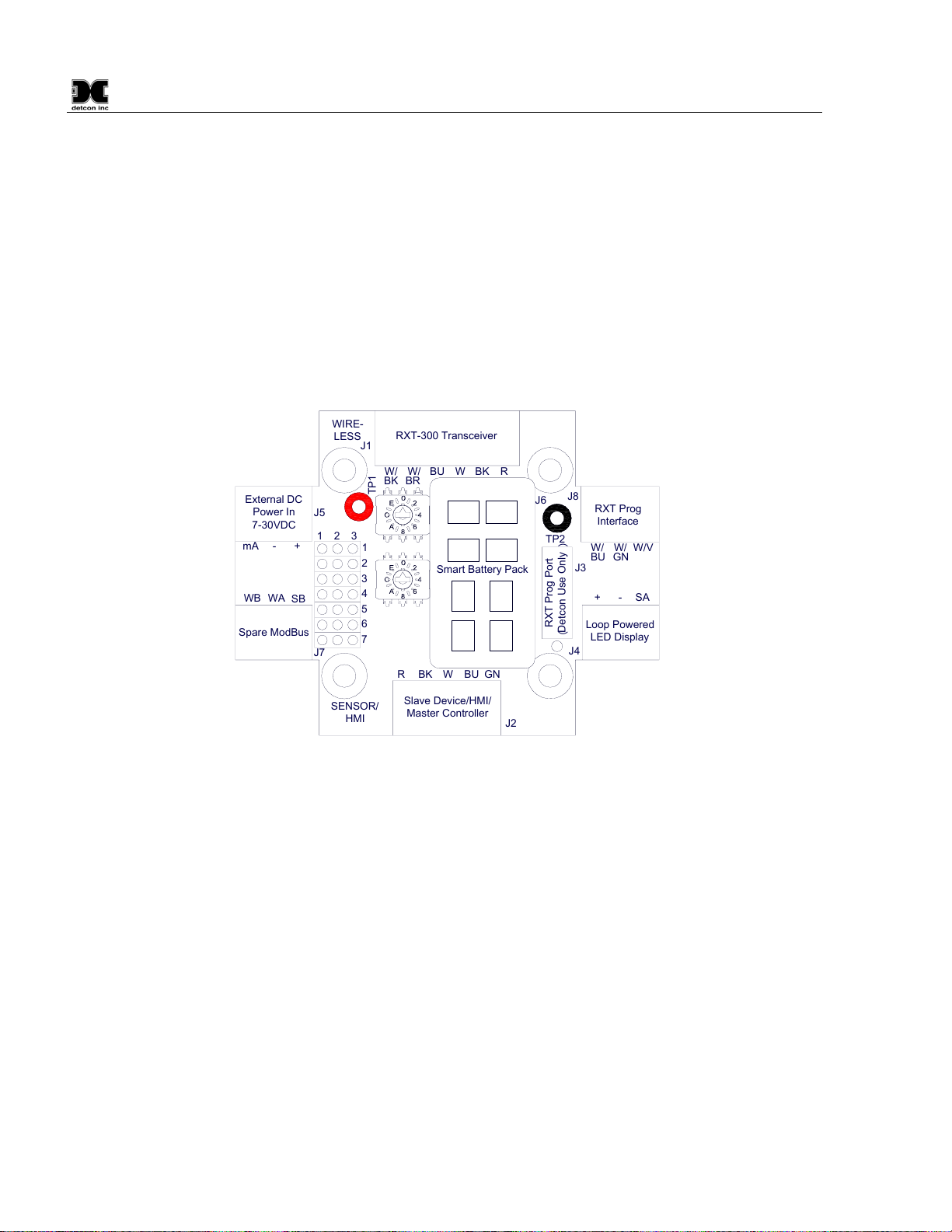
1.3 Model 100 Terminal Board (Optional)
The RXT-300 wireless transceiver can be ordered with an optional Model 100 Terminal Board mounted in a
condulet/J-Box (See Figure 4). The terminal board includes connector plugs for the following:
J1: 6-Pin Phoenix Connector RXT-300 Wireless Transceiver
J2: 5-Pin Phoenix Connector Slave Device/HMI/Master Controller
J3: 6-Pin Connector RXT-300 Programming Port (Detcon Factory use only)
J4: 3-Pin Phoenix Connector Model 100 Loop Powered LED display
J5: 3-Pin Phoenix Connector 7-30VDC External power source or 24VDC Solar Panel
J6: 8-Pin Beau Connector 12VDC Battery Power (Use only Detcon’s Smart Battery Pack)
J7: 3-Pin Phoenix Connector Spare Modbus™ Connection
J8: 3-Pin Phoenix Connector RXT Programming Interface to Wireless Transceiver
SENSOR/
HMI
RBKWBUGN
J2
BUWBKR
W/
W/BR
BK
WIRE-
LESSJ1
J4
J6
J8
J3
TP2
mA-+
+-SA
WBWASB
J7
TP1
123
234567
1
External DC
Power In
7-30VDC
Spare ModBus
RXT-300 Transceiver
Slave Device/HMI/
Master Controller
RXT Prog
Interface
Loop Powered
LED Display
RXT Prog Port
︵
Detcon Use Only
︶
J5
Smart Battery Pack
W/
BU
W/
GN
W/V
Figure 4 Model 100 Terminal Board
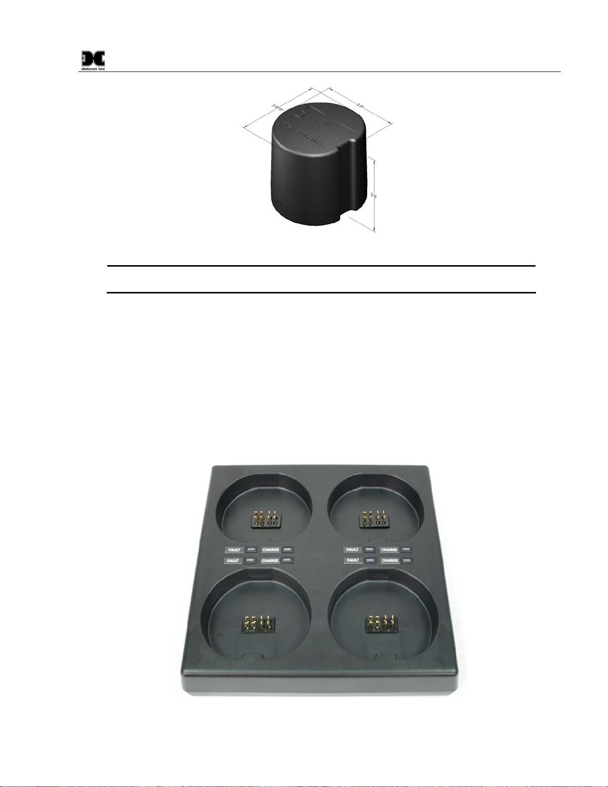
1.4 Smart Battery Pack (Optional)
The RXT-300 transceiver can also be powered by an optional battery pack that enables it to be remotely
mounted without the need for any cables because of its wireless operation. The available battery pack is
Detcon’s plug-in Smart Battery Pack which provides an output of 12VDC (See Figure 5). If installed, the
RXT-300 transceiver will detect the battery and will continuously query the battery pack for remaining battery
life. The battery pack consists of rechargeable Lithium-Ion batteries and is equipped with integrated safety
electronics that include fuel gauge, voltage, current and temperature monitoring circuits. This “smart”
circuitry continuously monitors the battery’s condition and reports critical status information to the wireless
transceiver via the Modbus™ registers. The battery pack is designed to plug onto an 8-pin Beau connector on
the Model 100 Terminal Board and should not be exposed to outside elements without being housed and
protected. Only Detcon products specifically designed to utilize these battery packs should be used.
Operating periods before recharge will vary based on devices attached along with the transceiver and the usage
of those devices, but can be as long as 2-3 months and battery life can be up to 5 years before battery pack
replacement is required. Improper use of the battery pack may be hazardous to personnel or the environment
and will void the warranty.
RXT-300 SmartWireless™
RXT-300 Wireless IM Rev. 2.0 Page 5 of 41
Figure 5 Smart Battery Pack
NOTE: The RXT-300 wireless transceiver can also be powered by a customer provided
external DC power source. Refer to section 0for more details.
1.5 Quad Battery Charger (Optional)
Detcon’s Smart Battery Pack can be charged as needed using Detcon’s optional Quad Battery Charger which
can charge up to four battery packs at one time. The Quad Battery Charger comes with a plug-in AC/DC
adapter that plugs into a standard 120VAC outlet for power. The DC end of the adapter plugs into the DC
power jack of the charger providing 24VDC. The Quad Battery Charger has four charging ports, each with 8-
pin Beau connectors for battery pack connection. The ports and connectors are keyed to prevent incorrect
positioning and connection. Each port has its own “FAULT” LED indicator and “CHARGE” LED indicator
and will display either a red light or green light depending on the status of each battery being charged.
Charging times will vary depending on the charge state of each battery pack, but a full charge of a depleted
battery pack can take up to 24 hours.
Figure 6 Quad Battery Charger
RXT-300 SmartWireless™
RXT-300 Wireless IM Rev. 2.0 Page 6 of 41
When first powered on and with no battery packs connected to the charger, all the LED indicators on the Quad
Charger should be green. When a battery pack is seated into a charging port, the “CHARGE” LED will
change from green to red indicating the battery pack is not sufficiently charged. Once fully charged, the LED
will change from red to green and the battery pack is ready to be used.
The “Fault” LED should remain green indicating that there are no problems with the battery pack or charging
port. If the “Fault” LED turns red with the battery pack connected, then there is a problem or issue with the
battery pack and it should be immediately removed and not be used. If the “Fault” LED turns red without a
battery pack connected to the charge port, then there is a problem or issue with the port and that port should no
longer be used.
Battery packs can remain connected to the charger even after a full charge indication (Green “Charge” LED) is
shown due to the protection circuitry of the battery pack which prevents any overcharging issues.
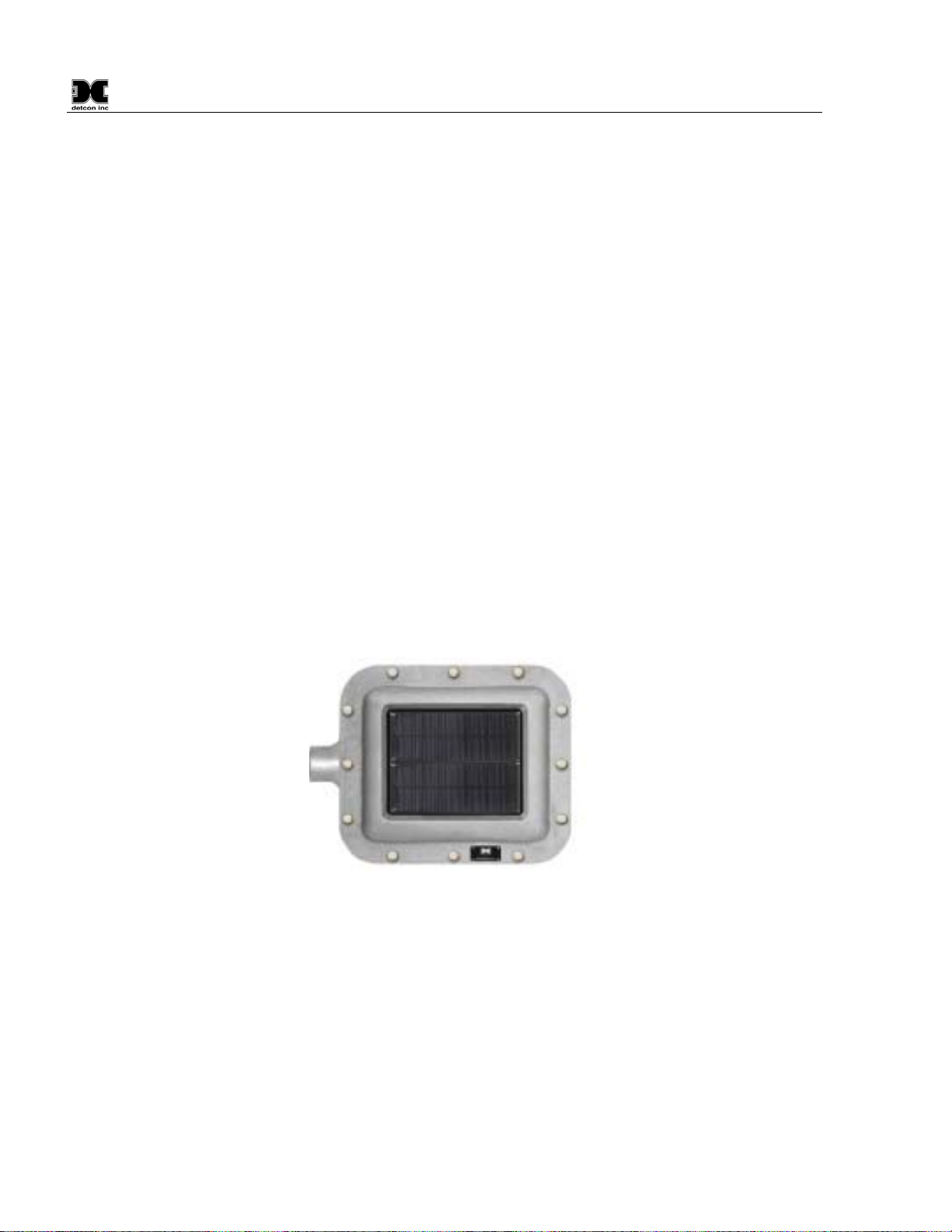
1.6 Solar Panel (Optional)
Detcon also offers an optional solar panel to be used in conjunction with the Smart Battery Pack. It provides
24VDC output and connects to the J5 connector of the Model 100 Terminal Board. This option enables
continuous operation of the wireless transceiver and charging of the battery pack eliminating the need for
external recharging. It is an ideal choice for virtually any area with sufficient daily average sunlight. Since
the solar panel is considered and external power supply, a special conduit installation will be required.
If the optional solar panel is installed, consideration should be given to position the panel where the most
sunlight is available. The solar panel can be mounted remotely to allow for maximum sunlight exposure. If
necessary, a sunshade can be used for the wireless transceiver assembly to help reduce its operating
temperature.
Figure 7 Solar Panel

RXT-300 SmartWireless™
RXT-300 Wireless IM Rev. 2.0 Page 7 of 41
2.0 Installation
2.1 Guidelines for Safe Use
1. Install unit only in areas with classifications matching with those described on the approval label. Follow
all warnings listed on the label.
Figure 8 RXT-300 Approval Label
2. Do not use in areas containing air saturation levels of Acetic Acid, Acetone, Ammonium Hydroxide, Fuel
C, Diethyl Ether, Ethyl Acetate, Ethylene Dichloride, Furfural, N-Hexane, MEK, Methanol, 2-
Nitropropane, or Toluene.
3. Ensure that the transceiver is properly threaded into a suitable explosion-proof rated junction box with a
female ¾” NPT threaded connection. The sensor should be threaded up at least 5 full turns until tight.
Avoid use of Teflon Tape, or any type of non-conductive pipe thread coating on the NPT threaded
connection.
4. A good ground connection should be verified between the sensor’s metal enclosure and the junction box.
If a good ground connection is not made, the sensor can be grounded to the junction box using the sensor’s
external ground lug. Also verify a good ground connection between the junction box and earth ground.
5. Proper precautions should be taken during installation and maintenance to avoid the build-up of static
charge on the plastic weather-guard of the transceiver.
6. Do not substitute components that are not authorized by the scope of the safety approval. This may impair
the intrinsic safety rating.
7. Do not operate the unit outside of the stated operating temperature limits.
8. Do not operate the unit outside the stated operating limits for voltage supply.
9. The sensor power supply common (black wire) must be referenced to the metal enclosure body (ground)
during installation.
10. These units are designed to meet EN60079-0, EN60079-1, EN60079-11, UL913 7th Ed., and CSA C22.2
No.157-92.
11. These units are designed have a maximum safe location voltage of Um=30V.
12. These units pass dielectric strength of 500VRMS between circuit and enclosure for a minimum of 1
minute at a maximum test current of 5mA.

RXT-300 SmartWireless™
RXT-300 Wireless IM Rev. 2.0 Page 8 of 41
2.2 Mounting
The RXT-300 wireless transceiver should be vertically oriented and mounted to an explosion-proof enclosure
or junction box. The J-Box contains the optional Model 100 Terminal Board. If a battery pack is used,
Detcon’s custom J-Box is needed to accommodate both the terminal board and the battery pack plus a T-Outlet
box with a drain is required (See Figure 9). The RXT-300 wireless transceiver assembly is typically mounted
on a wall or pole.
Obstacles between RXT transceivers can impact RF line-of-sight and may result in communication problems.
Each transceiver should be in view of at least one other transceiver. In some cases, it may be necessary to
extend and elevate the RXT transceiver away from the J-Box/device assembly. Refer to section 2.2.1 for such
remote mounting applications
Detcon offers an optional mounting plate that can be used for mounting the wireless transceiver assembly on a
wall or pole. If ordered with this option, secure the wireless transceiver assembly to the mounting plate using
two of the four 3/8” diameter holes located on the top face of the mounting plate (If not already done so from
the factory). The whole assembly can now be mounted on a secure wall using the four 7/16” diameter holes
located on the base of the mounting plate (See Figure 9). The assembly can also be mounted to a pole with
two U-Bolts secured through the 7/16” holes on the base.
NOTE: If wall mounting without the mounting plate, make sure to use at least 0.5” spacers
underneath the J-Box’s 1/4” mounting holes to move the wireless transceiver assembly away
from the wall and allow clearance to the transceiver.
8-32 tapped
ground point
14
" mounting
holes x2
T-Outlet Box
w/Drain
5.5"
6.1"
3.5"
2.5"
8"
7"
5"
RXT Series Wireless Transceiver
34
" NPT Ports
Wall
︵
or other
mounting surface
︶
7.135"
7
16
" mounting
holes x4
38
" mounting
holes x4
10" Typ.
Detcon Mounting Plate
︵
Optional
︶
Custom Aluminum J-Box
︵
For Battery Option
︶
15.7"
Figure 9 RXT-300 Wireless Transceiver w/Battery Assembly and Mounting Dimensions

RXT-300 SmartWireless™
RXT-300 Wireless IM Rev. 2.0 Page 9 of 41
2.2.1 Remote Mounting
The RXT-320 wireless transceiver is normally connected directly to the J-Box containing the battery/terminal
board assembly. In situations where RF line-of-sight is diminished by obstructions, it may be necessary to
remotely mount the wireless transceiver away from this J-Box. Remote separation distances of up to 15 feet
are possible with the recommended cable. Such an installation will require an additional J-Box which
connects to the separated transceiver and houses Detcon’s 8-position terminal board with Ground board plus
additional hardware (See Figure 10).
Power, Modbus & I²C
Remote RXT-300 Wireless Transceiver
Extension Cable to/from
Remote RXT Transceiver
Up to 15' Length
J-Box w/
Model 100
Terminal Board
Remote J-Box w/
8-Position
Terminal Board
3
4" NPT Cord Connectors
(Cable Glands) Required
SENSOR/
HMI
RBKWBUGN
J2
BUWBKR
W/
W/BR
BK
WIRE-
LESSJ1
J4
J6
J8
J3
TP2
mA-+
+-SA
WBWASB
J7
TP1
123
23 4567
1
External DC
Power In
7-30VDC
Spare ModBus
RXT-320 Transceiver
Slave Device/
Master Controller/
Remote Monitor
RXT Prog
Interface
Loop Powered
LED Display
RXT Prog Port
︵
Detcon Use Only
︶
J5
Smart Battery Pack
W/
BU
W/
GN
W/V
3
4" NPT T-Outlet
Box w/Drain
Remote 3
4" NPT
T-Outlet Box w/Drain
Figure 10 RXT-300 Wireless Transceiver Remote Mounting
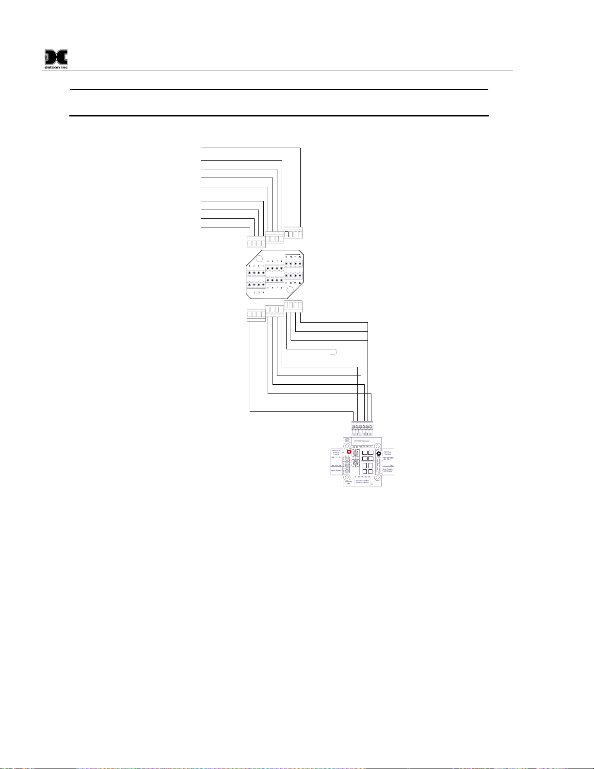
A custom extension cable needs to be built per Figure 11 to interface the remote transceiver to the Model 100
Terminal Board. The recommended cable for remote transceiver separation is Belden 1421A (24AWG
shielded twisted pair, 4 pairs w/drain wire).
NOTE: It is highly recommended to install the extension cable inside rigid metal conduit to
eliminate potential EMI and RFI interference and to maintain a Class I Division I rating.
NOTE: Color coding of the cable will no longer match the color coding on the Model 100
Terminal Board for the J1 connector.
RXT-300 SmartWireless™
RXT-300 Wireless IM Rev. 2.0 Page 10 of 41
NOTE: Programming of RXT transceiver from the Model 100 Terminal Board will be
disabled.
Blu (Modbus A)
Wht (Modbus B)
Red (Pwr +)
Wht/Vio (Prog Reset)
Wht/Grn (Prog Data)
Wht/Blu (Prog Clock)
Wht/Blk (Serial Clock)
Wht/Brn (Serial Data)
Blk (Gnd -)
Wht/Orn (Gnd -)
Brn/Wht (Gnd -)
Drain Wire
Wht/Brn (Serial Data)
Blu/Wht (Modbus A)
Wht/Blu (Modbus B)
Orn/Wht (Pwr +)
Grn/Wht (Gnd -)
Wht/Grn (Serial Clock)
8-Position Terminal
Board with Ground
Model 100
Terminal Board
Extension Cable
(Belden 1421A)
RXT-300
Transceiver Wiring
4-Pin Phoenix
Connectors
6-Pin Phoenix
Connector
4-Pin Phoenix
Connectors
SENSOR/
HMI
RBKWBUGN
J2
BUWBKR
W/
W/BR
BK
WIRE-
LESSJ1
J4
J6
J8
J3
TP2
mA-+
+-SA
WBWASB
J7
TP1
123
234567
1
External DC
Power In
7-30VDC
Spare ModBus
RXT-300 Transceiver
Slave Device/HMI/
Master Controller
RXT Prog
Interface
Loop Powered
LED Display
RXT Prog Port
︵
Detcon Use Only
︶
J5
Smart Battery Pack
W/
BU
W/
GN
W/V
Figure 11 Wiring Diagram for Remote RXT-300 Transceiver Mounting
Remote Mounting Steps
1. Remove the J-Box cover of the RXT-300 wireless transceiver assembly.
2. If the wireless transceiver assembly has the Smart Battery Pack, unplug the battery pack from the
terminal board by pulling the battery pack out of the junction box.
3. Identify the J1 6-pin Phoenix connector and the J8 3-pin Phoenix connector on the Model 100 Terminal
Board and disconnect from the board. Remove all transceiver wire connections from the connectors.
Reconnect the 3-pin connector to its corresponding place and save the 6-pin connector for step 13.
4. Use a wrench at the bottom section of the RXT transceiver and unthread the RXT until it can be removed.
5. Feed the RXT transceiver wires through the ¾” NPT hole of the remote T-Outlet box connected to the
remote J-Box and thread the transceiver into the remote T-Outlet box until tight.
6. Remove all 6 of the 4-pin Phoenix connectors from the 8-position terminal board with Ground in the
remote J-Box and connect the RXT transceiver wires to 3 of the Phoenix connectors per the wiring

RXT-300 SmartWireless™
RXT-300 Wireless IM Rev. 2.0 Page 11 of 41
diagram in Figure 11. Reference Table 2 RXT-300 Transceiver Wire Identification for color code
identification.
NOTE: Wires that are not used should be individually capped off and secured out of the way
in the T-Outlet box so that they are not exposed to any active components, power, or ground.
7. Reconnect these 3 Phoenix connectors to their corresponding places back on the 8-position terminal
board with Ground.
8. Measure out the cable to be used for the extension cable to be no more than 15 feet long. Feed one end of
the cable through a ¾” NPT cord connector (cable gland) and then into the ¾” NPT hole located on the
bottom of the remote J-Box.
9. Connect the cable wires of the extension cable to the remaining three 4-pin Phoenix connectors from step
6per the wiring diagram in Figure 11. Reference Table 1 Extension Cable Wire Identification for
color code identification.
10. Reconnect these 3 remaining Phoenix connectors to their corresponding places back on the 8-position
terminal board with Ground and thread the ¾” NPT cord connector to the bottom of the remote J-Box.
11. Install the J-Box cover of the remote J-Box.
12. Feed the other end of the cable through another ¾” NPT cord connector and then into the ¾” NPT hole of
the T-Outlet box connected to the J-Box housing the Model 100 Terminal Board.
13. Connect the cable wires to the 6-pin Phoenix connector from step 3per the wiring diagram in Figure 11.
Reference Table 1 Extension Cable Wire Identification for color code identification.
14. Reconnect the 6-pin Phoenix connector back to J1 of the Model 100 Terminal Board and thread the ¾”
NPT cord connector to the T-Outlet box.
NOTE: Color coding of the cable will no longer match the color coding on the Model 100
Terminal Board for the J1 connector.
NOTE: Programming of RXT transceiver from the Model 100 Terminal Board will be
disabled.
15. Plug battery pack back in place and reinstall the J-Box cover from step 1.
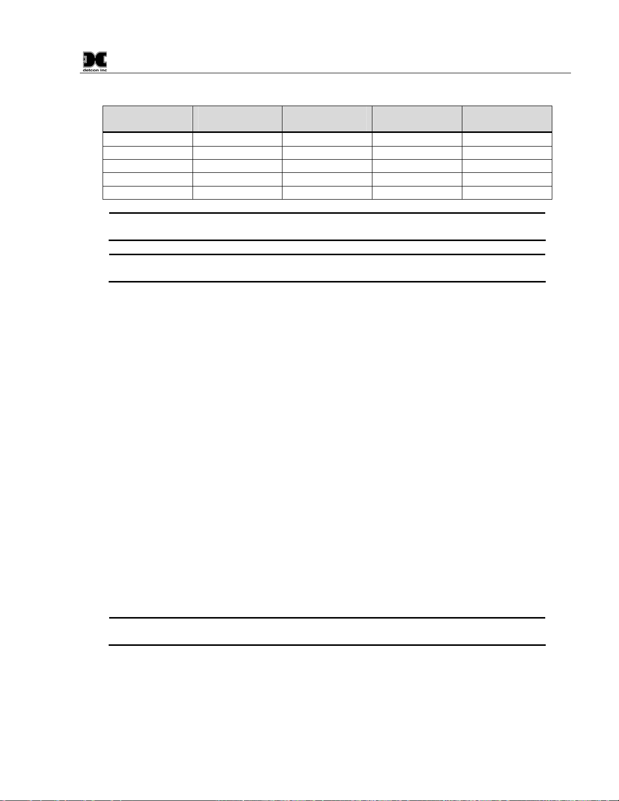
Table 1 Extension Cable Wire Identification
Function Color Reference
VDC Power (+) Orange/White
VDC Return (-) Green/White
Modbus A (+) Blue/White
Modbus B (-) White/Blue
Serial Clock (SCL) White/Green
Serial Data Line (SDA) White/Brown
Common Ground White/Orange
Common Ground Brown/White
Drain Wire Bare (No Color)

RXT-300 SmartWireless™
RXT-300 Wireless IM Rev. 2.0 Page 12 of 41
2.3 Wiring Connections / Functions
Depending on use and function, the RXT-300 wireless transceiver can be wired in different ways to different
devices. It is important to insure that the wiring is correct for the device to operate properly. Wire
identification for the transceiver can be found in Table 2 RXT-300 Transceiver Wire Identification.
Table 2 RXT-300 Transceiver Wire Identification
Function Color Reference
VDC Power (+) Red
VDC Return (-) Black
Modbus™ A (+) Blue
Modbus™ B (-) White
Alarm 0 Brown
Alarm 1 Orange
Alarm 2 Violet
Alarm 3 Gray
4-20mA A Green
4-20mA B Yellow
Serial Clock (SCL) White/Black
Serial Data Line Data (SDA) White/Brown
Programming Data White/Green
Programming Clock White/Blue
Programming Reset White/Violet
NOTE: Reference Figure 18 through Figure 25 at the end of this manual for multiple wiring
examples.
2.3.1 VDC Power & VDC Return
All RXT-300 wireless transceivers need to have DC power applied to the transceiver’s red (VDC power) and
black (VDC return) wires. The power requirements for the transceiver are such that the DC voltage input
range is 7 to 30 volts. This power will normally be supplied by the device the transceiver is connected to, but
can come from alternate DC sources such as the optional Smart Battery Pack, solar panel or external customer
supplied DC source.
If an external power source is installed, the RXT-300 wireless transceiver requires two conductor connections
for the power supply. External DC power can be customer provided with an output voltage range between 7 to
30VDC or by Detcon’s optional 24VDC solar charging panel. Both of these alternatives will provide
continuous operation of the assembly and can be installed in conjunction with the optional battery pack,
providing a constant power source. The external power supply will also maintain the battery pack fully
charged with no overcharging issues to be concerned with due to the battery pack’s “smart” circuitry. In this
configuration, external charging of the battery pack will not be necessary. In the event the external power
fails, the battery pack will continue to power the wireless transceiver assembly until external power is restored
or the battery is discharged.
If the Model 100 Terminal Board option is not used, power to the transceiver should be directly applied to its
red and black wires accordingly. If the terminal board is used, wiring designations for power are ‘+’ and ‘-’
(External DC Power In) on the J5 connector of the Model 100 Terminal Board. The maximum wire length
between the transceiver assembly and a 24VDC source is shown in Table 3 Wire Gauge vs. Distance.
RXT-300 SmartWireless™
RXT-300 Wireless IM Rev. 2.0 Page 13 of 41
Table 3 Wire Gauge vs. Distance
AWG Wire Dia. Meters Feet Over-Current
Protection
22 0.723mm 700 2080 3A
20 0.812mm 1120 3350 5A
18 1.024mm 1750 5250 7A
16 1.291mm 2800 8400 10A
14 1.628mm 4480 13,440 20A
NOTE: Wiring table is based on stranded tinned copper wire and is designed to serve as a
reference only.
NOTE: The supply of power should be from an isolated source with over-current protection
as stipulated in table. The output voltage range must be between 7-30VDC.
Before applying power, make sure that all wiring is correct. Not all wires from the wireless transceiver are
used in most configurations. Wires that are not used should be individually capped off and secured out of the
way in the T-Outlet that mounts the transceiver to the J-Box/condulet. This prevents exposure to any active
components, power or ground.
2.3.2 Modbus™ A & B
The RXT-300 transceiver features a Modbus™ compatible communication port. The connections are
Modbus™ A (blue wire) and Modbus™ B (white wire) and are polarity dependent. Modbus™
communication is accomplished by two wire half duplex RS-485, 9600 baud, 8 data bits, 1 stop bit, no parity,
through the transceiver’s connection to the Modbus™ device. It is necessary to set a Modbus address for the
RXT-300 unless operating in transparent mode.
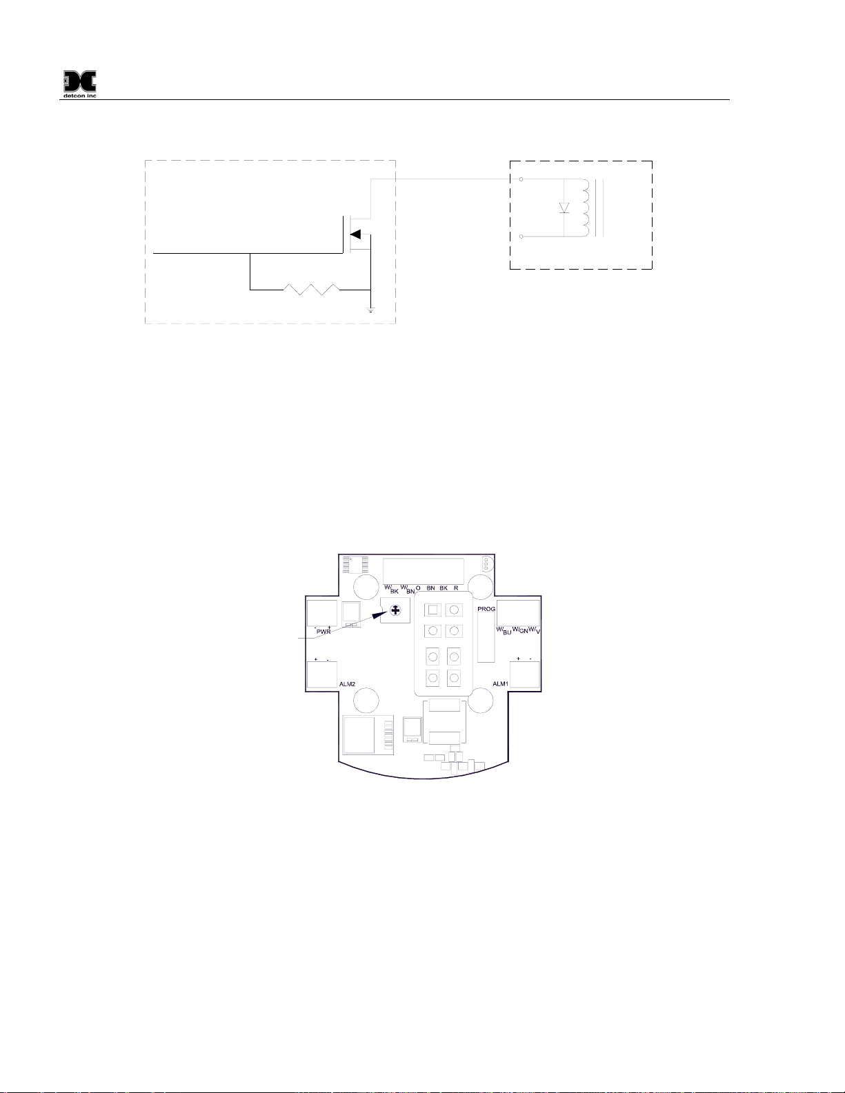
2.3.3 Alarm 1-4
Each RXT-300 wireless transceiver provides outputs for up to four alarms (Alarm 1, Alarm 2, Alarm 3 and
Alarm 4) which can drive relays on custom terminal boards provided by Detcon. The outputs are controlled
by the RXT-300 based upon the configuration and current alarm state of the whole network. The outputs are
open drain and rated for up to 300mA at 50V (See Figure 12). They are not intended to drive alarm devices
directly, but rather to drive relay coils (interposing relays) which in turn will drive a higher current output.
When using interposing relays, the customer must protect the RXT-300 Alarm outputs against the voltage
spike that can be over 1000V when the relay is de-energized. This voltage spike will damage the Alarm output
since it is well over the rated maximum voltage of 50V and will cause the output to fail. A transient protection
diode (1N4001 or equivalent) can be placed across the relay coil to mitigate the voltage spike.
NOTE: External relays used with this circuit must not exceed voltage/current requirements
and must have transient protection to minimize the voltage spike when the coil is de-energized.
RXT-300 SmartWireless™
RXT-300 Wireless IM Rev. 2.0 Page 14 of 41
49.9K
RXT-300
Relay
Coil
Alarm Output
V+
1N4001
Diode
MOSFET N-CH
50V 300mA
From RXT-300
Processor Output
Interposing Relay
Figure 12 Internal Alarm Output Circuit
Detcon alarm terminal boards are available that allow either AC or DC/Battery operation with the relays built
onto the board. These boards provide a complete solution to connecting an RXT-300 to power and providing
high-current relay closures. Figure 13 shows as an example, the DC/Battery Alarm board that take two of the
four RXT-300 Alarm outputs and generates two 24VDC outputs to drive audio and/or visual alarms. Any two
of the four Alarm outputs can be used and will be based on how alarms are configured for the system. This
board is designed to operate off of the 12VDC Detcon Smart Battery pack.
Alarm 2
Wiring Alarm 1
Wiring
Wiring to/from
Transceiver
Wiring to/from
Transceiver
External
24VDC
Connections
Rotary Switch
for Modbus
Address
0
1
2
3
4
5
6
7
8
9
A
B
C
D
E
F
Figure 13 DC/Battery Alarm Board
2.3.4 4-20mA A & B
The RXT-300 supports up to two 4-20mA signal inputs (A and B) used for monitoring 4-20mA devices (See
Figure 14). For the primary 4-20mA signal input, use A (green wire). For the secondary 4-20mA signal input,
use B (yellow wire). The input values are continuously read by the RXT-300 and stored in registers accessible
locally through two Modbus™ registers. During system configuration, these registers can be assigned to
sensors and the RXT-300 will then monitor and report on any alarm conditions.
Readings on a 4-20mA input are converted to representative values, for example, 4mA is read as a value of
400 and 20mA is read as a value of 2000. These inputs present a load of 162 ohms to ground so a current of
20mA will develop around 3.4V across the input and ground. This will consume a third less power versus the
250 ohm load used in other implementations. The inputs are protected for voltages up to 30V but the input
Table of contents


