6
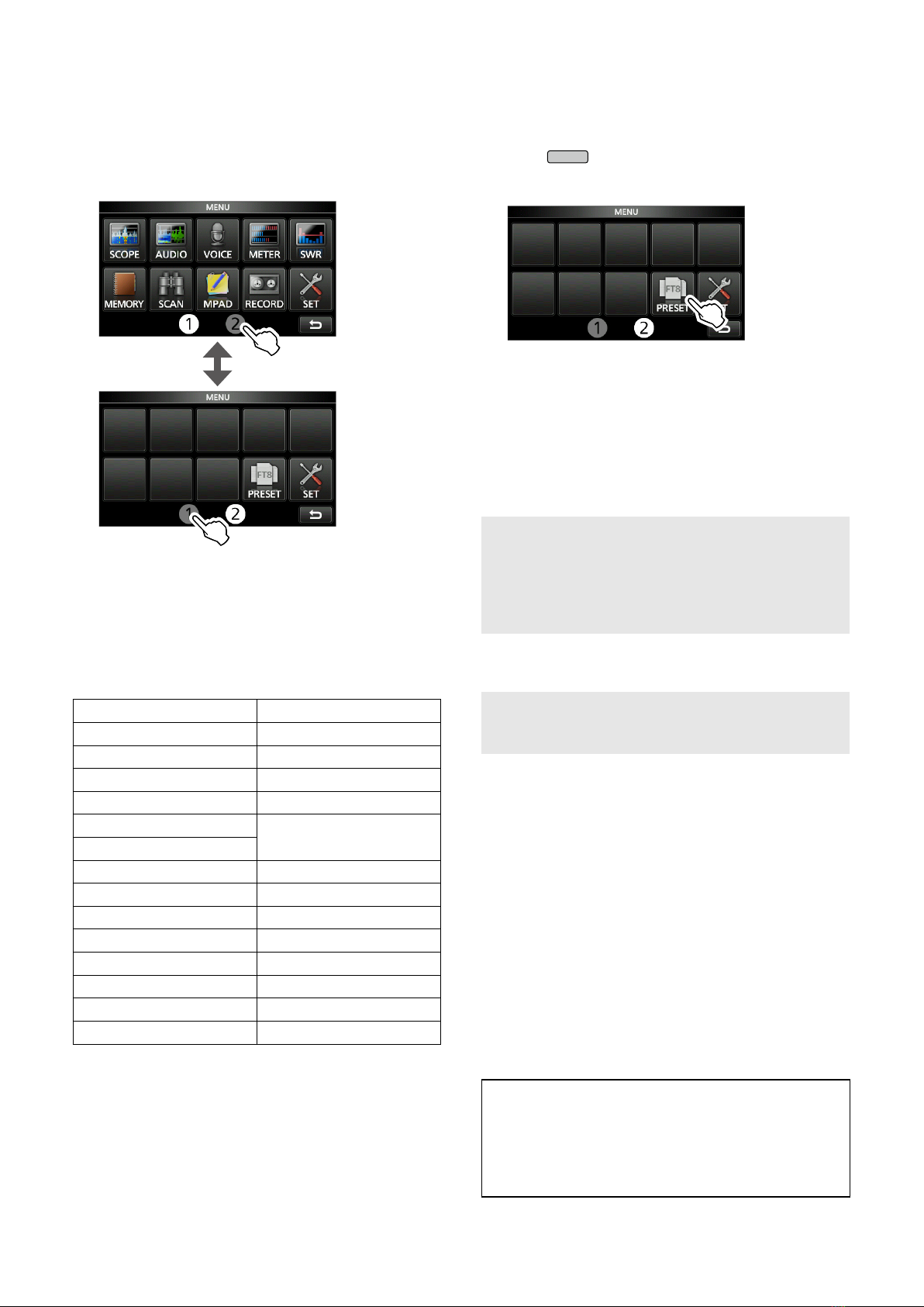
■MIC Key Customize function
You can change the microphone’s [UP]/[DOWN] keys
function.
» SET > Function > MIC Key Customize
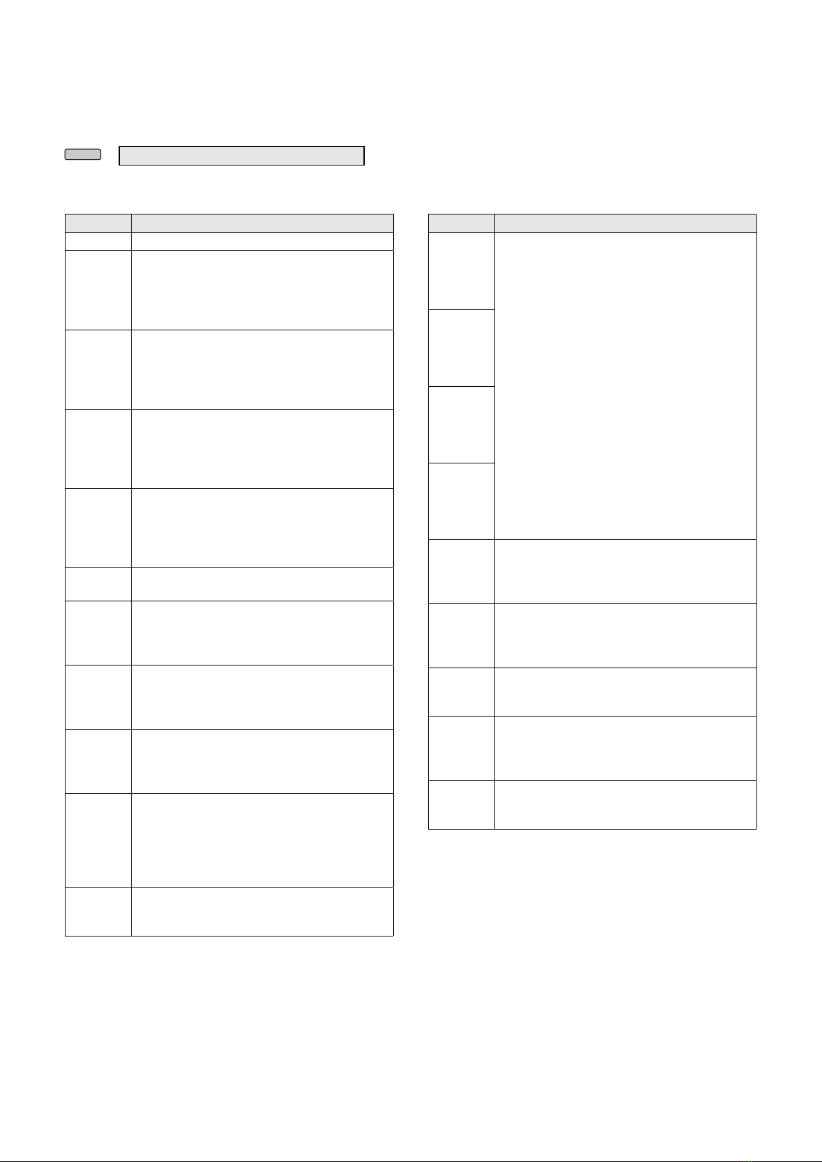
[UP] (Default: UP (VFO: kHz))
[DN] (Default: DOWN (VFO: kHz))
Function Description
--- No function
UP
Push to increase the frequency (in 50 Hz
steps*), or Memory channel.
* When the Tuning Step function is ON,
increases the frequency in the selected
Tuning Step.
DOWN
Push to decrease the frequency (in 50 Hz
steps*), or Memory channel.
* When the Tuning Step function is ON,
increases the frequency in the selected
Tuning Step.
UP
(VFO: kHz)
Push to increase the frequency (in 1 kHz
steps*), or Memory channel.
* When the Tuning Step function is ON,
increases the frequency in the selected
Tuning Step.
DOWN
(VFO: kHz)
Push to decrease the frequency (in 1 kHz
steps*), or Memory channel.
* When the Tuning Step function is ON,
increases the frequency in the selected
Tuning Step.
XFC While holding down the key, the transceiver
monitors signals.
VFO/MEMO
• Push to select the VFO mode and the
Memory mode.
• Hold down for 1 second to copy a Memory
channel contents to the VFO.
BAND UP
In the VFO mode
• Push to increase an operating band.
• Hold down for 1 second to recall the Band
Stacking Register contents.
BAND
DOWN
In the VFO mode
• Push to decrease an operating band.
• Hold down for 1 second to recall the Band
Stacking Register contents.
SPEECH
Push to announce the S-meter level,
frequency, or operating mode.
LIn the VFO or Memory mode, the frequency
and the operating mode are announced.
LS-meter level is announced only when the
S-level SPEECH function is ON.
MODE
• Push to select the operating mode.
• Hold down to toggle USB and LSB, CW and
CW-R, or RTTY and RTTY-R.
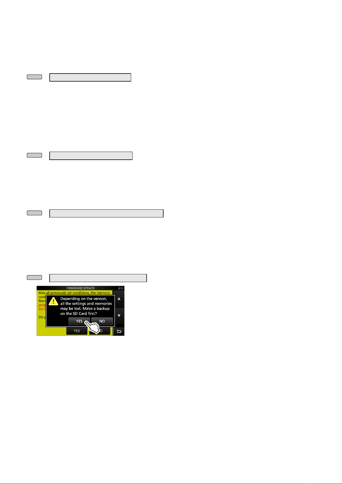
Function Description
Voice/
Keyer/
RTTY
Memory 1
In the SSB, AM, or FM mode
• Push to transmit the voice audio recorded
on the SD card once.
• Hold down for 1 second to repeatedly
transmit the voice audio.
LIf the voice audio is not saved in the Voice
TX memory (T1 ~ T4), this function is
disabled.
In the CW mode
• Push to transmit the Keyer memory content
once.
• Hold down for 1 second to repeatedly
transmit the memory content.
LIf the Keyer memory content (M1 ~ M4) is
not entered, this function is disabled.
In the RTTY mode
Push to transmit the RTTY memory content
once.
LIf the RTTY memory content (RT1 ~ RT4) is
not entered, this function is disabled.
Voice/
Keyer/
RTTY
Memory 2
Voice/
Keyer/
RTTY
Memory 3
Voice/
Keyer/
RTTY
Memory 4
TS
• Push to turn the Tuning Step function ON or
OFF.
• Hold down for 1 second to open the TS
screen.
MPAD
• Push to sequentially call up the contents in
the Memo Pads.
• Hold down for 1 second to save the
displayed contents into the Memo Pad.
SPLIT
• Push to turn the Split function ON or OFF.
• Hold down 1 second to turn ON the Quick
Split function.
A/B
• Push to select the VFO A or VFO B.
• Hold down for 1 second to set the displayed
VFO’s frequency to the VFO that is not
displayed.
TUNER
• Push to turn the antenna tuner ON or OFF.
• While “TUNE” is displayed, hold down for 1
second to start manual tuning.