Deutronic DBL Series Manual

Deutronicstr. 5, D - 84166 Adlkofen, Germany
Tel.: +49 (0) 8707 920-0
Fax: +49 (0) 8707 1004
http://www.deutronic.com
Installation and Safety Instructions - DBL/SC Last updated: 02.11.2020 Page 1 of 11
Installation and Safety Instructions
Automotive Power Processor - DBL Series
SmartCharger - SC Series
Conditioning of lead-acid, lead-gel, AGM, fleece and lithium-ion accumulators
in 12 V vehicle electrical systems
1.
Introduction ......................................................................................................................................................................2
2.
Symbols ...........................................................................................................................................................................2
3.
Correct Use......................................................................................................................................................................2
4.
Warranty ..........................................................................................................................................................................3
5.
Unpacking ........................................................................................................................................................................3
5.1
Checking before First Use ......................................................................................................................................3
5.2
Disposing of the Packaging Material ......................................................................................................................3
5.3
Storage....................................................................................................................................................................3
6.
Requirements for the Installation Site..............................................................................................................................4
7.
Assembly / Operating Site ...............................................................................................................................................4
8.
Installation and Preparation for Operation.......................................................................................................................5
8.1
Mains Connection ...................................................................................................................................................5
8.2
Cable Routing .........................................................................................................................................................7
8.3
Communication Interfaces ......................................................................................................................................7
9.
General Operating Instructions........................................................................................................................................8
10.
Conditioning ................................................................................................................................................................9
10.1
Battery Installed in the Vehicle..............................................................................................................................10
10.2
Battery outside the vehicle....................................................................................................................................10
11.
Cleaning ....................................................................................................................................................................11
12.
Contact details ..........................................................................................................................................................11

Deutronicstr. 5, D - 84166 Adlkofen, Germany
Tel.: +49 (0) 8707 920-0
Fax: +49 (0) 8707 1004
http://www.deutronic.com
Installation and Safety Instructions - DBL/SC Last updated: 02.11.2020 Page 2 of 11
1. Introduction
The following installation and safety instructions must be observed before putting an Automotive Power Processor from
the DBL Series or SmartCharger from the SC Series (hereinafter referred to as ‘device’) into operation.
These instructions contain important information for the user so that they will recognize potential hazards and minimize
the risk of physical and material damage.
This document makes no claim of completeness and takes account of the hazards known to the manufacturer.
This device must only be operated by qualified and trained specialist personnel.
The model-specific data sheets, the detailed operating instructions for the device model in question and the specifications
of the battery manufacturer must also always be adhered to.
These instructions should be kept in an easily accessible place.
2. Symbols
The safety and warning symbols used have the following meanings:
D
EVICE
L
ABEL
D
EVICE AND
D
OCUMENTATION
L
ABEL
Read the operating instructions
Information
Warning - electrical voltage
Note
Warning - hot surface
General warning sign
3. Correct Use
The device is intended solely for industrial use - especially for industrial applications in the automotive sector and their
affiliated specialist workshops. It should not be used for any other purpose (e.g. in private homes).
The device is designed for the conditioning of 12 V vehicle batteries and for the support of 12 V vehicle electrical
networks.
The device must only be installed and operated by qualified and trained specialist personnel.

Deutronicstr. 5, D - 84166 Adlkofen, Germany
Tel.: +49 (0) 8707 920-0
Fax: +49 (0) 8707 1004
http://www.deutronic.com
Installation and Safety Instructions - DBL/SC Last updated: 02.11.2020 Page 3 of 11
4. Warranty
Deutronic Elektronik GmbH points out that any warranty claim will be rendered invalid if:
•The device is opened and / or the seal is damaged.
•Mechanical or electrical modifications have been made to the device.
•The device is operated under incorrect conditions.
•The prohibited actions and information in these instructions are not observed.
•Accessories that are not authorized by Deutronic Elektronik GmbH are used.
5. Unpacking
5.1 Checking before First Use
•The delivery should be checked immediately upon receipt to ensure it is complete and to check for any
transport damage, such as mechanical damage to the device housing, as well as to any cables or accessories.
•If damage is present, this must be communicated to the transport company without delay.
•If damage is found or suspected on the device, its cables or accessories, the installation and commissioning
processes must not, under any circumstances, be continued.
•In this case, the device must be labeled as faulty.
•The device must no longer be used after a hard knock or fall.
5.2 Disposing of the Packaging Material
•Used packaging material should be kept in case it needs to be reused.
•If this is not possible, it must be disposed of appropriately and in an environmentally responsible way taking
account of applicable environmental protection guidelines.
5.3 Storage
•If stored incorrectly or inappropriately, the device can become damaged.
•Protect the device from dirt, moisture and extreme temperatures during storage.
•If the device has been stored for a prolonged period, check that it is functioning correctly before using it again.

Deutronicstr. 5, D - 84166 Adlkofen, Germany
Tel.: +49 (0) 8707 920-0
Fax: +49 (0) 8707 1004
http://www.deutronic.com
Installation and Safety Instructions - DBL/SC Last updated: 02.11.2020 Page 4 of 11
6. Requirements for the Installation Site
•The device must only be operated in the ambient conditions specified in the device data sheet.
•The device must be operated on a mechanically stable and non-flammable base.
•Adequate ventilation must be provided at all times at the installation site.
•Do not install or operate the device in the same area as the battery to be conditioned.
The distance between the battery and the device should be as great as possible, using the maximum cable
length available.
•Avoid installations where the device is operated directly above or below the battery to be conditioned. Rising
corrosive gas or dripping electrolyte may damage the device. Never place a battery directly on the device.
•Label the device's installation site with suitable warning notices and prohibition signs.
•Care must be taken to ensure that no metallic objects are able to fall between the battery terminals
(short circuit hazard).
•Installation and operation near radiators or similar sources of heat is prohibited.
•There must be no flammable materials within a radius of at least 2.5 meters around the device.
•The device must not be operated near aggressive vapors, in areas at risk of explosion or in the vicinity of
sources of ignition.
•When operated in environments where the presence of explosive gasoline vapors cannot be excluded, the
device must not be installed directly on the floor. A distance (installation site above the floor) of at least 45 cm
must always be maintained.
7. Assembly / Operating Site
•The device must only be operated in the operating site described in the data sheet.
•The user bears sole responsibility for the proper setup and safety of the equipment.
•Suitable mounting kits that have been approved by Deutronic are available from www.deutronic.com.
•Only use mounting kits approved by Deutronic.
•The device must be mounted so that operation is possible at any time and the user is able to read the status
of the device.
•If installed incorrectly, there is a risk of injury from the device toppling over.
•It is forbidden to make mechanical changes to the device, such as the drilling of holes for attaching additional
mounting points.
•Any modifications to the device can result in lethal operating states or fires.

Deutronicstr. 5, D - 84166 Adlkofen, Germany
Tel.: +49 (0) 8707 920-0
Fax: +49 (0) 8707 1004
http://www.deutronic.com
Installation and Safety Instructions - DBL/SC Last updated: 02.11.2020 Page 5 of 11
8. Installation and Preparation for Operation
8.1 Mains Connection
•The type plate is located - depending on the device version - either on the side, back or front of the device.
•The device is designed according to safety class 1 and must be permanently connected via the mains cable
used to the earth wire of the building installation.
•Before putting the device into service, have the correct earth connection checked by a qualified electrician.
•The mains voltage and mains frequency must match the information on the type plate.
•Do not replace removable mains cables with inadequately dimensioned ones.
•Without an earth connection, there is a danger of electric shock.
Fuse
•A building-side fuse in accordance with state-of-the-art technology is the responsibility of the user.
•Use a back-up fuse with a slow-trip characteristic and dimension it according to the maximum rated current
indicated on the device’s type plate or the data sheet.
•Use automatic fuses with characteristic B.
Mains Disconnection
•The mains disconnection can be carried out via the mains plug or the device plug.
•Devices that are operated on a 1 AC supply mains network will, depending on the version of the device
in question, feature an On / Off switch and can, in the event of a fault up to the internal device socket,
be disconnected from the mains.
•Devices operated on a 3 AC supply mains network do not have a switch on the device.
•For devices operated on a 3 AC supply mains network, an easily reachable 3-phase circuit breaker must be
provided during installation.
The circuit breaker must be labeled so that it can be clearly attributed to the device.
•In the event of a fault, the mains supply to the device must always be also be disconnected from the building
installation and the system secured against being switched back on.
Connecting Devices with a Rated Connected Voltage of 120 V AC
•These devices are intended for use on a rated 1 AC - 120 V network and have a connecting plug.
•Additional earth cables cannot be connected.
•Comply with country-specific regulations during installation and use of the mains connection cable.
•Operation is only permitted at a wall socket with a PE connection.
(Exception: See Information regarding Operation on IT Networks)

Deutronicstr. 5, D - 84166 Adlkofen, Germany
Tel.: +49 (0) 8707 920-0
Fax: +49 (0) 8707 1004
http://www.deutronic.com
Installation and Safety Instructions - DBL/SC Last updated: 02.11.2020 Page 6 of 11
Connecting Devices with a Rated Connected Voltage of 230 V AC
•These devices are intended for use on networks with more than one rated input voltage of 1 AC / 120 V
and have been equipped by the manufacturer with special connecting cables and country-specific plugs.
•Additional earth cables cannot be connected.
•Comply with country-specific regulations during installation and use of the mains connection cable.
•Do not use a mains adapter.
•Operation is only permitted at a wall socket with a PE connection.
(Exception: See Information regarding Operation on IT Networks)
Locking the Mains Plug
•Before putting the device into service, check the locking mechanism - if fitted - on the device-side mains input
to ensure it is secure.
Connecting Devices with a Rated Connected Voltage of 400 V AC / 480 V AC
•All devices with a rated connected voltage of 400 V AC / 480 V AC are designed for connection to networks
with star point earthing.
Operation on other types of network (such as phase-earthed triangular networks / delta networks)
is not permitted.
•The scope of supply includes only the device-side plug, not the opposite plug for the connecting cable.
The opposite plug is available as an optional accessory.
•Details of the potential connection options can be found in the data sheet of the device in question.
•A 3-pole, 16 A circuit breaker with B characteristics must be positioned externally upstream of every device.
•The pin assignment on the device-side mains connection socket must not be altered!
•If there is any damage to the sealing varnish applied at the factory, the warranty will be rendered void.
Information regarding Operation on IT Networks
•The device's data sheet must be consulted to determine whether the device in question may be operated
on IT networks.
•The operator is responsible for professional installation.
•The device does not have internal insulation monitoring.
•When the device is operated on un-earthed IT networks, external insulation monitoring is absolutely essential.

Deutronicstr. 5, D - 84166 Adlkofen, Germany
Tel.: +49 (0) 8707 920-0
Fax: +49 (0) 8707 1004
http://www.deutronic.com
Installation and Safety Instructions - DBL/SC Last updated: 02.11.2020 Page 7 of 11
8.2 Cable Routing
•Suitable and approved accessories for the connection to the supply network and the DC high-current output
are available from www.deutronic.com.
•Only use cables, plugs and accessory parts approved by Deutronic Elektronik GmbH.
•None of the cables connected to the device must touch the device housing and under no circumstances must
they be routed over the top of bottom of the device. This is to prevent damage due to hot surfaces.
•Cables should be routed exposed to the air for better cooling.
•Damaged cables and wires must be replaced immediately!
Until the repair work is completed, the device must be taken out of service and secured against being
switched back on.
•Use empty conduits or bushings if cables have to be routed through sheet metal walls or along other
sharp-edged parts to avoid mechanical damage.
•Route all cables so that they do not pose a trip hazard, cause damage or produce mechanical stress.
Cables must never be routed sharply kinked.
•Damaged cables can lead to fires and electric shock.
Overheating of the cable insulation can be caused by:
oHot surfaces on the housing
oWinding or bundling of the mains connection cable and DC output cables
oShared routing of the mains connection cable and DC output cables in the same installation channel
EMC-Compliant Cable Routing
•For reasons of electromagnetic compatibility (EMC), the mains connection cable and DC output cables must
be routed as far a part from each other as possible. Ideally, the cables will be routed on opposite sides of the
housing away from the device without the cables actually touching the device housing.
•“DC+” and “DC-” cables for the high-current output must, for reasons of electromagnetic compatibility (EMC),
be routed as close as possible to each other and parallel to the consumer (battery or vehicle electrical system).
•Interface cables must only be connected to the device if they are shielded on both sides.
Interface cables should be routed separately from the mains connection cable and the DC output cables.
8.3 Communication Interfaces
•The device-internal interfaces are not galvanically separate from the secondary current circuit.
•When peripheral devices are connected to the interfaces, galvanic separation must be ensured by the user.

Deutronicstr. 5, D - 84166 Adlkofen, Germany
Tel.: +49 (0) 8707 920-0
Fax: +49 (0) 8707 1004
http://www.deutronic.com
Installation and Safety Instructions - DBL/SC Last updated: 02.11.2020 Page 8 of 11
9. General Operating Instructions
•The device must not be operated by children or persons with impaired mental, sensory or psychological
capabilities, with inadequate experience or with insufficient knowledge.
•The device must be kept out of the reach of children or persons with impaired mental, sensory or psychological
capabilities, with inadequate experience or with insufficient knowledge.
•When the device is being un-plugged, always pull the plug, not the cable.
•Before connecting the DC output cables to the device, check the sockets and plugs for any soiling. Only once
the device has been disconnected from the supply network should soiling be removed with a dry cloth.
•Check all plugs and cables for moisture before connecting them.
Never connect the device to the power network with wet hands.
•Disconnect the device from the supply network when no longer in use.
•Position the output terminals when the device is not in use so that no electrically conductive connection can
occur between the contacts.
•Do not touch both connecting terminals of the DC output at the same time while the device is in operation.
•Before switching the device on, the two DC output plug connections must be checked to ensure they are secure.
•If the DC output plug connections are loose, sparks can form and overheating can occur. This is a fire hazard.
•In an industrial environment or in the workshop, surfaces are frequently painted or (powder-) coated and
therefore initially non-conductive. Mechanical contact by the output terminals, however, can scratch off the
surface coatings and therefore make the contact point conductive. The result of this can be a short-circuit
and overheating. This is a fire hazard.
•During operation, this device can interfere with electronic implants (e.g. cardiac pacemaker) and thereby
endanger people.
•Smoking and naked flames are prohibited during operation.
•Never cover the device with objects when it is in operation. The heat that builds up can cause lasting damage.
This is a fire hazard.

Deutronicstr. 5, D - 84166 Adlkofen, Germany
Tel.: +49 (0) 8707 920-0
Fax: +49 (0) 8707 1004
http://www.deutronic.com
Installation and Safety Instructions - DBL/SC Last updated: 02.11.2020 Page 9 of 11
10. Conditioning
•The device is approved solely for the conditioning of lead-acid, lead-gel, AGM, fleece and lithium-ion
accumulators in 12 V vehicle electrical systems with the mode suitable for the accumulator in question.
•The rated capacity of the battery to be conditions must be greater than 1 Ah.
•Do not connect any other batteries (e.g. dry batteries) to the device.
•Note the battery manufacturer's specifications.
•A marine (boat) battery must be removed and only conditioned on land. For conditioning on board, special
devices designed for maritime use are required.
•US / Canadian regulations also require that the following information is given to the user:
Ensure there is no voltage present at the DC output before connecting the DC output terminals to the battery.
First connect the battery to the conditioning device before the connection to the supply network is established.
Conversely, the connection to the supply network must be disconnected before the DC load cable
is disconnected from the battery.
•The device has customer-specific conditioning programs and parameterization options.
Choose the correct conditioning program for lead-acid, lead-gel, AGM, fleece and lithium-ion accumulators
and note the current and voltage limits set.
•Note the applicable safety regulations, safety measures and requirements for handling batteries and room
facilities.
•Only condition batteries in “CHARGE MODE” or “AUTO MODE” as the parameters and monitoring functions
required for ensuring safe operation are only activated in these programs.
•During the conditioning process and during use, lead-
based batteries need water. With batteries that can have
their water topped up, check the fill level regularly. If the fill level is too low, top it up using distilled water only.
•Normally, the extensive
device protection functions prevent any unsafe operating states. Never leave batteries
unsupervised for long periods during the conditioning process.
•Remove jewelry on the hands or around the beck when working with the device or a battery to be conditioned.
•Output terminals and the battery terminals must not be connected by conductive objects, such as tools.
•An accidental short-circuit can cause severe burns.
•The connection and conditioning of freshly filled, frozen or faulty batteries is prohibited and
can lead to serious
physical injury and material damage.
•Loosening the connections to a battery can lead to spark formation when a DC output is active. In this case,
there is a risk of fire.
•In EPS (external power supply) mode, the battery monitoring functions are not active.
•Battery acid is corrosive. If battery acid makes contact with the eyes or skin, rinse immediately with plenty
of water and seek medical assistance straight away.
•With lead-based accumulators, there is a risk of explosion due to oxyhydrogen gas!
Therefore the procedure described below must be followed to the letter.

Deutronicstr. 5, D - 84166 Adlkofen, Germany
Tel.: +49 (0) 8707 920-0
Fax: +49 (0) 8707 1004
http://www.deutronic.com
Installation and Safety Instructions - DBL/SC Last updated: 02.11.2020 Page 10 of 11
10.1 Battery Installed in the Vehicle
•The positive (POS, P, +) battery terminal normally has a larger diameter than the negative (NEG, N, -)
battery terminal.
•Depending on the vehicle manufacturer / type, the negative terminal is usually connected to the chassis.
•Position the supply and DC output cables so that the any of damage from the hood, door or moving engine
parts is avoided.
•Keep away from the fan / rotor blades, V-belt, V-belt pulleys and other moving parts that could cause physical
injury or material damage.
•Do not connect the output terminal to the carburettor, fuel lines or other sheet metal components.
Choose a clean and paint-free metal section of the frame or engine block, capable of conducting electricity,
for the connection. Ensure good contact and ensure that the output terminals are secure.
•When interrupting the first connection, stay as far away from the battery as possible.
•Procedure:
oCheck the polarity of the battery connections.
oDetermine the battery terminal that is connected to the chassis.
oFollow the connection sequence accordingly.
See the following sections
oBefore disconnecting the DC lines, first ensure that the device has been disconnected from the supply
network.
oWhen disconnecting the charger, always work in the reverse sequence to the connection process.
For vehicles that are connected to the frame at the negative battery terminal
•First connect the device’s positive (red) terminal to the positive (POS, P, +) terminal on the battery.
•Then connect the negative (black) terminal to the chassis or engine block away from the battery.
For vehicles that are connected to the frame at the positive battery terminal
•First connect the device’s negative (black) terminal to the negative (NEG, N,-) terminal on the battery.
•Then connect the positive (red) terminal to the chassis or engine block away from the battery.
10.2 Battery outside the vehicle
•The positive (POS, P, +) battery terminal normally has a larger diameter than the negative (NEG, N, -)
battery terminal.
•Turn away from the battery when the final contact is made.
•Procedure:
oCheck the polarity of the battery connections.
oFirst connect the device’s positive (red) terminal to the positive (POS, P, +) terminal on the battery.
oFirst connect the negative (black) terminal to the negative (NEG, N,-) terminal on the battery.
oBefore disconnecting the DC lines, first ensure that the device has been disconnected from the supply
network.
oWhen disconnecting the charger, always work in the reverse sequence to the connection process.

Deutronicstr. 5, D - 84166 Adlkofen, Germany
Tel.: +49 (0) 8707 920-0
Fax: +49 (0) 8707 1004
http://www.deutronic.com
Installation and Safety Instructions - DBL/SC Last updated: 02.11.2020 Page 11 of 11
11. Cleaning
•Switching off with the mains switch on the device - which may be an optional feature, depending on the device -
is not sufficient.
Disconnect the device from the mains before cleaning.
•Cleaning must only be carried out with a slightly damp cloth and without the addition of chemicals.
12. Contact details
Deutronic Elektronik GmbH
Deutronicstrasse 5
84166 Adlkofen / Germany
Tel.: +49 (0)8707 / 920-0
Fax: +49 (0)8707 / 1004
E-mail: sales@deutronic.com
http://www.deutronic.com
DC No. 33587
This manual suits for next models
1
Table of contents
Popular Automobile Accessories manuals by other brands
Blue Ox
Blue Ox BX1133 installation instructions

Fabtech
Fabtech FTS8002 installation instructions

Monster
Monster iCarPlay Direct Connect 2000 User guide & warranty information

Thule
Thule Single Step V10 instructions

Bury technologies
Bury technologies CC 9048 quick guide
Mazdaspeed
Mazdaspeed QSEA 51 96Z Installation and user instructions

Bosch
Bosch 1 987 432 017 installation instructions
TruckCraft
TruckCraft TC-508 owner's manual

Kolpin Outdoors
Kolpin Outdoors 25-8810 Assembly & owners manual
Metra Electronics
Metra Electronics 2004-2009 99-3303 Applications

Maxon
Maxon GPC X1-LDF installation manual
Nav TV
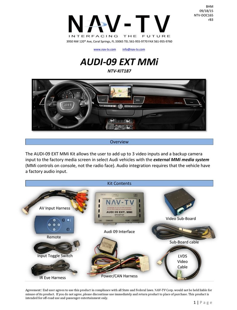
Nav TV NTV-KIT187 quick start guide
