Deutronic SmartCharger Series User manual
Deutronicstr. 5, D - 84166 Adlkofen, Germany
Tel.: +49 (0) 8707 920-0
Fax: +49 (0) 8707 1004
http://www.deutronic.com
SmartCharger Operating Instructions / MPC6.1 Last updated: 02.07.2020 Page 1 of 16
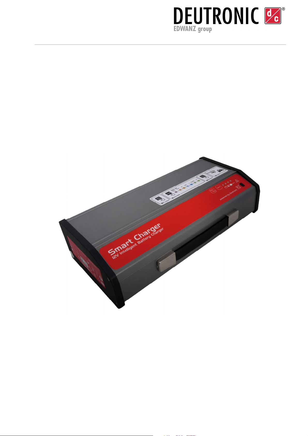
SmartCharger Series
Operating Instructions
- Valid from device firmware version 02.00.013 -
Suitable for 12 V DC vehicle electrical networks / batteries
Illustration similar
Important note
This device must only be used by qualified, specialist personnel for its specified application. Read
the operating instructions carefully and comply in all cases with the safety instructions and the
specifications of the battery manufacturer!
Depending on any customer-specific delivery specifications, the parameters described may differ
or some modes may not be available. If you have any questions regarding the parameterization
of your device, please contact Deutronic Elektronik GmbH or one of our worldwide service centers.

Deutronicstr. 5, D - 84166 Adlkofen, Germany
Tel.: +49 (0) 8707 920-0
Fax: +49 (0) 8707 1004
http://www.deutronic.com
SmartCharger Operating Instructions / MPC6.1 Last updated: 02.07.2020 Page 2 of 16
Contents
1. Installation and Safety Instructions ..................................................................................... 3
2. Assembly............................................................................................................................ 3
2.1. Mains Connection........................................................................................................... 3
2.2. Charging cable ............................................................................................................... 3
3. Control elements................................................................................................................. 4
3.1. Control panel .................................................................................................................. 4
3.2. Buttons ........................................................................................................................... 4
3.3. Signaling......................................................................................................................... 5
3.3.1. Standby mode................................................................................................... 5
3.3.2. Active mode ...................................................................................................... 5
4. Commissioning ................................................................................................................... 7
4.1. Preparing the charging cables for use in showrooms...................................................... 8
4.2. Initial setup ..................................................................................................................... 9
5. Operating modes .............................................................................................................. 10
5.1. Cable compensation ..................................................................................................... 10
5.2. Charging Pb LTC / Charging Li / LFP LTC.................................................................... 10
5.3. Charging Pb / ChargingLi/LFP ...................................................................................... 11
5.4. PowerUp....................................................................................................................... 12
5.5. EPS (external power supply) ........................................................................................ 13
6. Error messages ................................................................................................................ 14
6.1. Signaling....................................................................................................................... 14
6.2. User Errors and Resolution........................................................................................... 14
7. Service Center / Repairs................................................................................................... 16
8. Warranty Disclaimer ......................................................................................................... 16
9. Contact details.................................................................................................................. 16
Device features
Extensive protection and self-protection functions
Short-circuit and reverse polarity protection
Vehicle electronics/airbag protection
Protective function in the event of battery defects
Spark suppression
Cable compensation
Depending on the customer-specific requirements, various operating modes are available ex works
Operating modes: Pb-LTC (long-term charging), Pb charging,
Li/LFP-LTC (long-term charging), Li/LFP charging,
PowerUp and external power supply (EPS/buffer mode).

Deutronicstr. 5, D - 84166 Adlkofen, Germany
Tel.: +49 (0) 8707 920-0
Fax: +49 (0) 8707 1004
http://www.deutronic.com
SmartCharger Operating Instructions / MPC6.1 Last updated: 02.07.2020 Page 3 of 16
1. Installation and Safety Instructions
In addition to the operating instructions, always also comply with the specifications of the battery
manufacturer, the associated installation and safety instructions and the device-specific data
sheets.
The installation and safety instructions, as well as the data sheets, can be found on our website
at www.deutronic.com. Alternatively, please contact Deutronic Elektronik GmbH or one of our
worldwide service centers
2. Assembly
2.1. Mains Connection
The device may only be used with a suitable mains power cable or country-specific adapter.
If an extension lead is used, the correct cable cross section must be selected according to the
following table:
Cable length [feet] 25 50 100 150
AWG sizes 18 16 12 10
Cable length [meters] 7 15 30 45
Cable cross-section [mm²] 1.0 1.5 4 6
Table with the recommended AWG sizes as well as the minimum cable cross section for extension leads
2.2. Charging cable
If the charging cable is changed, cable compensation must always be carried out. Even if the cable
is exchanged for a cable of the same type, cable compensation must be carried out (see Section 5.1).

Deutronicstr. 5, D - 84166 Adlkofen, Germany
Tel.: +49 (0) 8707 920-0
Fax: +49 (0) 8707 1004
http://www.deutronic.com
SmartCharger Operating Instructions / MPC6.1 Last updated: 02.07.2020 Page 4 of 16
3. Control elements
3.1. Control panel
The control elements, incl. LEDs and buttons, are shown below:
Figure
1
:
Control panel
[1]
Status LED
(Color depends on operating mode)
[2]
BAT full (green LED)
[3]
BAT half-full (yellow LED)
[4]
BAT empty (yellow LED)
[5]
MODE button
For changing the operating mode
[6]
START / STOP button
3.2. Buttons
START / STOP button:
In “Standby” mode, pressing the START/STOP button will activate the selected operating mode.
Pressing the button again will put the device back into “Standby” mode.
MODE button:
In “Standby” mode, pressing the MODE button will change the operating mode.
Note: Changing between the operating modes is not possible in Active mode!

Deutronicstr. 5, D - 84166 Adlkofen, Germany
Tel.: +49 (0) 8707 920-0
Fax: +49 (0) 8707 1004
http://www.deutronic.com
SmartCharger Operating Instructions / MPC6.1 Last updated: 02.07.2020 Page 5 of 16
3.3. Signaling
Note: Depending on any customer-specific delivery specifications, the parameters described may differ
or some modes may not be available. If you have any questions regarding the parameterization of your
device, please contact Deutronic Elektronik GmbH or one of our worldwide service centers.
3.3.1. Standby mode
Operating mode Status LED LED 2 LED 3 LED 4
Cable compensation Illuminated solid violet Flashing Flashing Flashing
Charging Pb LTC Flashing orange Flashing Flashing Flashing
Charging Pb Illuminated solid orange Flashing Flashing Flashing
Charging Li LTC Flashing blue Flashing Flashing Flashing
Charging Li Illuminated solid blue Flashing Flashing Flashing
PowerUp Flashing green Flashing Flashing Flashing
EPS Illuminated solid green Flashing Flashing Flashing
3.3.2. Active mode
Operating mode: Cable compensation
State Status LED LED 2 LED 3 LED 4
Load detection active Illuminated solid violet Flashing
Switch-on delay Illuminated solid violet Flashes quickly
Cable compensation
active Illuminated solid violet Chaser
(each LED lights up for 1 second)
Operating mode: Charging Pb LTC (long-term charging)
State Status LED LED 2 LED 3 LED 4
Load detection active Flashing orange Flashing
Switch-on delay Flashing orange Flashes quickly
Standard Flashing orange Chaser
(each LED lights up for 1 second)
Monitoring
Battery full
Flashing orange Solid
Battery half-full
Flashing orange Solid
Battery empty
Flashing orange Solid
Table of contents
Popular Camera Accessories manuals by other brands


Trojan
Trojan GC2 48V quick start guide

Calumet
Calumet 7100 Series CK7114 operating instructions

Ropox
Ropox 4Single Series User manual and installation instructions

Cambo
Cambo Wide DS Digital Series Main operating instructions

Samsung
Samsung SHG-120 Specification sheet

Ryobi
Ryobi BPL-1820 Owner's operating manual