Deutscher H660 User manual

OWNER’S MANUAL
H660

SAFETY INSTRUCTIONS!
BEFORE STARTING:
•Know your controls. Read the owners manuals thoroughly. Learn how to stop the engine
quickly in an emergency.
•Inspect the area to be mown, remove all debris and obstacles that may be in the path of the
mower. Do not attempt to shift obstacles while mower is going.
•Apply sunscreen; wear appropriate clothing, a hat and sunglasses to avoid sunburn.
•Damaged blades and worn bolts are major hazards. Before starting, always visually
inspect to see that blades, blade bolts and cutter assemblies are not worn or damaged.
Replace worn or damaged blades and bolts in sets top preserve balance.
•Do not allow children or people unfamiliar with these instructions to use the mower.
•With prolonged use, hearing protection should be worn.
•Never mow while barefoot or wearing open sandals, or thongs. Wear long trousers and
heavy shoes.
•It is advisable to wear suitable eye protection when operating the mower.
•Refuel outdoors only. Do not smoke while refuelling engine. Add fuel before starting the
engine. Never remove cap off the fuel tank or add petrol while the engine is running or the
engine is hot. If petrol is spilled, do not attempt to start the engine but move the machine
away from the area of the spill and avoid creating any source of ignition until the petrol
vapours have dissipated.
STARTING:
•Disengage all blades and drive clutches and shift gear lever into neutral before starting the
engine.
•Start the mower carefully according to instructions and with feet well away from blades and
not in front of the discharge chute.
OPERATION:
•Never mow while people, especially children, or pets are nearby.
•Mow only in daylight or in good artificial light. Stay alert for holes in the terrain and other
hidden hazards.
•Never direct discharge of material towards bystanders.
•Avoid operating the equipment in wet grass, where feasible.
•Do not put hands and feet near or under rotating parts. Keep clear of the discharge opening
at all times.
•Never pick up or carry a mower while the engine is running.
•Use extreme caution when reversing or pulling mower towards you.
•Do not carry passengers.
•Walk, never run.
•Slopes:
Do not mow excessively steep slopes.
Exercise extreme caution when on slopes.
For pedestrian controlled mowers, mow across the face of slopes, never up and down and
exercise extreme caution when changing direction on slopes.
•Use low throttle settings when engaging the ground drive, especially in high gears.
Reduce speed on slopes and in sharp turns to prevent overturning or loss of control.
•Stop the blades when crossing surfaces other than grass and when transporting the mower
to and from the area to be mowed.
•Do not operate the engine in a confined space where dangerous carbon monoxide fumes
can collect.
•Stop the engine:
Whenever you leave the mower, even for an instant.
Before refuelling.
•Stop the engine and disconnect the spark-plug lead, or turn off and remove key:
Before clearing blockages or unclogging chute:
Before checking, cleaning or working on the mower:
After striking a foreign object, inspect the mower for damage and make repairs before
restarting and operating the mower:
If mower starts to vibrate abnormally stop the engine immediately.

2
•Use care when pulling trailing seat,
Use only approved drawbar hitch points. Do not use on public roads.
Do not turn sharply; use care when reversing.
•Watch out for traffic when crossing or near roadways.
•Before leaving the operator’s position:
Disengage the cutter engagement lever,
Change into neutral and set the parking brake,
Stop the engine and or remove key.
•Do not modify mower in any way, or use the mower with out the
shields and guards in place, they are for your protection.
MAINTENANCE and STORAGE:
•Keep all nuts, bolts and screws tight to be sure the equipment is in safe working condition.
•Do not use pressure-cleaning equipment.
•Never store the equipment with petrol in the tank inside a building where fumes can reach
an open flame or spark.
•Allow the engine to cool before storing in any enclosure.
•To reduce the fire hazard, keep the engine, silencer, battery compartment and petrol
storage are free of grass, leaves, or excessive grease.
•Replace worn or damaged parts for safety;
•Replace faulty silencers.
•If the fuel tank has to be drained, do this out-doors.
•Do not change the engine governor settings or over speed the engine. Operating an engine
at excessive speed can increase the hazard to personal injury.
•Be careful during adjustment of the mower to prevent entrapment of the fingers between
moving blades and fixed parts of the mower.
•Store fuel in a cool place in a container specifically designed for the purpose. In general,
plastic containers are unsuitable.
•When the mower is to be parked, stored or left unattended, lower the cutting deck.
SPECIFICATIONS:
ENGINE: Honda and Briggs and Stratton engines are used, see engine owner’s manual supplied
with the mower.
GEARBOX: Deutscher HD120, with two forward gears and reverse, incorporating a differential
gearbox in an oil bath alloy housing.
Recommended oil EPX 85w/140
Capacity: 750ml
SPEED RANGE: Low gear: 2.18kph @ 2500rpm.
High gear: 4.18kph @ 2500rpm.
Reverse gear: 1.67kph @ 2500rpm.
TYRES: Rear: 13-500-6 Pressure, 20psi
Front 250 x 4 Pressure, 20psi
CUTTING HEAD: 660mm cut, 2 x blades,
6 cutting hight positions from 30mm-88mm.
GENERAL: Length: 1600mm, Width: 640mm, Height: 960mm, Weight:120kg
3

CONTROLS: illus. 1
PRE-START CHECK:
Your Deutscher Mower comes to you tested and ready to operate, with engine and gearbox filled
with oil.
•Read all safety instructions and know how to stop engine quickly in any emergency.
•Know your controls –Where they are and their function.
•Use fresh unleaded petrol. Do not mix oil with petrol.
•Ensure drive and cutter mechanisms are placed in neutral or disengaged.
OPERATION:
TO START THE ENGINE (Manual start):
•When engine is cold, move throttle lever to CHOKE position.
•When engine is hot, move throttle lever to high throttle position.
•Slowly pull starter cord until starter pawls engage and rope stops then pull with force
to turn engine over, and release cord.
•Once engine is running shift throttle lever from Choke position to desired operating position.
TO STOP THE ENGINE:
•Push throttle lever to STOP position.
TO START THE ENGINE (Electric starter version):
•When engine is cold, move throttle lever to CHOKE position.
•When engine is hot, move throttle lever to high throttle position.
•Turn key to start position and release once engine is running.
•Once engine is running shift throttle lever from Choke position to desired operating position.
TO STOP THE ENGINE:
•Turn key to OFF position.
TO DRIVE MOWER:
•Release park brake.
•Select gear, Low forward: Raise and turn left LIFT
High forward: Raise and turn right LOW HIGH
Reverse: Push down and turn right
•Clasp clutch lever and hold to hand grip, releasing, N
to stop. WARNING! Use low throttle settings when
engaging the traction-clutch, especially in high gears. REV
DEPRESS
GEAR
SELECTOR
4 TO ENGAGE CUTTER DRIVE:
CLUTCH LEVER
RAISE & LOWER LEVER
CUTTER ENGAGEMENT ACTIVATOR
PARKING BRAKE ACTIVATOR
THROTTLE CONTROL LEVER
GEAR LEVER
Illus.1

•Set throttle setting to a position as not to stall engine on engagement.
•Place right foot on lever and press down and lock into position.
•To release, knock lever up with right foot.
It
•
MOWING ACROSS SLOPES AND REVERSING
•As mentioned in the Safety Instructions, reduce speed on slopes and in sharp turns to prevent
overturning and loss of control. Mow across the face of slopes, never up and down.
•Wear suitable boots for the terrain. Do not continue mowing if you are slipping while walking.
Exercise extreme caution if the grass is damp.
•Do not mow an area with a slope greater than 10 degrees to the horizontal.
•Be extremely cautious when reversing. This is particularly important on slopes. Wear non slip
footwear and keep well back from the mower to ensure your footing is steady. Instantly release
the drive lever if you feel yourself slipping.
•Ensure the engine is turned off AND THE PARKING BRAKE IS ENGAGED before leaving a
mower parked on a slope. This applies even if you leave the mower for an instant.
TRANSPORTING AND LIFTING THE MOWER
It is far safer to use ramps or a lifting device to put the mower onto a trailer or utility tray,
rather than attempting to lift it. Never attempt to lift the mower on your own.
5 MAINTENANCE:
ILLUS. 2
RELEASE
ENGAGE

LUBRICATION CHART
Lubrication. Daily 20hrs 100hrs
Engine, Refer engine manual.
Gearbox
Check X
Change Gear oil EPX 85w/145 X
Cutter spindle Grease X
King pins Grease X
Raise & lower frame slides Grease X
Gear control linkages Oil X
Clutch control linkages Oil X
Height control linkages Oil X
Throttle cable Oil X
GEARBOX:
Use gear oil 85w/140 Capacity = 750ml
CUTTER SPINDLE:
Grease every 20 hours until grease
comes out between grease cap and
spindle housing.
6
GEARBOX BELT: illus 6 REPLACEMENT
FILL GEAR BOX TO LEVEL PLUG
DRAIN PLUG
ILLUS. 3
ILLUS. 4

•Before any inspection or replacements of the belts and associated parts turn
engine off and pull spark plug lead off spark plug.
•Be careful during adjustment of the mower to prevent entrapment of the fingers
between moving blades and pulley’s fixed parts of the mower.
•Remove nut “A” from adjustment pivot and remove from crank arm.
•Remove belt from pulleys and slide over clutch adjustment rod.
•To fit new belt, place belt over clutch adjustment rod and rap around pulley’s.
•Replace adjustment pivot to crank arm and tighten nut “A”.
•Adjust clutch: See CLUTCH ADJUSTMENT.
CUTTER BELT: REPLACEMENT
•Before replacements of the belts and associated parts turn engine off and pull
spark plug lead off spark plug.
•Be careful during adjustment of the mower to prevent entrapment of the fingers
between moving blades, pulley’s and fixed parts of the mower.
•Remove belt guide (H57) by unbolting from engine mount.
•Remove gearbox belt from engine pulley.
•Ensure cutter belt is disengaged.
•Move cutter height lever to mid height position.
•Loosen “C” nut and brake lever stop to ensure belt is loose.
•Remove old belt and replace new belt feeding it around the pulleys and keeping the belt on
the inside of the guide pins.
•Place cutter in engaged position and adjust belt by adjusting nuts “C” & “B”.
•Belt should have 20mm slack. DO NOT OVER TIGHTEN!
•Adjust brake lever stop to ensure cutter spindle stops when disengaged.
•Replace gearbox belt and refit belt guide.( Note : Belt guide bolted inside engine mounting
plate.)
•Run and test to ensure all adjustments are correct.
7
CUTTER SPINDLE BRAKE: ADJUSTMENT
B
C
A
B
C
Illus. 6
ILLUS. 7

•Before replacements of the belts and associated parts turn engine off and pull
spark plug lead off spark plug.
•Be careful during adjustment of the mower to prevent entrapment of the fingers
between moving blades, pulley’s and fixed parts of the mower.
•Loosen nut holding brake lever stop to chassis and slide forward until brake pad
prevents cutter pulley from rotating when cutters are disengaged.
•Make sure brake pad is clear of cutter pulley when engaged.
•Tighten nut holding brake lever stop to chassis.
CLUTCH ADJUSTMENT FOR TRANSMISSION: See illus. 6
•Loosen nut “C” and tighten nut “B”.
•Make sure belt is entirely free when clutch lever is disengaged.
•DO NOT OVER-TIGHTEN BELT.
BLADES:
•Before any inspection or replacements of the blades and associated parts turn
engine off and pull spark plug lead off spark plug.
•Be careful during adjustment of the mower to prevent entrapment of the fingers
between moving blades and fixed parts of the mower.
•It is important that you visually inspect the blades, bolts and nuts to ensure that they are in
a safe operating condition; this should be done before each mowing period.
•Always replace blades and bolts in kit form as to prevent any vibrations that may damage
the mower and cause personal injury.
ILLUS. 5
8
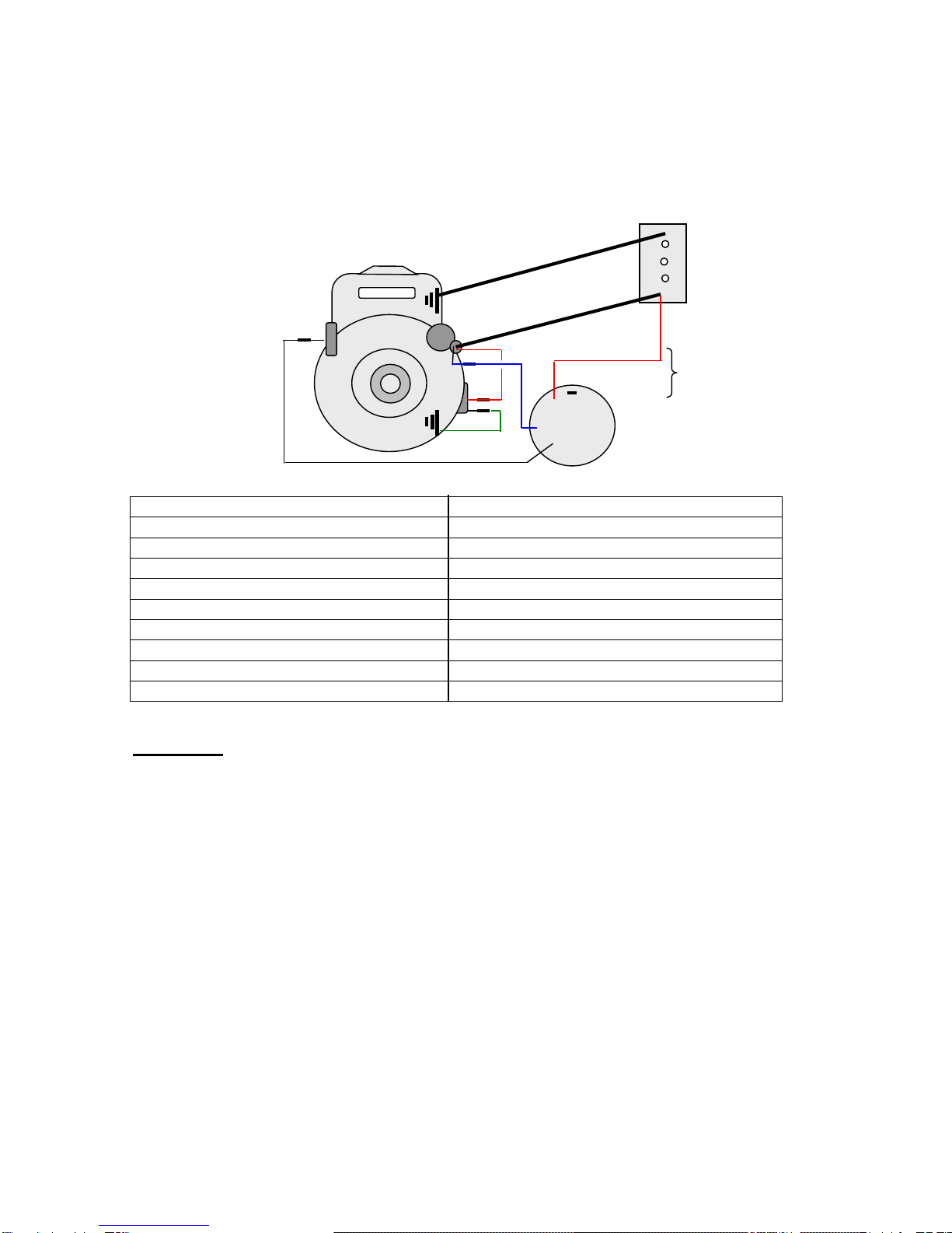
WIRING DIAGRAM:
HONDA GXV390K1 DAEU
-
2
3
7+
59 2
4 BLUE
6RED 11
RED
8 IBIG
10 GREEN IS
IMIL
BLACK 1
Illus. No. Part No. Description. Illus. No. Part No. Description.
1 T316 Key Switch 8 Regulator
2 R323 Cable 330mm 9 Starter Motor
3 H315 Battery 12volt 10 Earth, regulator
4 Solenoid, starter 11 R322 Loom assembly
5 Stop switch 12 T302 Solenoid
6 Engine 13 Alternator wire
7 Engine mount, Earth 14 R312 Cable 170mm
15 R324 Loom assembly
WARNING: Incorrect wiring may result in damage to the engines electrical system.
Only qualified and or competent electrical technicians should attempt any
repairs or alterations.

9 NOTES
WHEN ORDERING PARTS SPECIFY THE MODEL AND SERIAL NUMBER ON
THE NAME PLATE OF THE MOWER AND THE PART NUMBER IN THIS
MANUAL.
THE MANUFACTURES RESERVE THE RIGHT TO ALTER, CHANGE OR VATY THE
SPECIFICATIONS OF THE MACHINE OR ANY OF THE COMPONENT PARTS AT ANY TIME
WITHOUT NOTICE.

10
CHASSIS
ILLUS
PART No.
DESCRIPTION
ILLUS
PART No.
DESRIPTION
1
H600
Chassis
23
H06
Pulley, engine
2
H602
Rod, conn. Raise & low.
24
RD126
Key
3
H603
Rod, conn. R&L rear
25
H58
Plate, clutch pulley
4
H604
Top cover, B&S.
26
HD121
Wheel complete
-
H605
Top cover, Honda
27
T564
Tube 13-500-6
5
Y558
Bolt 8mm x 20
28
HD122
Tyre 13-500-6
6
H607
Spring washer 8mm
29
HD123
Rim
7
H608
Flat washer 8mm
30
HD79
Pin, axle drive
8
H609
Bush
31
H617
Activator, blades
9
H622
King pin & stub axle LH
32
H618
Rod, cutter engage.
10
H623
King pin & stub axle RH
33
H12
Brake rod
11
H624
Washer Brass
34
H50
Spring
12
H614
Lock pin
35
H03
Activator, brake
13
H506
Roll pin
36
H60
Bearing 6202drs
14
H615
Spring
37
H621
Bolt & nut
15
H512
Tyre 250-4
38
1512
Stepped bush
16
Y556
Rim & bearings
39
H61
Pulley
17
H513
Tube 250-4
40
H48
Pin, pivot
18
H616
Wheel complete
41
H47
Arm, crank
19
T588
Bearing 6203
42
H621
Bolt, pivot
20
D50
Spring
43
R13
Grease nipple
21
R87
Spring
44
H09
Gear box belt.
17
15
20
20
27
28
29
30
23
24
25
18
1
4
5
6
7
8
8
11
12
10
42
33
34
35
36
40
41
32
31
26
37
2
3
9
13
14
16
5,7,19
21
22
39
38
43
44
45

22
H63
Belt Guide
45
1429
Belt Guard (B&S)
11 CUTTER ASSEMBLY
ILLUS
PART No.
DESCRIPTION
ILLUS
PART No.
DESCRIPTION
1
D10
Pulley
15
G33
Bearing 30205
2
Y543
Brake pad
16
G34
Seal
3
H28
Brake lever
17
H29
Spindle & flange
4
H610
Main guard
18
H632
Push rod
5
H611
Side chute
19
H631
Connector, push rod
6
H612
Flap,
20
D50
Spring
7
H613
Hinge bar
21
R13
Grease nipple
8
Y537
Pin x 4
22
H27
Housing, spindle
9
H23
Nut x 4
23
D5/26
Blade plate
10
H19
Brake lever stop
24
G36
Bolt, blade plate x 3
11
H15
Spring
25
H650
Blade N,B,W x 2
12
G30
Lock nut
H651
Blade x 2
13
G31
Dust cap
H652
Nut,bolt & washer.x 2
14
G32
Spacer
26
R14
V-belt, cutter,B66
27
H20
Raise & Lower frame
H660
Cutting deck complete
H661
Main Guard Inc
23
1
2
3
4
5
6
26
10
11
8
12
13
14
15
21
22
7
15
16
17
18
19
20
24
25
9
27

chute & flap
12
HANDLE BARS & CONTROLS
ILLUS PART No DESCRIPTION ILLUS PART No DESCRIPTION
1 D130 Cable, throttle 12 D42 Knob, 3/8”id
2 H53 Gear lever 13 H57 Guide, g/box belt
3 Z08 Lever, throttle 14 H54 Collar
4 D19 Hand grip 15 H55 Spring
5 H627 Clutch lever 16 H56 Selector arm & ball
6 H46 Vert. Clutch rod 17 H69 Circlip, int.19mm
7 H628 Handle bars 18 H630 Bolt, nut & washer
8 H50 Spring 19 H52 Gear selector plate
9 H629 Height lever 20 H617 Activator, blades
10 Y13 Knob, ½” id 21 H621 Pivot bolt &nut
11 D134 Spring


13 GEARBOX ASSEMBLY
42

14 GEARBOX ASSEMBLY
LLUS
PART No
DESCRIPTION
QTY
ILLUS
PART No
DESCRIPTION
QTY
1
HD105
Screw, pulley
1
36
HD80
Selector tappet Forward
1
2
HD107
Key
1
37
HD81
Selector tappet reverse
1
3
H631
Spring washer
1
38
HD77
High crown gear
1
4
HD106
Washer
1
39
Z50
Bearing, needle, axle
4
5
HD108
Pulley
1
40
MRD179
Spacer, diff.
4
6
HD109
Spacer
1
41
HD76
Low crown gear
1
7
HD110
Seal 25x40x7
1
42
HD78
Axle
2
8
HD111
Circlip 40mm
1
43
HD75
Bolt, diff
4
9
HD112
Bearing 6203
1
44
HD84
Spring holder
2
10
HD113
Input spindle
1
45
HD83
Spring
2
11
HD104
Plug ¾” UNF
1
46
HD82
Ball
2
12
HD116
Fibre washer ¾”
1
47
HD103
Housing R.H.
1
13
RD194
Bearing roller B128
1
48
HD115
Sleeve, bearing
1
14
RD174
Nut, axle 5/8” UNF
2
49
HD92
Reverse gear 13 teeth
1
15
HD124
Spring washer
2
50
HD91
Bronze worm gear
1
16
RD175
Flat washer
2
51
HD114
Washer, hardened
1
17
DD90
Seal, axle 7/8”x1,3/8”x1/4”
2
52
HD90
High gear pinion & clutch
1
18
HD79
Drive pin, axle
2
53
HD88
Double clutch
1
19
MDD98
Plug, ½” BSF
3
54
HD87
Pinion, low gear
1
20
HD117
Fibre washer ½”
3
55
HD86
Circlip, 14mm
1
21
HD95
Screw
2
56
HD153
Sliding clutch with pins L.H.
1
22
HD94
Washer
2
57
HD89
Forward spindle
1
23
Z35
Bearing 6202
2
58
HD152
Axle & clutch L.H. LSD
1
24
HD93
Circlip 35mm
2
59
HD150
Spacer
8
25
HD101
Reverse spindle & gear
1
60
HD156
Clutch spreader bar
2
26
HD100
Reverse clutch
1
61
HD157
Spring
1
27
HD99
Reverse sliding gear
1
62
HD154
Sliding clutch R.H.
1
28
HD85
Bearing, roller B98
2
63
HD155
Axle & clutch R.H. LSD
4
29
HD71
Gasket
1
64
RD178
Diff spider gear
4
30
HD98
Housing L.H.
1
65
HD74
Bolt,5/16”x1-1/4”w
1
31
HD70
Gear selector arm
1
--
HD151
Bar tread tyre LSD
2
32
HD97
Bolt, selector
2
--
HD120
Gearbox complete
1
33
HD96
Selector guide
2
--
HDL120
Gearbox complete LSD
1
34
YD72
Bolt, housing, ¼”x2”UNF
6
35
RD133
O-ring
2
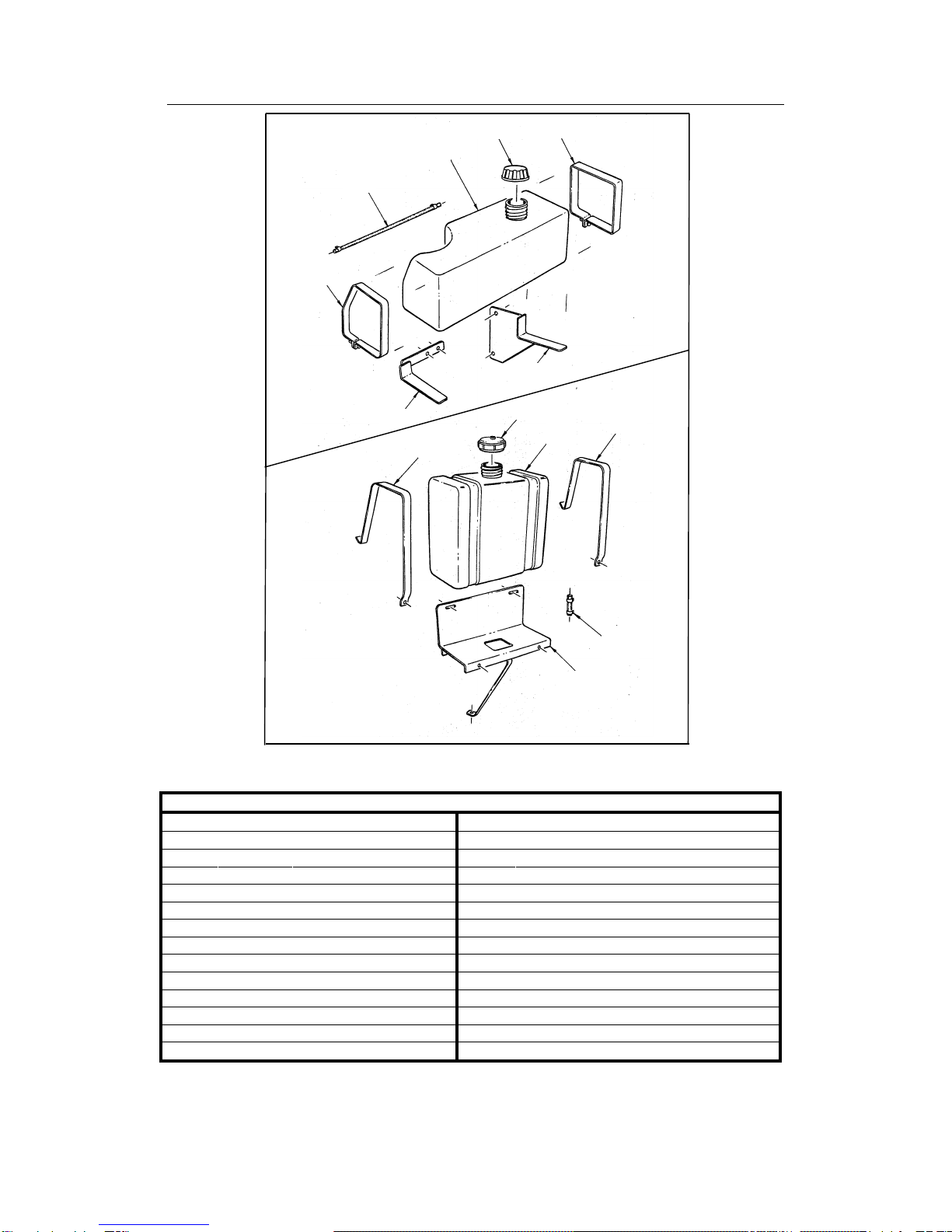
FUEL TANKS / SUNDRY PARTS
ILLUS
PART No
DESCRIPTION
PARTS NOT ILLUSTRATED
1
R260
Tank, 6.5lt
D2720
Paint, Deutscher Green 1lt tin
2
R261
Cap, fuel tank
H641
Decal set
3
R262
Strap, angle
4
R263
Strap, square
5
R264
Bracket, rear
6
R265
Bracket, front
7
R266
Hose & clamps
8
R280
Tank, 6.5lt
9
R281
Cap, fuel tank
10
R282
Strap
11
H283
Bracket, tank
12
R284
Hose & clamps
15
1
2
3
4
5
6
7
8
9
10
10
11
12
BRIGGS & STRATTON
ENGINES
HONDA ENGINES

16 WARRANTY POLICY:
•DEUTSCHER MOWERS PTY. LTD. Will warrant the repair or replacement, free of charge,
any parts of the mower, that are defective in materials or workmanship or both for a period
of: 12 months from the date of purchase.
•This does not cover normal ware abuse or incorrect service procedures as set out in the
owners manual. Parts such as blades, blade bolts, tyres and v-belts, which can be
subjected, to use beyond their normal intended working capacity are also excluded.
•This warranty is void if parts other than genuine have been used or if repairs or
modifications have been made without the manufactures written authority.
•This warranty does not obligate the manufacture, agents or dealers to cover transport costs
incurred in the repair or replacement of any defective part.
•The engine on this mower is covered by the engine manufactures warranty supplied with
the mower. For your nearest engine dealer, Phone: Briggs & Stratton: 1800 650 042
Honda M.P.E.: 1800 809 327
All claims to be referred to Rover Mowers
Limited as warranty agents for the manufacturer.
NATIONAL CUSTOMER SERVICE
ROVER MOWERS LIMITED
CURTIN AVENUE WEST
EAGLE FARM, QLD 4009
PHONE: 07 3213 0233
FAX: 1800 806 659
FOR YOUR RECORD:
Model of Mower:…………………………H660………………………………………………………
Serial Number:………………………………………………………………………………………….
Date of Purchase………………………………………………………………………………………
Mower Purchased From ………………………………………………………………………………
……………………………………………………………………………………………………………
……………………………………………………………………………………………………………
Remember: Proof of purchase is the responsibility of the owner and is necessary prior
to warranty work being under taken. An authorised dealer using genuine spare parts
must carry out repairs or your warranty will be void.
Manufactured in Australia by:
DEUTSCHER MOWERS PTY LTD
711 Creswick Road, Ballarat 3350
Part No. H640 Edition: 2 24/08/18
Table of contents
Other Deutscher Lawn Mower manuals


