Deutscher TH910 Series II User manual
DEUTSCHER
TH910
Series II
Ride-on mower
Owner’s Manual
Part No. T961 Edition 1

SAFETY INSTRUCTIONS
1. Know your controls. Read the operator manual carefully. Learn how to stop the engine quickly in any
emergency.
2. Do not allow children or people unfamiliar with these instructions to use the mower. Do not carry
passengers.
3. Make sure the area to e cut is clear of sticks, stones, ones, wire and de ris. The lades could throw
them.
4. Do not mow whilst people, especially children or pets are in the area.
5. Never mow across a slope unless the mower is designed for this purpose.
6. Exercise extreme caution when on slopes. Reduce speed on slopes and in sharp turns to prevent
overturning or loss of control. Do not start suddenly when going uphill or down hill.
7. Stay alert for holes in the terrain and other hidden hazards.
8. Use care when pulling heavy loads or use heavy equipment.
a. Use only approved draw ar hitch point.
. Limit loads to those you can safely control.
c. Do not turn sharply.
d. Use care when acking up.
9. Watch out for traffic when crossing or operating near roadways.
10. Stop lades rotating efore crossing surfaces other than grass.
11. When lades are engaged never direct discharge of materials towards y ystanders or allow anyone near
the machine while it is in operation.
12. Before leaving the operator's position:
a. Disengage cutter clutch.
. Ensure the parking rake is engaged.
c. Stop the engine and remove the ignition key.
13. Stop the engine and disengage the cutter clutch:
a. Before refuelling.
. Before clearing lockages.
c. After hitting a foreign o ject (inspect the mower for damage and make
repairs efore restarting and operating the equipment).
d. Before checking, cleaning or working on the mower.
e. if the machine starts to vi rate a normally (check immediately).
14. The mower operator should e in good physical and mental condition and not under the influence of any
drug or alcohol, which might impair vision, co-ordination or judgement.
15. Never mow while arefoot or wearing open sandals or thongs, wear long trousers and heavy shoes.
16. It is advisa le to wear suita le eye protection when operating the mower.
17. Mow only in good daylight.
18. Before using the mower always visually inspect to see that the lades, olts and cutter assem ly are not
worn or damaged. Replace worn or damaged lades in sets to preserve alance.
19. Check all nuts, and olts often, always e sure the mower is in a safe working condition.
20. Keep safety devices (guards and switches) in place and in working order.
21. Never use the mower unless all guards provided y the manufacturer are in position.
22. Ensure any spare parts used comply with the original manufacturer's recommendations and specifications.
23 Replace worn and faulty silencers.
24. Keep engine free of grass, leaves or excessive grease. These can e a fire hazard.
25. Refuel outdoors only. Do not smoke while refuelling engine. Never remove the cap of the fuel tank or add
fuel while the engine is running or the engine hot. Remove the fuel cap slowly to relieve any tank pressure.
If petrol is spilled, do not attempt to start the engine ut move machine away from the area of the spill and
avoid creating any source of ignition until petrol vapours have dissipated.
26. Check for fuel leaks while refuelling or using the mower. If a fuel leak is found, do not start or run the
engine until the fuel leak is fixed and spilled fuel wiped away.
27. Do not operate the mower in a confined space where exhaust fumes (car on monoxide) can collect.
28. Always mount the mower on the opposite side to the discharge chute.
29. Start the engine carefully with the cutting clutch disengaged.
30. Store the mower in a well ventilated area away from naked flames.
31. Stop the engine when ever you leave the mower, even for a moment.
32. Do not lend or sell the mower without the Owner's Manual.
2

SPECIFICATIONS
ENGINE
Fitted with either: Briggs & Stratton model 28N707 Diamond Plus series, 15.5 hp.
Honda model GXV390K1, 13 hp.
TRANSMISSION
Hydro-Gear hydrostatic transaxle model 310-0800 IHT commercial qualified.
Speed range, varia le 0 to 10 kph.
CUTTING HEAD
Fa ricated 2.5mm steel cutting deck with twin lade plates and lades,
Cutting width 910mm
Height of cut: 30mm to 90mm with 8 variations.
TYRES:
Front 13-500-6 140 kpa pressure
Rear 18-850-8 70 kpa pressure
CONTROLS:
Throttle – mounted on left hand side of control panel marked with SLOW, FAST and CHOKE positions.
Key Ignition – mounted on right hand side of control panel, marked with ON, OFF and START positions.
Transmission Lever – mounted on the left hand side of the control panel with ON, OFF positions.
Parking Brake – mounted on the left hand side of the mower near the seat.
Cutter Drive Engagement Lever – located centre of mower in front of seat
Height control lever – mounted on the right hand side of cutter deck, 8 positions.
Drive Pedal – located on the right hand side of the control panel, varia le speed in oth forward and
reverse direction and returns to neutral position when your foot is not on the pedal.
GENERAL
Length: 1820mm, width: 990mm, height: 1080mm, weight: 230kg.
PRE-START CHECK
Your Deutscher Ride-on Mower comes to you tested and ready to operate with engine and transaxle filled
with oil.
1: Read all safety instructions and know how to stop engine quickly in any emergency.
2: Know your controls – where they are and there function.
3: Use fresh clean unleaded petrol. Do not mix oil with petrol.
4: Adjust the seat to est suit the operator.
SAFETY INTERLOCK SYSTEM
The safety interlock system has een designed for the operator’s safety and should never e tampered
with.
3

OPERATION
STARTING THE ENGINE:
1: Operator must e seated, as to activate safety switch.
2: Move transmission lever to OFF position.
3: Move cutter engagement lever to the DISENGAGED position.
4: For cold start move throttle lever to CHOKE position, (warm start to FAST position).
5: Turn key to start.
6: When engine starts, move throttle lever to desired engine speed.
TO DRIVE MOWER:
1: Move transmission lever to ON position.
2: Release parking rake.
3: Place foot on drive pedal and apply pressure with all of foot to go forward or heel of foot on the
ack part of pedal for reverse.
The following tips will assist control of the mower and reduce the risk of damage or accidents:
1: Always operate the pedal smoothly when moving off and when coming to a stop.
2: Always keep your foot on the pedal when stopping. Lifting your foot will cause the machine to stop
suddenly and throw you forward or ackwards (depending on the direction you are travelling).
3: Always pause in neutral when changing from forward to reverse or reverse to forward.
CUTTER ENGAGEMENT
1: Move throttle lever to approximately two thirds engine speed.
2: Slowly move cutter drive lever forward to engage cutter clutch.
IMPORTNANT When engaging or releasing cutter drive lever, always operate slowly. Do not use
fast or jerking motion as this will overload the engine causing it to stall.
MAINTENANCE
ENGINE Refer engine manual.
1: To change oil, start and run engine until operating temperature to warm oil.
2: Fit a drain tu e to engine drain fitting.
3: Open the drain fitting two turns only and allow oil to drain completely.
4: Re-tighten the drain fitting and refill engine with oil to correct level as per engine manual.
TRANSAXLE The transaxle fitted to the mower normally will not require servicing during the life of the mower.
Should the transaxle require attention, it should only e carried out y technically qualified person.
It is important that you keep the unit clean from grass clippings, oil, and dirt etc. Avoid high
pressure cleaning. If cooling fan is roken or damaged, it should e replaced immediately.
BLADES: It is important that you visually inspect the lades, lade olts and nuts to ensure that they are in a
safe operating condition. Replace all components in sets to retain alance of lade plate.
TO CHANGE BLADES
1: Ensure ignition switch is in the OFF position.
2: Un-screw off set nut and remove curved washer.
3: Blade and olt are removed from underneath
lade plate.
4: Inspect parts for wear or damage and replace.
5: Replace y reversing the a ove procedure, make sure
the lade is fitted underneath the lade plate. Screw on off set nut
until nut is level with the top of the olt, and ensure that the offset of the
nut is facing out.
4
OFF SET NUT
CURVED WASHER
BLADE
BLADE PLATE
BOLT
ROTATION
Fig.1
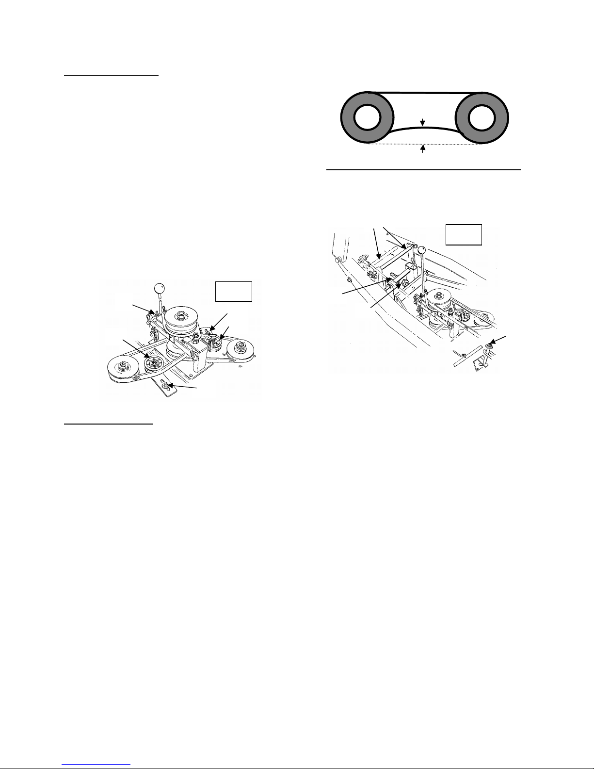
BELT ADJUSTMENTS:
CENTRE SPINDLE BELT Fig.2
1: Place height lever in mid position.
2: Loosen nut “A” and tighten nut “B” (Fig.2)
TRANSAXLE BELT:
1: Loosen the four engine mount olts. WARNING! DO NOT OVER TIGHTEN BELTS.
2: Slide engine forward along slots.
3: Re-tighten the engine mount olts.
4: Adjust centre spindle elt as a ove.
CUTTER SPINDLE BELTS: (Fig.3)
1: Loosen nut “C”.
2: Push jockey pulley ”D” against elt until tight.
3: Tighten nut “C”.
REPLACING BELTS
CENTRE SPINDLE BELT Fig.2
1: Uncouple seat switch wire (Bullet connector at rear of seat).
2: Remove seat panel.
3: Set cutting deck in mid cutting height position.
4: Remove elt guide at rear of pulley.
5: Loosen Nut "B" so that main elt is loose.
6: Loosen all engine mounting olts.
7: Push engine to rear of mower and remove transmission elt.
8: Remove elt from pulleys and replace.
9: Fit transmission elt.
10: Loosen nut "A" till main drive elt is tensioned and tighten nut "B".
11: Tighten engine olts and replace elt guide.
TRANSMISSION BELT Fig.2
1: Uncouple seat switch wire ( ullet connector at rear of seat)
2: Remove seat panel
3: Remove fan cover from rear of engine
4: Loosen nut "B" so that main elt is lose
5: Loosen all engine mounting olts and pushing engine ack on slots
6: Remove elt off engine pulley first then transmission pulley.
7: Fit new elt over transmission pulley then onto engine pulley.
8: Loosen nut "A" till centre elt is tensioned (it will also tension transmission elt) and tighten nut "B".
9: Tighten all engine mounting olts and refit panels.
5
20mm
A
B
Fig.2
Fig.3
C
D
C
D
E
E
C D

CUTTER SPINDLE BELTS Fig.3
1: Uncouple seat switch wire ( ullet connector at rear of seat)
2: Remove seat panel
3: Remove elt guide from rear of pulley
4: Loosen nut "B" and remove main drive elt
5: Remove covers over cutter spindles
6: Position clutch laver in engaged position
7: Remove four "R" clips
8: Remove clutch ars
9: Loosen nuts on rake and turn plate sideway ⅛ turn to allow clearance for elts to slip through.
(Do not loosen ⅝ nuts)
10: Replace elts and reassem le.
CLUTCH ADJUSTMENT Fig.3
1: Loosen nut ”E”.
2: Tighten nut underneath square lock (1/2 turn should e sufficient).
DO NOT OVER ADJUST, clutch should have .75mm gap etween clutch lining and pulley surface
when in rake position.
3: Ensure nut “E” tight when adjusted.
LUBRICATION CHART
Engine As per engine manual
Grease king pins 20 hours
Grease front axle pivot, fig.4 20 hours
Grease vertical gear steering gear shaft, fig.4 20 hours
Grease cutter spindles & clutch spindle, fig.5 20 hours
Oil steering wheel shaft (top & ottom), fig. 4 20 hours (oil)
Grease steering gears, fig.4 20 hours (smear with grease)
Oil all moving parts 20 hours
6
GREASE
Fig.4
OIL
GREASE
Fig.5

REPLACING BEARINGS IN CUTTER SPINDLES
1: Remove pulley guard.
2: Remove lock nuts from on top of pulleys
3: Remove pulley and washer
4: Spindle and flange will push out under cutter deck.
5: Remove earings and spacer sleeve and clean all parts.
6: Press ottom earing into housing
7: Fit spindle and flange to ottom earing in housing.
8: Insert spacer sleeve
9: Wipe clean top earing and area which locates earing with an oil solvent.
10: Apply "Loctite" to top earing and housing and press firmly into housing.
11: Fit top spacer washer and pulley and tighten assem ly together with lock nuts.
Do not grease until "Loctite" is cured. (12 Hours)
REPLACING BEARINGS FOR CENTRE SPINDLE BEARINGS:
1: Remove seat panel and cutting deck from mower,
2: Undo top nut on top of spindle and remove stepped ushes and top pulley,
3: Remove clutch ars y removing R-clips,
4: Undo nuts on rake plate and turn 90 degrees and push down clutch assem ly down to expose
clutch gear,
5: Remove clutch gear and key in shaft and remove rake assem ly,
6: Remove dust cap from ottom of housing and undo nut on spindle,
7: Remove spindle from housing and press out earing outer rings,
8: Clean all parts in replace any defective parts,
9: Press earing outer rings into each end of spindle housing.
10: Fit earing, seal washer, dou le pulley, and 2 nuts to spindle and tighten,
11: Place spindle into housing,
12: Place ottom earing over spindle and screw on special nut using ”Loctite”.
13: Adjust earing, and lock y forcing nut rim into keyway with centre punch,
14: Press dust cap on to ase of spindle housing securing with "Loctite", and grease earings.
15: Fit rake assem ly over spindle, then fit key, clutch gear and clutch ars,
16: Move rake into rake position,
17: Place stepped ushes each side of pulley, fit pulley to spindle and tighten nut,
18: Fit cutter elt and guide.
REMOVE CUTTER DECK Fig.2
1: Turn ignition key off and remove.
2: Place transmission lever In “OFF” position.
3: Uncouple seat switch ( lade connector at rear of seat) and remove seat panel.
4: Raise cutter deck to highest position.
5: Uncouple the two wires from safety switch.
6: Remove rod “C”.
7: Remove rod “D”
8: Remove rear locating nut “E” and washer.
9: Remove elt from pulley.
10: Lift chassis clear of deck and wheel mower ackwards.
NOTE Blades can e changed with out removing cutting deck. R.H. lades are accessi le through the
side chute. L.H. lades can e replaced y elevating the front of the mower 300mm.
7

WHEN ORDERING PARTS
SPECIFY THE MODEL AND SERIAL NUMBER
ON THE NAME PLATE OF THE MOWER
AND THE PART NUMBER IN THIS MANUAL
PART No DESCRIPTION
T914 Decal set
T920 Paint, 150g pressure can, Hawthorn Green
T201 Oil drain valve, B&S
T202 Oil drain valve, Honda
THE MANUFACTURERS RESERVE THE RIGHT TO ALTER, CHANGE OR VARY THE
SPECIFICATIONS OF THE MACHINE OR ANY OF THE COMPONENT PARTS
AT ANY TIME WITH OUT NOTICE
8
ILLUS.
PART No
DESCRIPTION
ILLUS.
PART No
DESCRIPTION
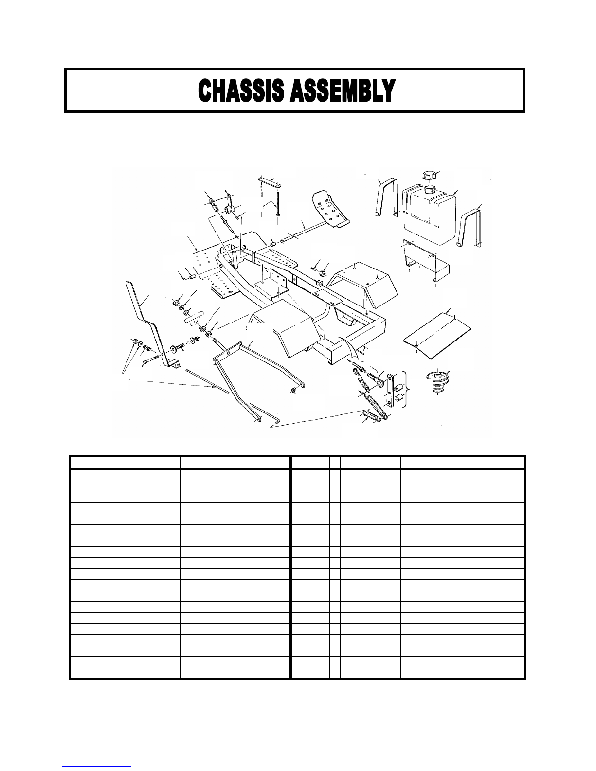
1 T720 Chassis
18 T510 Nut, adjustment 5/8”w x 2
2 T567 Ball joint, 3/8”
19 HD124 Spring washer
3 T721 Pivot arm
20 T527 Washer
4 T722 Speed rod & all ends
21 T435 Swivel link
5 T723 Battery strap
22 T508 Pivot ush
6 T724 Bolt, attery strap x 2
23 T729 A-frame
7 T581 Pedal
24 T511 Flanged ush x 2
8 T725 Bush x 2
25 T730 Spring x 2
9 T726 Washer
26 Y03 Spring
10 H08 Pin x 2
27 T731 Pivot assem ly
11 H07 Roller, nylon x 2
28 R87 Spring
12 R282 Tank strap x 2
29 T732 Pivot olt & nut
13 R281 Cap, fuel tank
30 T733 Lever, park rake
14 R280 Fuel tank, 6lt
31 T734 Rod, park rake
15 T727 Tank racket
32 T735 Roll pin
16 T728 Fan cover
17 T200 Engine pulley
9
1
2 3
5
7
32
1
2
1
14
12
10
15
8
8
31
29
28
16
17
4
25
26
24
23
27
18
19
20 21 22
18
30
11
2
9
2
4
2
4
ILLUS.
PART No
DESCRIPTION
ILLUS.
PART No
DESCRIPTION
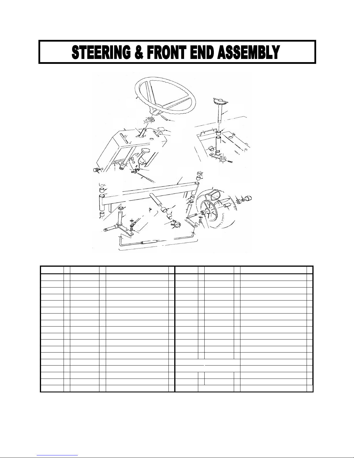
1 T550 Steering wheel
17 R93 Thrust washer x 2
2 T552 Top earing
18 MR90 King pin & stu axle L.H.
3 T554 Roll pin
19 MR95 King pin & stu axle R.H.
4 T551 Steering column & gear
20 T568 Front tie rod & ends
5 T557 T-kno x 2
21 T567 Ball ends 3/8”unf x 2
6 T574 Lever assem ly x 2
22 T524 Grease nipple 45o
7 T558 Ca le, universal x 2
23 R87 Spring x 2
8 T560 Panel
24 T570 Rear tie rod assem ly
9 T561 Hinge pin x 2
25 T562 Wheel assem ly
10 T553 Bottom earing
-- T563 Tyre 13-500-6
11 T513 Steering spindle & gear
-- T564 Tu e 13-500-6
12 R100 Cap x 2
26 T588 Bearing, 6203 x 2
13 T528 Drag link & set screw
27 RD174 Nut 5/8”unf x 2
14 R92 Collar x 3
28 H514 Spacer, earing
15 R91 Bush x 8
16 T566 Axle eam
10
1
3
5
6
8
11
15
15
13
14
15
25
5
6
7
10
14
15
9
16
26 27 12
15
17
19
17
18 21
20
22
14
24
23 26
2
15
28

ILLUS.
PART No
DESCRIPTION
ILLUS.
PART No
DESCRIPTION
1 T150 Hydro-gear IHT310-0800
11 T108 Wheel nut x 8
2 T161 Hose, reather
12 T155 V- elt, A32
3 70110 Fitting, hose #
13 T112 Wheel assy. turf
4 70109 Cap, vent assem ly #
-- T113 Rim
5 Y03 Spring
-- T114 Tyre, turf, 18-850-8
6 T164 Neutral racket assem ly
-- T115 Tu e, 18-850-8
7 T154 Key 3/16”
-- T136 Wheel assy. Kno y
8 T558 Ca le, universal
-- T137 Tyre, Kno y, 18-950-8
9 T152 Hu & set screw
10 T153 Cirlip x 2
NOTE Parts marked # are to be sourced from an Authorised Briggs & Stratton Dealer
11
1
2
3
4
12
13
11
10
9
7
8
5
6
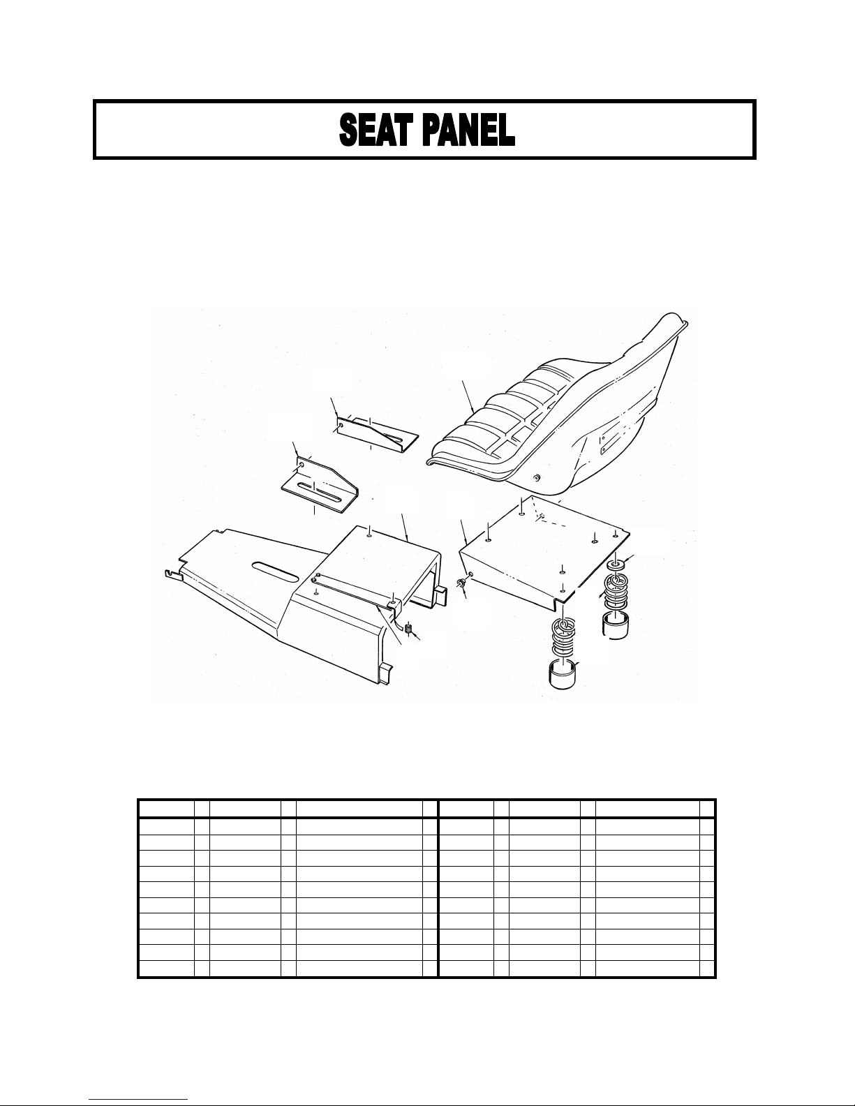
ILLUS.
PART No
DESCRIPTION
ILLUS.
PART No
DESCRIPTION
1 T530 Seat
8 DD111 Washer
- T541 Back rest, optional
9 T535 Spring
2 T534 Hinge racket R.H.
10 T536 Spring cap
3 T533 Hinge racket L..H.
11 T714 Bush x 2
4 T711 Seat ase
5 T712 Seat panel
6 D134 Spring
7 T713 Strap, earth
12
1
2
3
5 4
8
11
6
7
9
10

ILLUS.
PART No
DESCRIPTION
ILLUS.
PART No
DESCRIPTION
1 T433 Pin 5/8”
8 T434 Link pin
2 T442 Link racket
9 T435 Swivel link
3 T741 Washer
10 T441 Collar 5/8”
4 T633 R-clip
11 T742 Su frame & deflector
5 T440 Crank arm
12 T431 Deflector
6 T439 Rod, connecting
7 D50 Spring
13
10
4
1
2
9
3
5
8
11
12
7
6
4
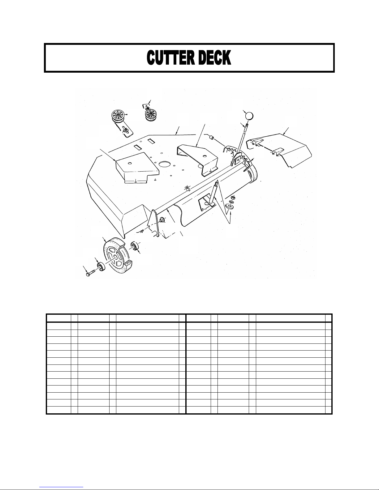
ILLUS.
PART No
DESCRIPTION
ILLUS.
PART No
DESCRIPTION
1 T700 Cutter deck
12 T705 Pivot olt
2 T401 Side chute
13 Y555 Wheel assem ly
3 Y13 Kno
-- Y557 Tyre
4 T701 Lever, raise & lower
-- Y556 Rim assem ly
5 T402 Pulley guard L..H.
14 T588 Bearing 6202 x 2
6 T403 Pulley Guard R.H.
15 Y558 Bolt & washer
7 T415 Height rack
16 T640 Bracket L.H. pulley, high
8 T702 Spring
17 T641 Bracket R.H. pulley, low
9 T411 Rear mount assem ly
18 T618 Pulley x 2
10 T703 Cross ar
11 T704 Pivot ush, threaded
14
1
17
18
16
5
6
3
4 2
8
7
9
10
11
12
13
14
14
15
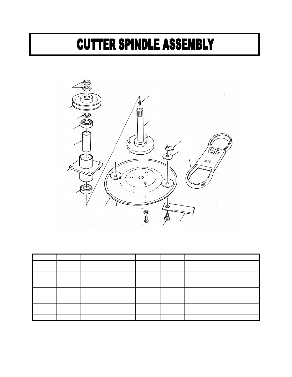
ILLUS.
PART No
DESCRIPTION
ILLUS.
PART No
DESCRIPTION
1 G30 Lock nut x 2
10 G36 Bolt & spring washer x 6
2 T454 Pulley x 2
11 D02 Bolt, lade x 4
3 T452 Washer x 2
12 R01 Blade x 4
4 R28 Bearing, 6205 x 4
13 D04 Washer, lade x 4
5 T451 Sleave x 2
14 D03 Nut, lade x 4
6 T453 Housing x 2
15 T432 V- elt, B32 Dayco super 2 x 2
7 R13 Grease nipple x 2
8 T450 Spindle & flange x 2
9 R32 Blade plate x 2
15
1
2
3
4
5
6
4
7
8
14
13
15
9 10
11
12

ILLUS.
PART No
DESCRIPTION
ILLUS.
PART No
DESCRIPTION
1 Y13 Kno
18 T622 Cap, ottom housing
2 T654 Lever, engagement
19 T629 Pin
3 T623 Eye olt adjuster
20 T608 Nut
4 T624 Pivot Bolt
21 T604 Circlip, 52mm int
5 T610 Clutch drive gear
22 T602 Stepped ush x 2
6 G30 Lock nut x 2
23 T603 Bearing,6205
7 T600 Dou le pulley
24 T651 Clutch pulley & lining
8 T636 Seal washer
25 T652 Clutch plate
9 G33 Bearing x 2
26 RD105 Circlip 30mm ext
10 T655 Woodruff key
27 T653 Brake plate & lining
11 T638 Spindle & ottom lock nut
28 T612 Circlip, 62mm int
11a T639 Lock nut
29 T614 Bearing 6206
12 T628 Stud, adjustment x 2
30 T613 Bearing holder
13 T627 Side strap R.H.
31 T634 Belt guide
14 T626 Side strap L.H.
32 T657 Complete assem ly
15 T633 R-clip x 4
-- T309 Safety switch
16 T630 Spring x 2
-- Y41 V- elt, engine-spindle B59
17 T656 Main housing
-- R13 Grease nipple
16
1
2
3
4
6
8
9
10
1
1
12
1
12
12
17
16
31
19
15 16
14
11a
18
30
29
28
27
26
25
24
21
22
23
22
15
20
5
7
9

ILLUS.
PART No
DESCRIPTION
ILLUS.
PART No
DESCRIPTION
1 T303 Starter ca le 560mm (B&S)
7 T309 Safety switch
2 T304 Battery ca le 460mm
8 T305 Wire loom (B&S)
3 R323 Battery ca le 330mm (Honda)
-- T306 Wire loom (Honda)
4 R313 Battery Ca le 230mm (B&S)
9 T311 Connecter, insulator
5 T302 Solenoid (B&S)
6 T316 Key switch
17
1
2
3
4
5
6
9
7
8
14
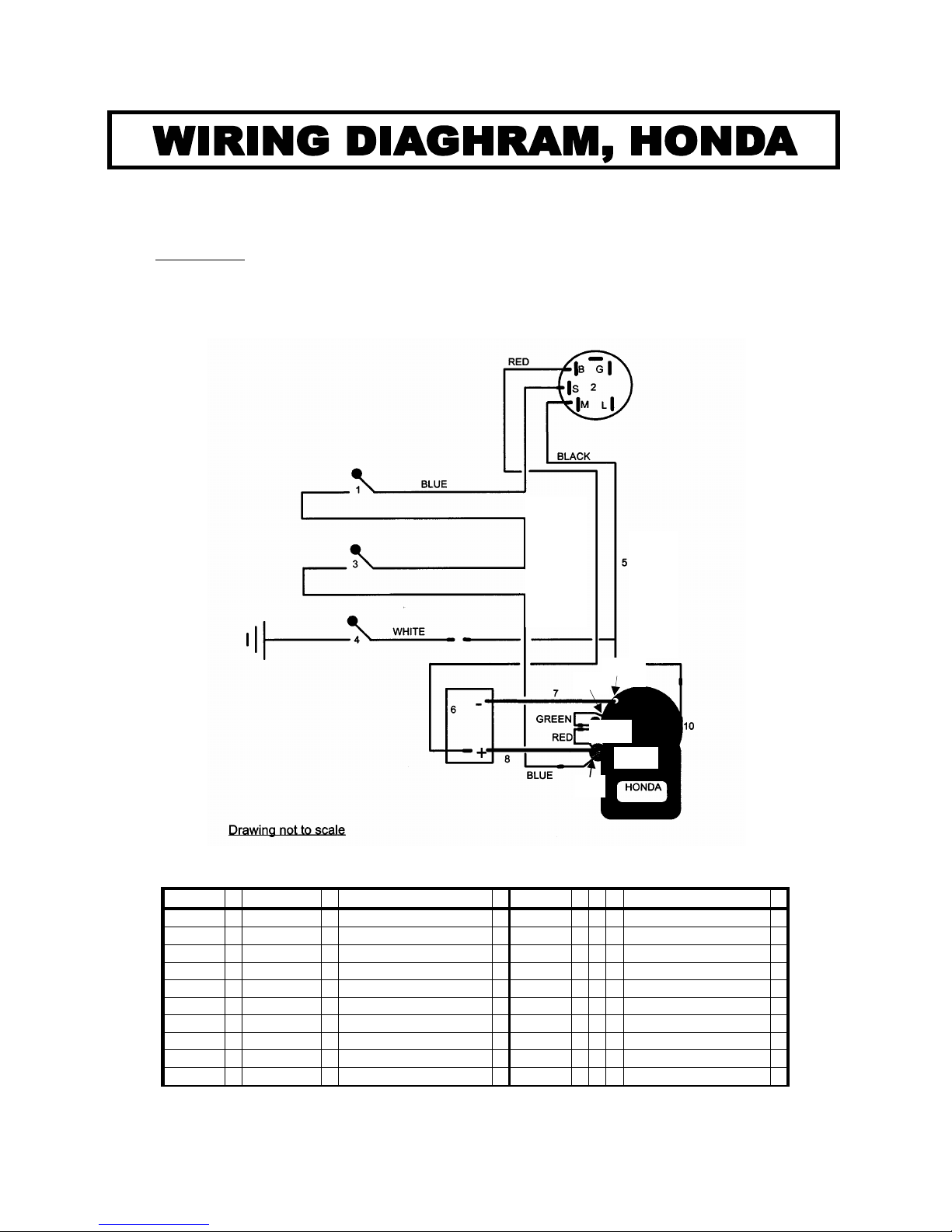
For use on DEUTSCHER TH910 Series II Ride-on mower with Honda GXV90K1 DAEU engines.
WARNING: Incorrect wiring may result in damage to the engines electrical system.
Only qualified and or competent electrical technicians should attempt
any repairs or alterations.
ILLUS.
PART No
DESCRIPTION
ILLUS.
DESCRIPTION
1 T309 Safety switch, trans.
9 Starter motor
2 T316 Key switch
10 Stop switch
3 T309 Safety switch, cutters
11 Engine
4 T311 Insulator, seat
12 Earth, engine mount
5 T306 Wiring loom
13 Regulator / rectifier
6 T315 Battery 12 volt, 606
14 Earth, reg/rectifier
7 T304 Ca le, 460mm
8 R323 Ca le, 330mm
18
1
13
16
11
14
13
9
12
14
14
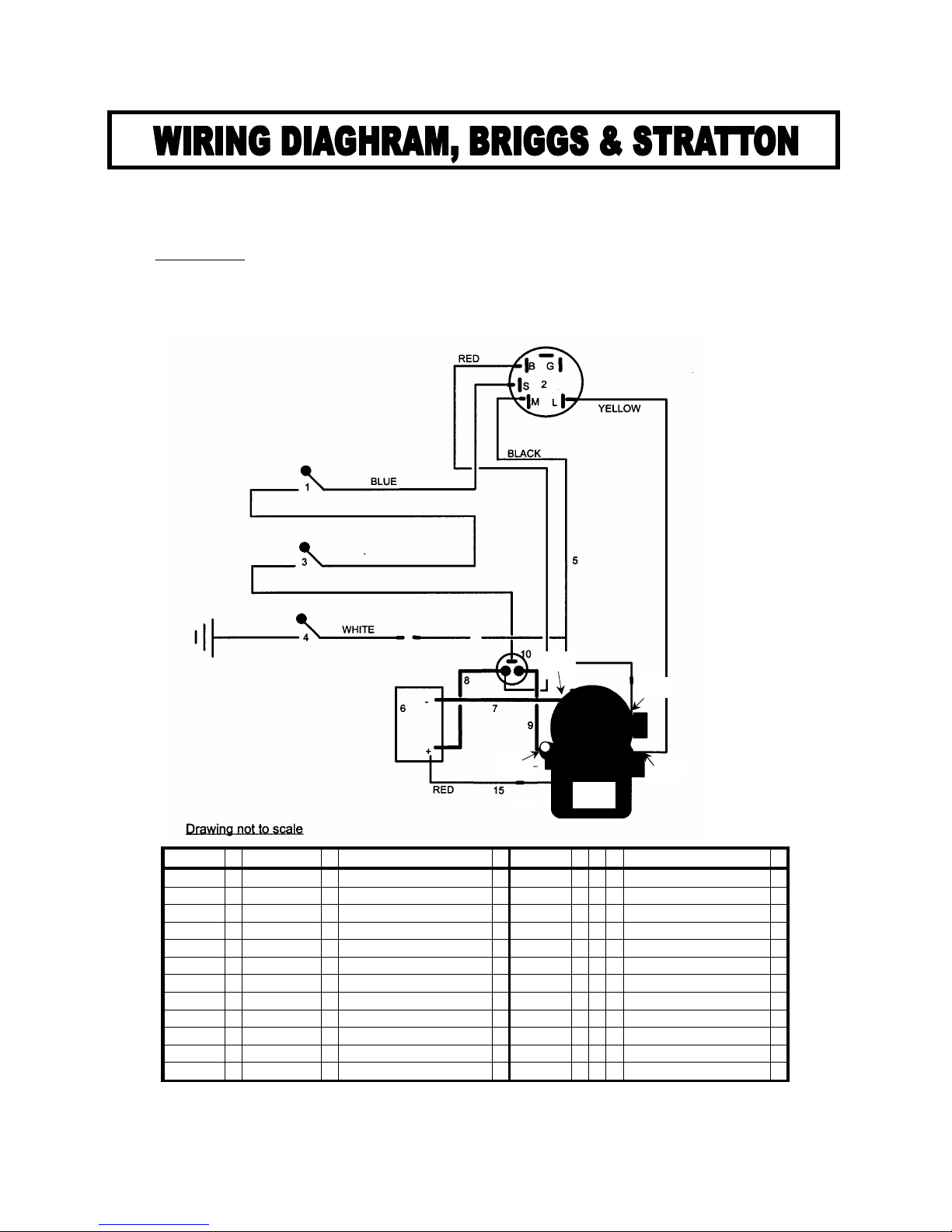
For use on DEUTSCHER TH910 Series II Ride-on mower with Briggs & Stratton engine 28N707 series.
WARNING: Incorrect wiring may result in damage to the engines electrical system.
Only qualified and or competent electrical technicians should attempt
any repairs or alterations.
ILLUS.
PART No
DESCRIPTION
ILLUS.
DESCRIPTION
1 T309 Safety switch, trans.
11 Starter motor
2 T316 Key switch
12 Car y. solenoid
3 T309 Safety switch, cutters
13 Stop switch
4 T311 Insulator, seat
14 Engine
5 T305 Wiring loom
15 Charge wire
6 T315 Battery 12 volt, 606
16 Engine mount, earth
7 T304 Ca le, 460mm
8 R313 Ca le, 230mm
9 T303 Ca le, 560mm
10 T302 Solenoid
19
1
13
16
11

WARRANTY POLICY MOWER
H. F. DEUTSCHER PTY. LTD. Will warrant the repair or replacement, free of charge, any parts of the mower that
are defective in materials or workmanship or oth for a period of:
12 MONTHS FROM DATE OF PURCHASE.
• This does not cover normal wear a use or incorrect service procedures as set out in the owner’s manual.
Parts such as lades, lade olts, tyres and v- elts, which can e su jected, to use eyond their normal
intended working capacity are also excluded.
• This warranty is void if parts other than genuine have een used or if repairs or modifications have een
made without the manufacturer’s written authority.
• This warranty does not o ligate the manufacturer’s agent or dealers to cover transport costs incurred in the
repair or replacement of any defective part.
The engine and transaxle on this mower are covered y separate manufacturer’s warranty
For your nearest Briggs & Stratton and Hydro-Gear dealer, Phone: 03 9796 4900
For your nearest Honda Power Equipment dealer, Phone: 03 9270 1111
All claims to be referred to ROVER MOWERS LIMITED
as warranty agents for the manufacturer.
NATIONAL CUSTOMER SERVICE
ROVER MOWERS LIMITED
155 FISON AVENUE WEST
EAGLE FARM, QLD. 4009
Phone 07 3213 0233
Fax 1800 806 659
www.rovermowers.com.au
FOR YOUR RECORD
Model of Mower:………………………TH910………………………………………………………
Serial Num er:………………………………………………………………………………………….
Date of Purchase………………………………………………………………………………………
Mower Purchased From ………………………………………………………………………………
……………………………………………………………………………………………………………
Remember Proof of purchase is the responsibility of the owner and is necessary prior to warranty work
being under taken. An authorised dealer using genuine spare parts must carry out repairs or your warranty
will be void.
Manufactured in Australia y:
H.F. DEUTSCHER PTY LTD
711 Creswick Road, Ballarat 3350
Part No. T961 Edition: 2 24/09/06
Table of contents
Other Deutscher Lawn Mower manuals


