DEUTSCHMANN AUTOMATION LOCON 24 User manual
Instruction manual
Electronic cam control
LOCON 24, 48, 64, LTC
Display- and operating unit
TERM 24 and TERM 6
Deutschmann Automation GmbH & Co. KG
Carl-Zeiss-Str. 8 D-65520 Bad Camberg +49-(0)6434 / 9433-0 +49-(0)6434 / 9433-40
eMail: mail@deutschmann.de Internet: http://www.deutschmann.com


29.10.13 Instruction manual LOCON 24, 48, 64, LTC, TERM 24 and TERM 6 V. 8.8 3
Deutschmann Automation GmbH & Co. KG
Foreword
This operating manual provides users and OEM customers with all the information necessary for
the installation and operation of the product described in this manual.
All details contained in this manual have been checked carefully, however, they do not represent
an assurance of product characteristics. No liability can be accepted for errors. DEUTSCHMANN
AUTOMATION reserves the right to carry out alterations to the described products in order to
improve the reliability, function or design thereof. DEUTSCHMANN AUTOMATION only accepts
liability to the extent as described in the terms and conditions of sale and delivery.
All rights reserved, including translation. No part of this manual may be reproduced or pro-
cessed, copied or distributed in any form whatsoever (print, copy, microfilm or any other process)
without written permission from DEUTSCHMANN AUTOMATION.
Bad Camberg, October 2013
Version 8.8 dated 29.10.13 Art.-No. V2981E
P/C: A
Copyright by DEUTSCHMANN AUTOMATION, D-65520 Bad Camberg 1994-2013

Deutschmann Automation GmbH & Co. KG
4 Instruction manual LOCON 24, 48, 64, LTC, TERM 24 and TERM 6 V. 8.8 29.10.13

24.7.12 Instruction manual LOCON 24, 48, 64, LTC, TERM 24 and TERM 6 V. 8.8 5
Deutschmann Automation GmbH & Co. KG
1Introduction . . . . . . . . . . . . . . . . . . . . . . . . . . . . . . . .11
1.1 On this manual . . . . . . . . . . . . . . . . . . . . . . . . . . . . . . 11
1.1.1 Symbols . . . . . . . . . . . . . . . . . . . . . . . . . . . . . . . . . . . . 11
1.1.2 Concepts . . . . . . . . . . . . . . . . . . . . . . . . . . . . . . . . . . . 11
1.1.3 Suggestions . . . . . . . . . . . . . . . . . . . . . . . . . . . . . . . . . . 11
1.2 From the mechanical system to an electronic system . . . . . . . . . . 12
1.3 Deutschmann Automation’s range of products . . . . . . . . . . . . . . 12
2EMC Directives for products of DEUTSCHMANN AUTOMATION . . 13
3Electrical connections LOCON 24, 48, 64 . . . . . . . . . . . . . . . 14
3.1 Rear view LOCON 24, 48, 64 . . . . . . . . . . . . . . . . . . . . . . . 14
3.2 Pin assignment LOCON 24, 48, 64 . . . . . . . . . . . . . . . . . . . . 15
3.2.1 Pin assignment X1 (2x24-pin screw terminals) . . . . . . . . . . . . . . . . 15
3.2.2 Pin assignment X2 (1x16-pin screw terminals) . . . . . . . . . . . . . . . . 15
3.2.3 Pin assignment X2 (1x16-pin screw terminals) . . . . . . . . . . . . . . . . 16
3.2.4 Pin assignment X3 (1x6-pin screw terminals) . . . . . . . . . . . . . . . . . 16
3.2.5 Pin assignment X4 (1x24-pin screw terminals) . . . . . . . . . . . . . . . . 16
3.2.6 Pin assignment X5 (1x7-pin screw terminals) . . . . . . . . . . . . . . . . . 16
3.2.7 Pin assignment X6 (1x3-pin screw terminal) . . . . . . . . . . . . . . . . . 16
3.2.8 Pin assignment X7 . . . . . . . . . . . . . . . . . . . . . . . . . . . . . . 17
3.2.8.1 Pin assignment X7 - Standard version (9-pin D-Sub female connector). . . . . . . 17
3.2.8.2 Pin assignment X7 at the Profibus-version . . . . . . . . . . . . . . . . . . . . . 17
3.2.8.3 Pin assignment X7 at the MPI-version. . . . . . . . . . . . . . . . . . . . . . . . 17
3.3 Signal description LOCON 24, 48, 64 . . . . . . . . . . . . . . . . . . . 18
3.3.1 Status LEDs . . . . . . . . . . . . . . . . . . . . . . . . . . . . . . . . . . 19
3.3.1.1 Front view . . . . . . . . . . . . . . . . . . . . . . . . . . . . . . . . . . . . . . 19
3.3.1.2 Rear view . . . . . . . . . . . . . . . . . . . . . . . . . . . . . . . . . . . . . . 19
3.4 External program selection . . . . . . . . . . . . . . . . . . . . . . . . 19
3.4.1 Applying the corresponding voltages . . . . . . . . . . . . . . . . . . . . . 19
3.4.2 Generation of the acceptance edge . . . . . . . . . . . . . . . . . . . . . . 20
3.4.3 Graphic representation of program selection . . . . . . . . . . . . . . . . . 20
3.5 Installation and commissioning of LOCON 24, 48 and 64 . . . . . . . . 20
3.5.1 Connection of the supply voltage . . . . . . . . . . . . . . . . . . . . . . . 20
3.5.2 Connection of the equipotential bonding system . . . . . . . . . . . . . . . 21
3.5.3 Connection of the inputs and outputs . . . . . . . . . . . . . . . . . . . . . 21
3.5.4 Connection of the serial RS232 interface . . . . . . . . . . . . . . . . . . . 22
3.5.4.1 Interface-switch . . . . . . . . . . . . . . . . . . . . . . . . . . . . . . . . . . . 22
3.5.5 Connection of the DICNET bus interface . . . . . . . . . . . . . . . . . . . 22
3.5.6 Connection of the floating fault alarm contact . . . . . . . . . . . . . . . . . 22
4Basic unit TERM 24, LOCON 24, 48 and 64 . . . . . . . . . . . . . . 23
4.1 Front view . . . . . . . . . . . . . . . . . . . . . . . . . . . . . . . . . 23
4.1.1 Version IP 54 . . . . . . . . . . . . . . . . . . . . . . . . . . . . . . . . . 23
4.1.2 Version IP 65 . . . . . . . . . . . . . . . . . . . . . . . . . . . . . . . . . 23

Deutschmann Automation GmbH & Co. KG
6 Instruction manual LOCON 24, 48, 64, LTC, TERM 24 and TERM 6 V. 8.8 24.7.12
5Mechanical installation instructions TERM 24, LOCON 24, 48, 64 . . 24
5.1 Version IP 54 . . . . . . . . . . . . . . . . . . . . . . . . . . . . . . . 24
5.2 Version IP 65 . . . . . . . . . . . . . . . . . . . . . . . . . . . . . . . 24
5.3 PM-version . . . . . . . . . . . . . . . . . . . . . . . . . . . . . . . . 24
5.4 Dimensional drawings . . . . . . . . . . . . . . . . . . . . . . . . . . . 25
5.4.1 LOCON 24-IP54 . . . . . . . . . . . . . . . . . . . . . . . . . . . . . . . .25
5.4.2 LOCON 24-IP65 . . . . . . . . . . . . . . . . . . . . . . . . . . . . . . . .26
5.4.3 LOCON 24PM . . . . . . . . . . . . . . . . . . . . . . . . . . . . . . . . .27
5.4.4 TERM 24-IP54 . . . . . . . . . . . . . . . . . . . . . . . . . . . . . . . . .28
5.4.5 TERM 24-IP65 . . . . . . . . . . . . . . . . . . . . . . . . . . . . . . . . .28
6Electrical connections TERM 24 . . . . . . . . . . . . . . . . . . . . 29
6.1 Pin assignment X1 TERM 24 (5-pin screw-type plug connector) . . . . . 29
6.2 Installation and commissioning of the TERM 24 . . . . . . . . . . . . . 29
6.2.1 Connection of the supply voltage . . . . . . . . . . . . . . . . . . . . . . .29
6.2.2 Connection of the serial RS232 interface (optional) . . . . . . . . . . . . . .29
6.2.3 Connection of the DICNET bus interface . . . . . . . . . . . . . . . . . . .29
7LOCON 24, 48 and 64 options . . . . . . . . . . . . . . . . . . . . . . 30
7.1 Expansion to 32 outputs (LOCON 24 only) . . . . . . . . . . . . . . . . 30
7.2 Inputs and logic functions (LOCON 24 and 48 only) . . . . . . . . . . . 30
7.3 SSI interface . . . . . . . . . . . . . . . . . . . . . . . . . . . . . . . 30
7.4 Incremental encoder; incremental counting/direction inputs . . . . . . . 30
7.5 Encoder monitoring (option G) . . . . . . . . . . . . . . . . . . . . . . 30
7.6 Speed display . . . . . . . . . . . . . . . . . . . . . . . . . . . . . . . 31
7.7 Direction-cams . . . . . . . . . . . . . . . . . . . . . . . . . . . . . . 31
7.8 Angle-time cam . . . . . . . . . . . . . . . . . . . . . . . . . . . . . . 32
7.9 Memory expansion . . . . . . . . . . . . . . . . . . . . . . . . . . . . 32
7.10 Offline programming . . . . . . . . . . . . . . . . . . . . . . . . . . . 32
7.11 Data backup and documentation on PC . . . . . . . . . . . . . . . . . 33
7.12 Lockable outputs . . . . . . . . . . . . . . . . . . . . . . . . . . . . . 33
7.13 Program controller function (encoder simulation) . . . . . . . . . . . . . 33
7.14 Analog outputs . . . . . . . . . . . . . . . . . . . . . . . . . . . . . . 33
7.15 Option X37 - encoder monitoring . . . . . . . . . . . . . . . . . . . . . 34
7.16 Option H08 - highspeed-idle time compensation . . . . . . . . . . . . . 34
7.17 Option X53 (preset value) . . . . . . . . . . . . . . . . . . . . . . . . . 34
7.18 Option X55 (locked outputs) . . . . . . . . . . . . . . . . . . . . . . . 34
7.19 Option X59 (braking angle display) . . . . . . . . . . . . . . . . . . . . 35
7.20 Option X81 (24 Bit SSI-encoder) . . . . . . . . . . . . . . . . . . . . . 35
7.21 Special versions . . . . . . . . . . . . . . . . . . . . . . . . . . . . . . 35
8LOCON LTC (special version) . . . . . . . . . . . . . . . . . . . . . . 36
8.1 Mechanics space requirements . . . . . . . . . . . . . . . . . . . . . . 36
8.2 Electrical connections . . . . . . . . . . . . . . . . . . . . . . . . . . . 37

24.7.12 Instruction manual LOCON 24, 48, 64, LTC, TERM 24 and TERM 6 V. 8.8 7
Deutschmann Automation GmbH & Co. KG
8.2.1 Rear view: Terminal allocation . . . . . . . . . . . . . . . . . . . . . . . . 37
8.2.2 Terminal allocation . . . . . . . . . . . . . . . . . . . . . . . . . . . . . . 38
8.2.3 Example for the wiring scheme . . . . . . . . . . . . . . . . . . . . . . . . 39
8.3 Programming of the cams . . . . . . . . . . . . . . . . . . . . . . . . . 40
8.4 Function "Apprentissage" . . . . . . . . . . . . . . . . . . . . . . . . . 41
8.4.1 Presentation . . . . . . . . . . . . . . . . . . . . . . . . . . . . . . . . . . 41
8.4.2 Starting the function "Apprentissage" . . . . . . . . . . . . . . . . . . . . . 41
8.5 Control . . . . . . . . . . . . . . . . . . . . . . . . . . . . . . . . . . 42
8.5.1 Control possibilities . . . . . . . . . . . . . . . . . . . . . . . . . . . . . . 42
8.5.2 Control type 1 . . . . . . . . . . . . . . . . . . . . . . . . . . . . . . . . . 43
8.5.3 Control type 2 . . . . . . . . . . . . . . . . . . . . . . . . . . . . . . . . . 43
8.5.4 Correspondence table . . . . . . . . . . . . . . . . . . . . . . . . . . . . . 44
8.5.5 Description of the control error . . . . . . . . . . . . . . . . . . . . . . . . 44
9Networking terminals with cam controls and PCs . . . . . . . . . . 47
9.1 RS232 link . . . . . . . . . . . . . . . . . . . . . . . . . . . . . . . . . 47
9.2 RS485 link (DICNET) . . . . . . . . . . . . . . . . . . . . . . . . . . . 47
9.3 Cable type for DICNET® . . . . . . . . . . . . . . . . . . . . . . . . . 47
9.3.1 Earthing, shielding . . . . . . . . . . . . . . . . . . . . . . . . . . . . . . 48
9.3.2 Line termination at DICNET® . . . . . . . . . . . . . . . . . . . . . . . . . 48
9.4 Comparison DICNET® - RS232 . . . . . . . . . . . . . . . . . . . . . 48
9.5 Connection examples . . . . . . . . . . . . . . . . . . . . . . . . . . . 49
9.5.1 DICNET link LOCON-TERM . . . . . . . . . . . . . . . . . . . . . . . . . 49
9.5.2 RS232 link LOCON - TERM . . . . . . . . . . . . . . . . . . . . . . . . . 50
9.5.3 DICNET link LOCON-TERM-PC . . . . . . . . . . . . . . . . . . . . . . . 51
10 LOCON 24 with Profibus and MPI . . . . . . . . . . . . . . . . . . . 52
11 Commissioning and self-test . . . . . . . . . . . . . . . . . . . . . . 53
11.1 Commissioning of the terminal . . . . . . . . . . . . . . . . . . . . . . 53
11.1.1 Self-test of the terminal . . . . . . . . . . . . . . . . . . . . . . . . . . . . 53
11.2 Commissioning of the cam control . . . . . . . . . . . . . . . . . . . . 53
11.2.1 Self-test of the cam control . . . . . . . . . . . . . . . . . . . . . . . . . . 54
12 Brief Instructions TERM 24 / LOCON 24, 48, 64 . . . . . . . . . . . . 55
13 Operation LOCON 24, 48, 64 . . . . . . . . . . . . . . . . . . . . . . 57
13.1 Main menu LOCON 24, 48, 64 . . . . . . . . . . . . . . . . . . . . . . 57
13.1.1 Programming enable (dongle) . . . . . . . . . . . . . . . . . . . . . . . . 57
13.1.2 Function, program controller . . . . . . . . . . . . . . . . . . . . . . . . . 57
13.2 Configuration and initialisation . . . . . . . . . . . . . . . . . . . . . . 57
13.2.1 LOCON 24, 48 and 64 parameter table . . . . . . . . . . . . . . . . . . . . 58
13.3 LOCON 24 MT . . . . . . . . . . . . . . . . . . . . . . . . . . . . . . 58
13.3.1 Parameter description . . . . . . . . . . . . . . . . . . . . . . . . . . . . . 59
13.3.1.1 Reversal, encoder . . . . . . . . . . . . . . . . . . . . . . . . . . . . . . . . . . 59
13.3.1.2 Encoder type. . . . . . . . . . . . . . . . . . . . . . . . . . . . . . . . . . . . . 59

Deutschmann Automation GmbH & Co. KG
8 Instruction manual LOCON 24, 48, 64, LTC, TERM 24 and TERM 6 V. 8.8 24.7.12
13.3.1.3 Encoder resolution . . . . . . . . . . . . . . . . . . . . . . . . . . . . . . . . . . 59
13.3.1.4 Counting range (only in the case of incremental encoders) . . . . . . . . . . . . . 59
13.3.1.5 Type of idle time compensation . . . . . . . . . . . . . . . . . . . . . . . . . . . 59
13.3.1.6 DICNET-device number (GNR) . . . . . . . . . . . . . . . . . . . . . . . . . . . 60
13.3.1.7 Menu Select language . . . . . . . . . . . . . . . . . . . . . . . . . . . . . . . . 60
13.3.1.8 Zero-point offset (only in the case of absolute shaft encoder) . . . . . . . . . . . . 60
13.3.1.9 Presetvalue (only for Inc). . . . . . . . . . . . . . . . . . . . . . . . . . . . . . . 61
13.3.1.10 Scaling for speed display. . . . . . . . . . . . . . . . . . . . . . . . . . . . . . . 61
13.3.1.11 Fictitious encoder value (gear factor). . . . . . . . . . . . . . . . . . . . . . . . . 61
14 Operation via TERM 24 . . . . . . . . . . . . . . . . . . . . . . . . . 62
14.1 Fundamentals on TERM 24 and LOCON 24, 48 and 64 . . . . . . . . . 62
14.2 Main menu TERM 24 . . . . . . . . . . . . . . . . . . . . . . . . . . . 62
14.2.1 Changing the active program with the keyboard . . . . . . . . . . . . . . . .63
14.2.2 Axis selection . . . . . . . . . . . . . . . . . . . . . . . . . . . . . . . . . .63
14.2.3 General reset . . . . . . . . . . . . . . . . . . . . . . . . . . . . . . . . . .63
14.2.4 Query software-version . . . . . . . . . . . . . . . . . . . . . . . . . . . .64
14.3 Programming via TERM 24 . . . . . . . . . . . . . . . . . . . . . . . . 64
14.3.1 Key definition . . . . . . . . . . . . . . . . . . . . . . . . . . . . . . . . . .65
14.3.2 Select program . . . . . . . . . . . . . . . . . . . . . . . . . . . . . . . . .65
14.3.3 Copy program . . . . . . . . . . . . . . . . . . . . . . . . . . . . . . . . .65
14.3.4 Delete program . . . . . . . . . . . . . . . . . . . . . . . . . . . . . . . . .66
14.3.5 Select output . . . . . . . . . . . . . . . . . . . . . . . . . . . . . . . . . .66
14.3.6 Copy output . . . . . . . . . . . . . . . . . . . . . . . . . . . . . . . . . .66
14.3.7 Delete output . . . . . . . . . . . . . . . . . . . . . . . . . . . . . . . . . .67
14.3.8 Program-dependent idle times . . . . . . . . . . . . . . . . . . . . . . . . .67
14.3.9 Change idle time compensation . . . . . . . . . . . . . . . . . . . . . . . .67
14.3.10 Programming switch-on/switch-off points (cams) . . . . . . . . . . . . . . .68
14.3.11 Adding, deleting or changing switch-on/switch-off points (cams) . . . . . . .69
14.3.12 Programming the direction-dependent output change . . . . . . . . . . . . .69
14.3.13 Entering angle-time-cam . . . . . . . . . . . . . . . . . . . . . . . . . . . .70
14.3.14 Entering positions for the option analog outputs . . . . . . . . . . . . . . . .70
14.3.15 Shift cam track . . . . . . . . . . . . . . . . . . . . . . . . . . . . . . . . .72
14.4 Initialisation . . . . . . . . . . . . . . . . . . . . . . . . . . . . . . . . 72
14.4.1 Analog upper range value (only at LOCON 32) . . . . . . . . . . . . . . . .72
14.4.2 Counting range . . . . . . . . . . . . . . . . . . . . . . . . . . . . . . . . .73
14.4.3 Zero-point offset . . . . . . . . . . . . . . . . . . . . . . . . . . . . . . . .73
14.4.4 Reversal . . . . . . . . . . . . . . . . . . . . . . . . . . . . . . . . . . . .73
14.4.5 National language . . . . . . . . . . . . . . . . . . . . . . . . . . . . . . .73
14.4.6 Speed scaling . . . . . . . . . . . . . . . . . . . . . . . . . . . . . . . . .74
14.4.7 Fictitious encoder value (Gear factor) . . . . . . . . . . . . . . . . . . . . .74
14.5 Configuration . . . . . . . . . . . . . . . . . . . . . . . . . . . . . . . 74
14.5.1 Encoder resolution . . . . . . . . . . . . . . . . . . . . . . . . . . . . . . .75
14.5.2 Type of idle time compensation . . . . . . . . . . . . . . . . . . . . . . . .75
14.5.3 DICNET No. . . . . . . . . . . . . . . . . . . . . . . . . . . . . . . . . . .75

24.7.12 Instruction manual LOCON 24, 48, 64, LTC, TERM 24 and TERM 6 V. 8.8 9
Deutschmann Automation GmbH & Co. KG
14.5.4 Defining the encoder type . . . . . . . . . . . . . . . . . . . . . . . . . . . 76
14.6 Logic functions . . . . . . . . . . . . . . . . . . . . . . . . . . . . . . 76
14.6.1 Logic functions and explanation of the used symbols . . . . . . . . . . . . . 78
14.6.2 Priorities of the logic operations . . . . . . . . . . . . . . . . . . . . . . . . 78
14.6.3 Operation mode of the shift register . . . . . . . . . . . . . . . . . . . . . . 79
14.6.3.1 Example for the use of a shift register . . . . . . . . . . . . . . . . . . . . . . . . 79
14.6.4 Trigger conditions . . . . . . . . . . . . . . . . . . . . . . . . . . . . . . . 79
14.6.5 Example 1 . . . . . . . . . . . . . . . . . . . . . . . . . . . . . . . . . . . 79
14.6.6 Graphical illustration of example 1 . . . . . . . . . . . . . . . . . . . . . . 80
14.6.7 Example 2 . . . . . . . . . . . . . . . . . . . . . . . . . . . . . . . . . . . 80
14.6.8 Cycle time of the units with logic function . . . . . . . . . . . . . . . . . . . 80
14.7 Locked outputs . . . . . . . . . . . . . . . . . . . . . . . . . . . . . . 81
14.8 Function Speed limit value . . . . . . . . . . . . . . . . . . . . . . . . 81
15 Basic device TERM 6 (external operating unit) . . . . . . . . . . . . 82
15.1 Assembly of the instrument . . . . . . . . . . . . . . . . . . . . . . . . 82
15.2 View TERM 6 . . . . . . . . . . . . . . . . . . . . . . . . . . . . . . . 82
15.3 Technical dimensional drawings . . . . . . . . . . . . . . . . . . . . . 83
15.3.1 TERM 6 . . . . . . . . . . . . . . . . . . . . . . . . . . . . . . . . . . . . 83
15.3.2 TERM 6-H . . . . . . . . . . . . . . . . . . . . . . . . . . . . . . . . . . . 84
15.3.3 TERM 6-T . . . . . . . . . . . . . . . . . . . . . . . . . . . . . . . . . . . 85
15.4 Pin assignment TERM 6 . . . . . . . . . . . . . . . . . . . . . . . . . 86
15.4.1 Interface switch-over . . . . . . . . . . . . . . . . . . . . . . . . . . . . . 86
15.5 Programming of several devices with TERM 6 . . . . . . . . . . . . . . 86
15.5.1 Selecting the device number on TERM 6 . . . . . . . . . . . . . . . . . . . 86
15.6 Display of the executed program via TERM 6 . . . . . . . . . . . . . . 87
15.7 Reading and changing cam control parameters . . . . . . . . . . . . . 87
15.8 Programming angle-time-cams via TERM 6 . . . . . . . . . . . . . . . 87
16 Technical details . . . . . . . . . . . . . . . . . . . . . . . . . . . . 88
16.1 Technical data TERM 24 . . . . . . . . . . . . . . . . . . . . . . . . . 88
16.2 Technical data LOCON 24 . . . . . . . . . . . . . . . . . . . . . . . . 89
16.3 Technical data LOCON 48 . . . . . . . . . . . . . . . . . . . . . . . . 90
16.4 Technical data LOCON 64 . . . . . . . . . . . . . . . . . . . . . . . . 91
16.5 LOCON 24, LOCON 48 and LOCON 64 memory expansion . . . . . . . 92
16.6 Specification of the input levels . . . . . . . . . . . . . . . . . . . . . . 92
16.7 Specification of the output drivers . . . . . . . . . . . . . . . . . . . . . 92
16.8 Switching accuracy of the Deutschmann cam controls . . . . . . . . . . 92
16.8.1 Timing diagram . . . . . . . . . . . . . . . . . . . . . . . . . . . . . . . . 94
16.9 Function of the idle-time compensation . . . . . . . . . . . . . . . . . . 94
16.9.1 Path-dependent idle-time compensation . . . . . . . . . . . . . . . . . . . 95
16.9.2 Time-controlled idle-time compensation . . . . . . . . . . . . . . . . . . . 95
16.9.3 Direct time-controlled idle-time compensation . . . . . . . . . . . . . . . . 95
16.9.4 Optimization of dynamics . . . . . . . . . . . . . . . . . . . . . . . . . . . 95

Deutschmann Automation GmbH & Co. KG
10 Instruction manual LOCON 24, 48, 64, LTC, TERM 24 and TERM 6 V. 8.8 24.7.12
16.10 Environmental specifications of cam controls of the LOCON series . . . 95
16.11 DICNET® . . . . . . . . . . . . . . . . . . . . . . . . . . . . . . . . . 95
16.12 Communication interface . . . . . . . . . . . . . . . . . . . . . . . . . 96
16.13 Coding device numbers . . . . . . . . . . . . . . . . . . . . . . . . . . 97
17 Error messages . . . . . . . . . . . . . . . . . . . . . . . . . . . . . 98
17.1 Error number 1..19 (irrecoverable error) . . . . . . . . . . . . . . . . . 98
17.2 Error number 20..99 (warning) . . . . . . . . . . . . . . . . . . . . . . 98
17.3 Error number 100..199 (serious error) . . . . . . . . . . . . . . . . . .100
17.4 Error number 200-299 (terminal error) . . . . . . . . . . . . . . . . . .101
18 Order Code . . . . . . . . . . . . . . . . . . . . . . . . . . . . . . . 102
18.1 TERM 24 terminal . . . . . . . . . . . . . . . . . . . . . . . . . . . . . 102
18.2 LOCON 24, 48 and 64 cam controls . . . . . . . . . . . . . . . . . . .102
18.2.1 Explanation of the order designation . . . . . . . . . . . . . . . . . . . . . 102
18.3 Order designation examples . . . . . . . . . . . . . . . . . . . . . . . 103
18.4 Standard accessory . . . . . . . . . . . . . . . . . . . . . . . . . . . .103
18.4.1 Standard accessory of LOCON 24, 48, 64 and TERM 24 . . . . . . . . . . 103
19 Servicing . . . . . . . . . . . . . . . . . . . . . . . . . . . . . . . . 104
19.1 Returning a unit . . . . . . . . . . . . . . . . . . . . . . . . . . . . . .104
19.2 Internet . . . . . . . . . . . . . . . . . . . . . . . . . . . . . . . . . .104
20 Appendix . . . . . . . . . . . . . . . . . . . . . . . . . . . . . . . . 105
20.1 Description and connection of the DICNET®-Adapter . . . . . . . . . .105
20.1.1 DICNET®-Adapter DICADAP 3 . . . . . . . . . . . . . . . . . . . . . . . 105

24.7.12 Instruction manual LOCON 24, 48, 64, LTC, TERM 24 and TERM 6 V. 8.8 11
Deutschmann Automation GmbH & Co. KG Introduction
1 Introduction
1.1 On this manual
This manual documents installation, functions and operation of the Deutschmann unit specified
on the cover sheet and in the header.
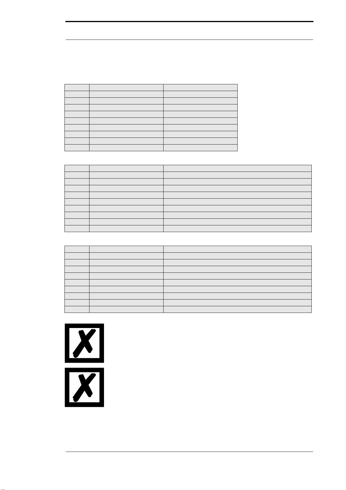
1.1.1 Symbols
Particularly important text sections can be seen from the adjacent pictogram.
You should always follow this information since, otherwise, this could result in
malfunctions or operating errors.
1.1.2 Concepts
The expressions ‘LOCON’, ‘ROTARNOCK’ and TERM are frequently used throughout this Man-
ual with no further model specifications. In such cases, the information applies to the entire
model series.
1.1.3 Suggestions
We are always pleased to receive suggestions and wishes etc. and endeavour to allow for these.
It is also helpful if you bring our attention to any errors.
Introduction Deutschmann Automation GmbH & Co. KG
12 Instruction manual LOCON 24, 48, 64 , LTC, TERM 24 and TERM 6 V. 8.8 24.7.12
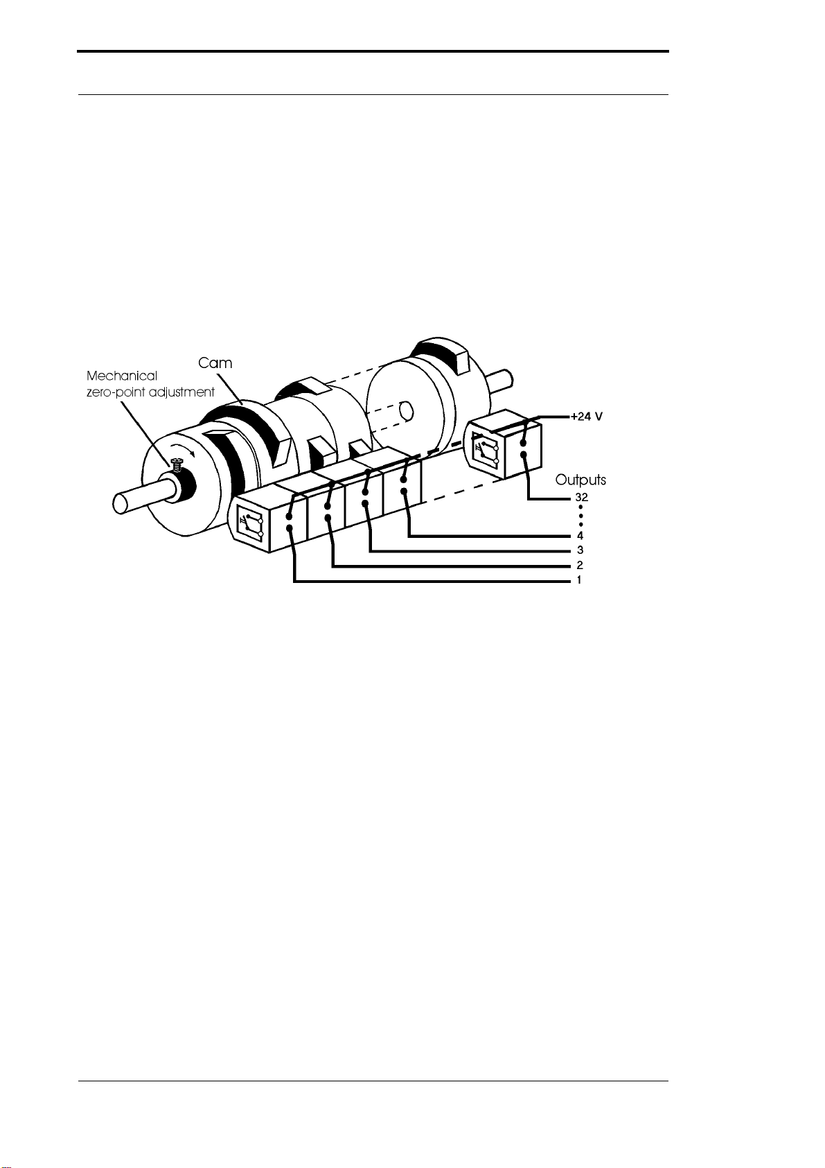
1.2 From the mechanical system to an electronic system
The purpose of electronic cam controls is not only to take the place of mechanical controllers but
to render their function more precise and simpler, to provide a universal range of application and
to reduce wear.
The mechanical cam control actuates a switch over sections of a circle, and this switch is closed
over the length of this section. Such a section is defined as a "cam".
Each switch represents one output. Several circuits arranged in parallel produce the number of
outputs.
Picture 1: Mechanical cam control
This basic principle has been adopted from the mechanical cam controls. A cam is programmed
for an output by entering a switch-on point and a switch-off point. The output is switched on
between these points.
Thanks to twenty years of experience, consistent further development and the use of ultra-mod-
ern technology, DEUTSCHMANN AUTOMATION has now become one of the leading suppliers
of electronic cam controls.
1.3 Deutschmann Automation’s range of products
A detailed and up-to-date overview of our product range can be found on our homepage at
http://www.deutschmann.de.

24.7.12 Instruction manual LOCON 24, 48, 64, LTC, TERM 24 and TERM 6 V. 8.8 13
Deutschmann Automation GmbH & Co. KG EMC Directives for products of DEUTSCHMANN AUTOMATION
2 EMC Directives for products of DEUTSCHMANN AUTOMATION
The installation of our products has to be carried out considering the relevant EMC directives as
well as our internal instructions.
For more information see ’EMC Directives’ on our homepage at http://www.deutschmann.com.

Electrical connections LOCON 24, 48, 64 Deutschmann Automation GmbH & Co. KG
14 Instruction manual LOCON 24, 48, 64 , LTC, TERM 24 and TERM 6 V. 8.8 24.7.12
3 Electrical connections LOCON 24, 48, 64
3.1 Rear view LOCON 24, 48, 64
X5X6X7
X4
X1
X2 X3
Picture 2: Rear view LOCON 24, 48 and 64 (only for devices from art.-no. V2237 on)
Devices with an article-no. lower than V2237 have a different pin assign-
ment. Therefore please order the instruction manual with the article-no.
V1249, version V 4.00 or make a download from our download-area on our
homepage at www.deutschmann.de.

24.7.12 Instruction manual LOCON 24, 48, 64, LTC, TERM 24 and TERM 6 V. 8.8 15
Deutschmann Automation GmbH & Co. KG Electrical connections LOCON 24, 48, 64
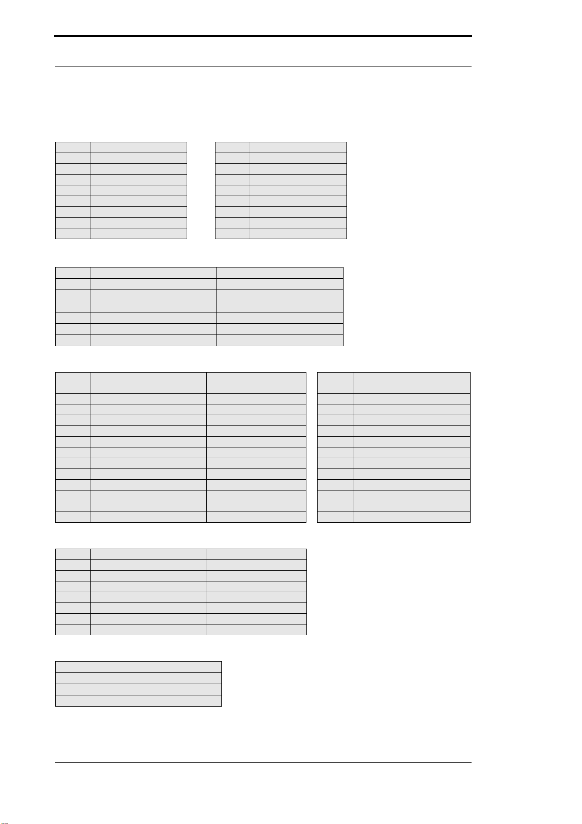
3.2 Pin assignment LOCON 24, 48, 64
3.2.1 Pin assignment X1 (2x24-pin screw terminals)
Pin-No. Significance Pin-No. Significance Option analog output
1Output 1 25 Output 25 Output 25
2Output 2 26 Output 26 Output 26
3Output 3 27 Output 27 Output 27
4Output 4 28 Output 28 Output 28
5Output 5 29 Output 29 Output 29
6Output 6 30 Output 30 Output 30
7Output 7 31 Output 31 Output 31
8Output 8 32 Output 32 Output 32
9Output 9 33 Output 33 Output 33
10 Output 10 34 Output 34 Output 34
11 Output 11 35 Output 35 Output 35
12 Output 12 36 Output 36 Output 36
13 Output 13 37 Output 37 Output 37
14 Output 14 38 Output 38 Output 38
15 Output 15 39 Output 39 Output 39
16 Output 16 40 Output 40 Output 40
17 Output 17 41 Output 41 I out 1
18 Output 18 42 Output 42 AGND
19 Output 19 43 Output 43 Vout 1
20 Output 20 44 Output 44 AGND
21 Output 21 45 Output 45 Iout 2
22 Output 22 46 Output 46 AGND
23 Output 23 47 Output 47 Vout 2
24 Output 24 48 Output 48 AGND
3.2.2 Pin assignment X2 (1x16-pin screw terminals)
LOCON 64 only
Pin-No. Significance Pin-No. Significance
49 Output 49 57 Output 57
50 Output 50 58 Output 58
51 Output 51 59 Output 59
52 Output 52 60 Output 60
53 Output 53 61 Output 61
54 Output 54 62 Output 62
55 Output 55 63 Output 63
56 Output 56 64 Output 64
Please note the differing pin assignment on units with binary-coded speed
display option. This different assignment can be found in chapter
Options: Speed display.
Electrical connections LOCON 24, 48, 64 Deutschmann Automation GmbH & Co. KG
16 Instruction manual LOCON 24, 48, 64 , LTC, TERM 24 and TERM 6 V. 8.8 24.7.12
3.2.3 Pin assignment X2 (1x16-pin screw terminals)
LOCON 24 and 48 with the option E16 only
Pin-No. Significance Pin-No. Significance
1Input 1 9Input 9
2Input 2 10 Input 10
3Input 3 11 Input 11
4Input 4 12 Input 12
5Input 5 13 Input 13
6Input 6 14 Input 14
7Input 7 15 Input 15
8Input 8 16 Input 16
3.2.4 Pin assignment X3 (1x6-pin screw terminals)
Pin-No. Significance for SSI-encoders RS422 incremental
1+24V - Encoder (Output) +24V - Encoder (Output)
2GND-Encoder GND-Encoder
3SSI CLK+ B+
4SSI CLK- B-
5SSI DAT+ A+
6SSI DAT- A-
3.2.5 Pin assignment X4 (1x24-pin screw terminals)
Pin-No. Significance for
absolute shaft encoders Significance for
incremental encoders Pin-No. Significance for
absolute shaft encoders
1+24V - Encoder (Output) 13 Encodertrack 11
2GND - Encoder 14 Encodertrack 12
3Encodertrack 1 15 Encodertrack 13
4Encodertrack 2 Preset Active + 16 +24V - Output
5Encodertrack 3 LatchClr+ 17 ProgEnable
6Encodertrack 4 SelectCount+ 18 ProgStart
7Encodertrack 5 Clear+ 19 PrgNr 1
8Encodertrack 6 OutEnable+ 20 PrgNr 2
9Encodertrack 7 CountEnable- 21 PrgNr 4
10 Encodertrack 8 Clear- 22 PrgNr 8
11 Encodertrack 9 Track A/Count23 PrgNr 16
12 Encodertrack 10 Track B/Down+ 24 PrgNr 32
3.2.6 Pin assignment X5 (1x7-pin screw terminals)
Pin-No. Device with RS485 Device with RS232
1+ 24V - Supply + 24V - Supply
2GND GND
3DICNET - Rx-LOCON
4DICNET + Tx-LOCON
5GND GND
6R- R-
7R+ R+
3.2.7 Pin assignment X6 (1x3-pin screw terminal)
Pin-No. Significance
1Run-On
2Run-Common
3Run-Off
24.7.12 Instruction manual LOCON 24, 48, 64, LTC, TERM 24 and TERM 6 V. 8.8 17
Deutschmann Automation GmbH & Co. KG Electrical connections LOCON 24, 48, 64
3.2.8 Pin assignment X7
3.2.8.1 Pin assignment X7 - Standard version (9-pin D-Sub female connector)
3.2.8.2 Pin assignment X7 at the Profibus-version
3.2.8.3 Pin assignment X7 at the MPI-version
The use of an integrated Gateway-technology may result in a signal-delay
on the fieldbuses of up to 10 ms.
Please note the signal description on the following pages!
Pin-No. 232 485
1nc nc
2 Rx-LOCON DICNET-
3Tx-LOCON DICNET+
4nc nc
5ØV-OUT ØV-OUT
6nc R-
7nc R +
8nc nc
924 V- OUT (max. 300 mA) 24 V-OUT (max. 300 mA)
Pin-No. Name Function
1not connected
2not connected
3 B not-inverted input-/output-signal from PROFIBUS
4not connected nc
5M5 DGND-data reference potential
6P5 5V supply voltage
7not connected
8 A inverting input-/output-signal from PROFIBUS
9not connected
Pin-No. Name Function
1not connected
2not connected
3 B not-inverted input-/output-signal from MPI-bus
4not connected nc
5M5 DGND-data reference potential
6P5 5V supply voltage
7not connected
8 A inverting input-/output-signal from MPI-bus
9not connected

Electrical connections LOCON 24, 48, 64 Deutschmann Automation GmbH & Co. KG
18 Instruction manual LOCON 24, 48, 64 , LTC, TERM 24 and TERM 6 V. 8.8 24.7.12
3.3 Signal description LOCON 24, 48, 64
Function Significance
Output 1 ... Output 8 Output block 1
Each output 24 V / 0.3 A positive-switching (PNP), short-circuit-proof
Total current of output block max. 1 A
Output 9 ... Output 16 Output block 2
Each output 24 V / 0.3 A positive-switching (PNP), short-circuit-proof
Total current of output block max. 1 A
Output 17 ... Output 24 Output block 3
Each output 24 V / 0.3 A positive-switching (PNP), short-circuit-proof
Total current of output block max. 1 A
Output 25 ... Output 32 Output block 4
Each output 24 V / 0.3 A positive-switching (PNP), short-circuit-proof
Total current of output block max. 1 A
Output 33 ... Output 40 Output block 5
Each output 24 V / 0.3 A positive-switching (PNP), short-circuit-proof
Total current of output block max. 1 A
Output 41 ... Output 48: Output block 6
Each output 24 V / 0.3 A positive-switching (PNP), short-circuit-proof
Total current of output block max. 1 A
Output 49 ... Output 56: Output block 7
Each output 24 V / 0.3 A positive-switching (PNP), short-circuit-proof
Total current of output block max. 1 A
Output 57 ... Output 64: Output block 8
Each output 24 V / 0.3 A positive-switching (PNP), short-circuit-proof
Total current of output block max. 1 A
+24V - Output 24 V output for Prog-Enable and external program selection
+24V - Supply 24 V power supply for overall units, including output drivers
+24V - Encoder 24 V output voltage for encoder (max. 300 mA)
GND Ground potential of the overall cam control. All GND signals are interconnected
internally. There is no connection to chassis which must be connected to the
equipotential bonding system.
TxD-LOCON RS232 transmit line
RxD-LOCON RS232 receive line
SSICLK+, SSICLK- RS422 clock line pair for SSI interface
SSIDAT+, SSIDAT- RS422 data line pair for SSI interface
RunOn, RunCommon, RunOff
(only LOCON 24, 48, 64) Floating fault alarm changeover contact. Max. contact load of the Run-Control
relay: 100 V DC/V AC, 1 A
Connection Common - On: Unit OK
Connection Common - Off: Fault
DICNET+, DICNET- Data line for networking via the DEUTSCHMANN bus system DICNET® (see
also chapter DICNET).
R+, R- Termination resistor terminals for DICNET. Required if LOCON 32 is operated
as the first or last device in the DICNET (see chapter DICNET)
Encodertrack 1 - Encodertrack 13 24 V input (max. 10 mA) for encoder leads if using absolute shaft encoders up
to 8,192 information items/rev. with parallel output
IncTrackA Connection of track A if using an incremental encoder 24 V
IncTrackB Connection of track B if using an incremental encoder 24 V
LatchClr If this input is wired to 24 V, the Clear pulses (see below) are latched, i.e. a
pulse with a minimum length of 40 µs is interpreted as Clear. This Latch func-
tion should be used only in the case of really short Clear signals since the Clear
input in this case also responds more sensitively to interference signals. If the
input is not wired or is wired to 0 V, a minimum Clear length of 1 ms is required.
SelectCount+, Count^, Down+ If 24 V is applied to this input, inputs ”Encodertrack9” and ”Encodertrack10” are
evaluated as counting and direction input. A pulse is incremented with each
rising edge at ”Count”. If input "Down+" has 24 V, downcounting is carried out.
Otherwise, upcounting is carried out. If ”SelectCount+" is not wired or is wired
to 0 V, an incremental encoder with A/B tracks is expected.
24.7.12 Instruction manual LOCON 24, 48, 64, LTC, TERM 24 and TERM 6 V. 8.8 19
Deutschmann Automation GmbH & Co. KG Electrical connections LOCON 24, 48, 64
3.3.1 Status LEDs
3.3.1.1 Front view
48 LEDs indicating the output status (LED on = 24 V at output) are arranged beneath the seven-
segment display. The status of outputs 49 to 64 on LOCON 64 is not displayed.
3.3.1.2 Rear view
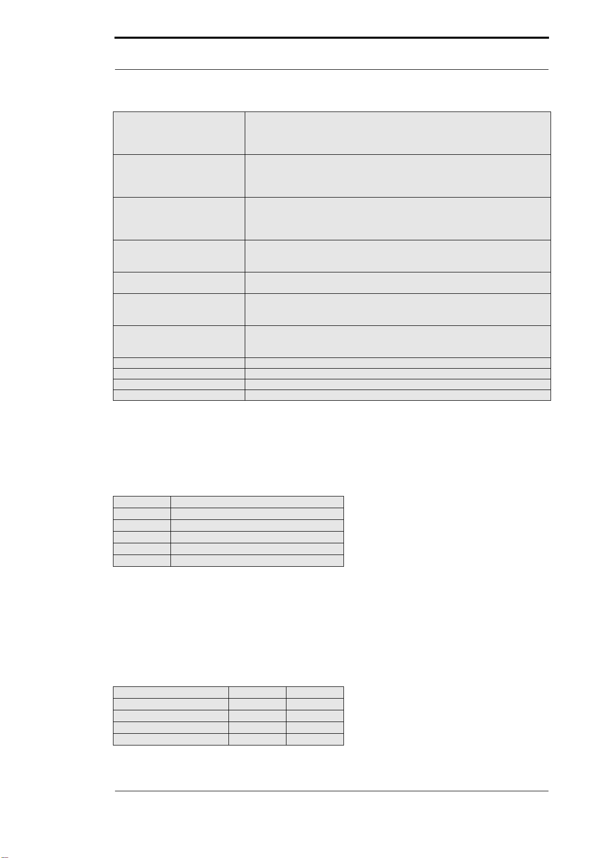
3.4 External program selection
For external program selection, the new program must be applied in the form of binary code (see
chapter "Coding device and program numbers") at the connector strip and then a leading edge
must be generated at pin "ProgStart", whereby the High level (24 V) must be held for at least 200
ms.
The following steps are required if, for example, program 7 (binary 000111) is to be activated:
3.4.1 Applying the corresponding voltages
Clear-, Clear+ Clear pulse. As soon as one of the two signals is activated (0 V in the case of
Clear-, 24 V in the case of Clear+), the count is set to 0 and is maintained at 0
until the Clear condition disappears again. The pulse width is dependent on
wiring of input "LatchClr" (see above).
CountEnable- This signal enables the counter in the case of 0 V or if unwired. If
24 V is applied to this line, the count is frozen. The speed measurement and,
thus, the TZK continue to run during this time.
This signal is evaluated with an accuracy of ±0.5 ms.
OutEnable+ This signal can be used to connect and disconnect the outputs if incremental
encoders are used. In the case of 0 V or unwired, the outputs are deactivated.
In the case of 24 V, the outputs are set in accordance with the programmed
cams. The response to a signal change occurs with an accuracy of ±0.5 ms.
Prog.No. 1 ... Prog.No. 32 The program number is applied to these pins in the case of an external pro-
gram selection. Coding is in binary form in accordance with chapter ”Coding
device and program number”.
ProgStart If 24 V is applied to this pin, the program number at pins Prog.No.1 to
Prog.No.64 (see above) is accepted.
ProgEnable If 24 V is applied to this pin, all parameter changes (including configuration
change) are allowed in LOCON. Please refer to chapter ”Programming enable”
for further details.
Input 1-16 Logic inputs
Each input 24 V (max. 10 mA).
Please refer to chapter ”Logic inputs” for further details
nc Not connected
I out Analog output (power)
V out Analog output (voltage)
AGND Reference for analog outputs (Iout + Vout)
LED Significance
Error Error (see chapter „Error messages“)
Stop Run-Control off
Run DICNET selected
Power Internal voltage ok
SST SSI-connection ok
Pin Volt Binäry
PROG_NR32 0V 0
PROG_NR16 0V 0
PROG_NR8 0V 0
PROG_NR4 24V 1
Electrical connections LOCON 24, 48, 64 Deutschmann Automation GmbH & Co. KG
20 Instruction manual LOCON 24, 48, 64 , LTC, TERM 24 and TERM 6 V. 8.8 24.7.12
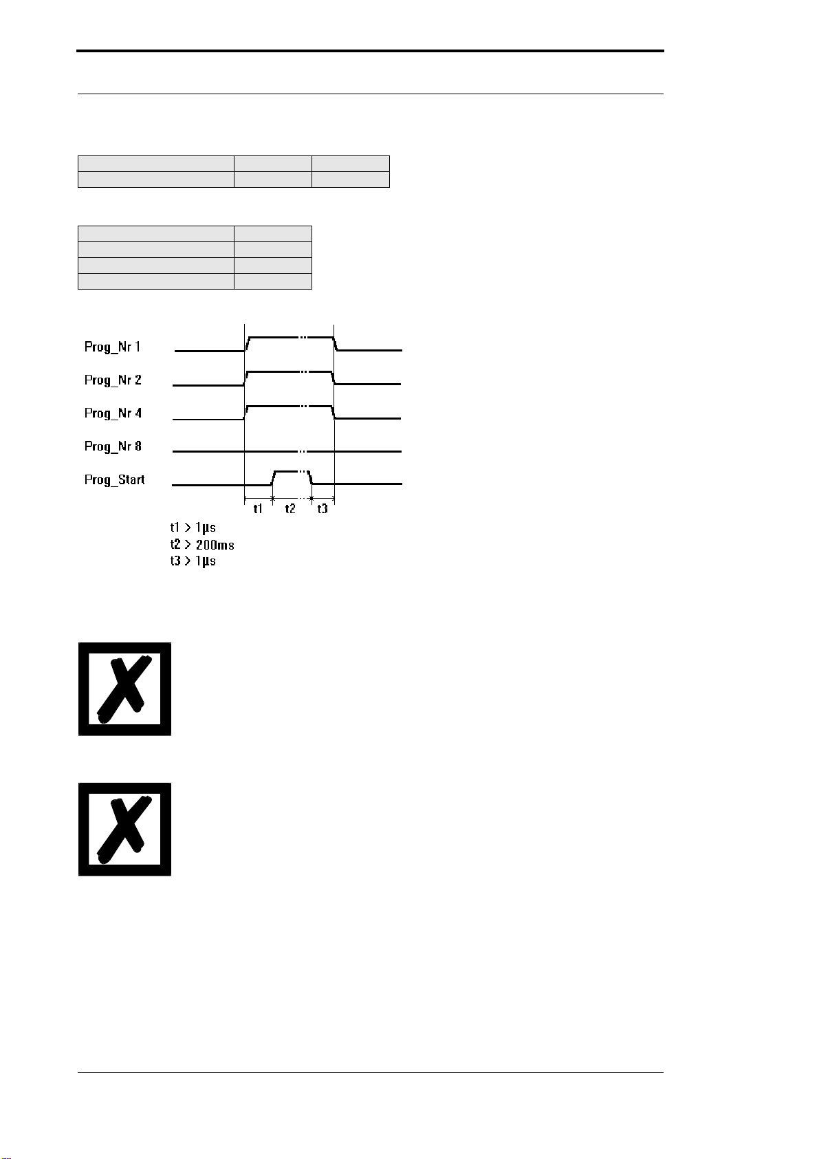
3.4.2 Generation of the acceptance edge
Pin Volt
PROG_START = 24V 24V
Wait 200ms
PROG_START = 0V 0V
3.4.3 Graphic representation of program selection
Picture 3: Program selection
The program can be changed at any time using the connector strip.
If pin "PROG_START" is permanently wired to 24 V, LOCON accepts the
program applied externally each time the unit is powered up.
3.5 Installation and commissioning of LOCON 24, 48 and 64
The screw-type plug connectors of the LOCON may be unplugged and
plugged in only with the power supply disconnected!!!
3.5.1 Connection of the supply voltage
The supply voltage is 24V DC (+/- 20%) and is applied to pins "+24V". The reference ground is
wired to "GND". The LOCON requires maximum 200 mA when not under load and not including
encoder power supply.
The corresponding inputs and outputs must be wired before switching on the supply voltage in
order to avoid malfunctions.
PROG_NR2 24V 1
PROG_NR1 24V 1
This manual suits for next models
5
Table of contents
Popular Industrial Electrical manuals by other brands

Siemens
Siemens RAJA+ 3TE7421 Installation, operation & maintenance instructions

Murata
Murata GRM1885C1H5R1BA01 Series Reference sheet

Murata
Murata GRM1555C1H301GA01 Series Reference sheet

Siemens
Siemens 3TC74 operating instructions

Murata
Murata GRM0335C2A6R3CA01 Series Reference sheet

Murata
Murata GRM1555C1H5R0CA01 Series Reference sheet


Eaton
Eaton CI-K2 Series Instruction leaflet

Murata
Murata GRM1555C1E4R2CA01 Series Reference sheet

Murata
Murata GRM32AR61C106KAB7 Series Reference sheet

Murata
Murata GRM2165C1H101JA01 Series Reference sheet

Murata
Murata GRM1885C1H560GA01 Series Reference sheet

Siemens
Siemens SIVACON 8PS installation instructions