dfv CP-M1250 User manual
DFV-N50/93-02
Aug. 2002
CP-M1250
CP-M1230
INSTRUCTIONS
D.F. Vasconcellos S/A
High Precision in Optics and Mechanics Technical Publications Dept.
COLPOSCOPE

DFV-N50/93-02
Aug. 2002
THE COMPANY AND ITS PRODUCTS
D.F. VASCONCELLOS, with over half a century of existence, was the
first Brazilian industry specialized in the production of precision optical
instruments. It has grown ever since, its expansion being headed to the
meeting of prospective markets, without ever failing to meet its products
reliability.
Such a direction provided D.F.VASCONCELLOS with international
prestige, its trademark ranking among the best existing ones, disputing the
preference of the most demanding consumers in over 40 countries to where
its products are currently exported.
Diversification is also a part of D.F.VASCONCELLOS history. In the first
decade after its foundation, it started producing a number of special
instruments for the Brazilian army, on exclusive basis, such as telemeters,
binoculars, goniometers-compasses and observation eye-glasses, which
were until then supplied by advanced-technology countries. A gap of
strategic importance became so bridged, with contribution to nation’s
economy by saving important monetary availabilities.
By continuing its policy of supplying the domestic market with items still
depending on importation, the first devices specially designed for
ophthalmologic operations, otorhinolaryngology, and microsurgery in
general and gynecology, were launched 35 years ago. By developing its
own know-how, through the most strict researches, under the guidance of a
competent team of physicians specialized in those sectors, the “Medical
Line” of D.F.VASCONCELLOS is one more realization that raises the
Brazilian industry to international levels.
ISO 9001 certified, the company develops continuous improvement
process, to match customer’s satisfaction.
This Manual is a summary of the quality and sophistication of the
microsurgery instruments manufactured by D.F.VASCONCELLOS.
1

DFV-N50/93-02
Aug. 2002
D.F.VASCONCELLOS S/A
High precision in optics and mechanics
D.F.VASCONCELLOS S.A.
High precision in optics and mechanics
Address: Av. Indianópolis, 1706
04062-901-São Paulo-Brazil
Phone: 55-11-5584-0411
E-Mail: [email protected]
Fax: 55-11-5585-2300
Mail Box: 45.349-CEP 04010-970 - São Paulo - SP
2

DFV-N50/93-02
Aug. 2002
I - TABLE OF CONTENTS
ITable of contents....................................................... 3
II Foreword.................................................................... 4
III Technical Data .......................................................... 5
IV Colposcope Description ..................................... 6
a - Optical Head
b – Floor Stand
c - Illumination
VComplete assembly of the colposcope head 13
VI Colposcope Handling................................................ 14
a) Magnification selector
b) Progressive brakes
c) Focal point
d) Colposcope focalization
e) Interpupillary distance adjustment
f) Green filter
g) Pantographic arm balancing
VII Optical and field Magnification Table.................... 17
VIII Maintenance 18
a) Lubrication
b) Cleaning
c) Lamp examination
d) Electric connections
e) Replacement of the Colposcope Lamp
f) Electric system
IX Accessories................................................................. 22
XWarranty................................................................... 23
3

DFV-N50/93-02
Aug. 2002
II - FOREWORD
This manual is intended to give assistance in the assembly and operation of the
Colposcope Series CP-M1250/1230.
The Colposcope Series CP-M1250/1230 is multi-purpose equipment suited for
diagnostic practice and general microsurgery in the field of gynecology.
We shall demonstrate in the following sections the applicable accessories to the above
specialties.
You shall wait for an authorized technician to assemble the equipment.
This handbook includes a chapter to acquaint the user with the assembly process, which
could be followed up by the user.
Read this handbook carefully prior to operating the colposcope.
Do not allow that persons unfamiliar with the equipment operate the colposcope.
The installation of the equipment by non-authorized personnel will imply in loss of the
factory warranty.
ATTENTION:
Cares to handle the Optical Fiber Cable:
•Do not fold, bend or squash the Optical Fiber Cable,
under risk of damage.
In its structure there are hundreds of fibers, that can break in case this is done, reducing
considerably the light flux. If you need to remove (cleaning, service, etc), roll it up on a
5cm (2in) minimum radius, and keep it in a protected place. Special attention must be
kept near the ends, at the terminals, where naturally it is more rigid, and do not allow
bends.
4

DFV-N50/93-02
Aug. 2002
III - TECHNICAL DATA
A - Colposcope Head
1 Colposcope Galilean System
2 Straight binoculars Porro type, focus 160 mm
3 Objetive (focus) 300 mm
4 Eyepiece (two) Wide angle type 12,5X; adjustable
5 Magnification See table
6 Observation field See table
7 Illumination field See table
8 Interpupillary distance Adjustable between 55 mm and 75 mm
9 Illumination
a – Source 1 dichroic halogen 15V/150W lamps
b - Light conductor Coaxial Optical fiber with 6 mm active
diameter and 1300 mm length
c – Filter
11 Focusing
a - Macro By moving the pantographic arm
b – Micro Manual with rack and pinion
12 Total weight of the head 2.750 Kg
B- Colposcope stand
1 Horizontal reach 1024 mm. - first arm 400 mm, second arm
514 mm, third arm 110 mm.
2 Vertical reach 580 mm
3 Angular rotation 340º
4 Distance between the floor and the objective 910 mm to 1490 mm
5 Load adjustment 4 to 7 kg
6 Counterweight 35.6 kg
7 Base Base with five casters, two with brakes
8 Total floor stand set weight 51.7 kg
5

DFV-N50/93-02
Aug. 2002
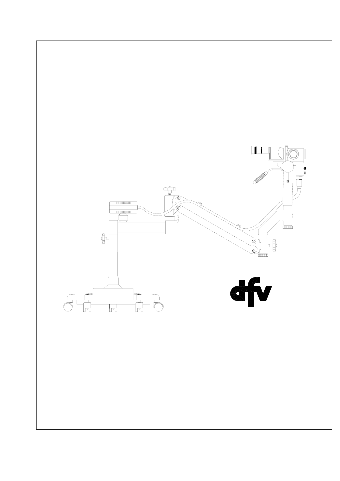
IV- COLPOSCOPE CP-M1250/1230 DESCRIPTION
1
3
2
FIGURE 1
1) Optical head with binocular
2) Floor stand set
3) Cold light generator
6

DFV-N50/93-02
Aug. 2002
IV - a - COMPLETE OPTICAL HEAD
FIGURE 2
1) Optical head
2) Inclined and straight binoculars
3) Objective
7

DFV-N50/93-02
Aug. 2002
IV-a-1 - OPTICAL HEAD
FIGURE 3
1) Body
2) Objective
3) Magnification selector
4) Green filter lever
5) Focusing knob
6) Optical fiber connector
7) Brake lever
8) Fork
9) Shank pin
10) Dovetail rule
11) Guide pin
12) Binocular support flange
13) Binocular fixing screw
14) Safety Knob
15) Protecting ring
8
DFV-N50/93-02
Aug. 2002
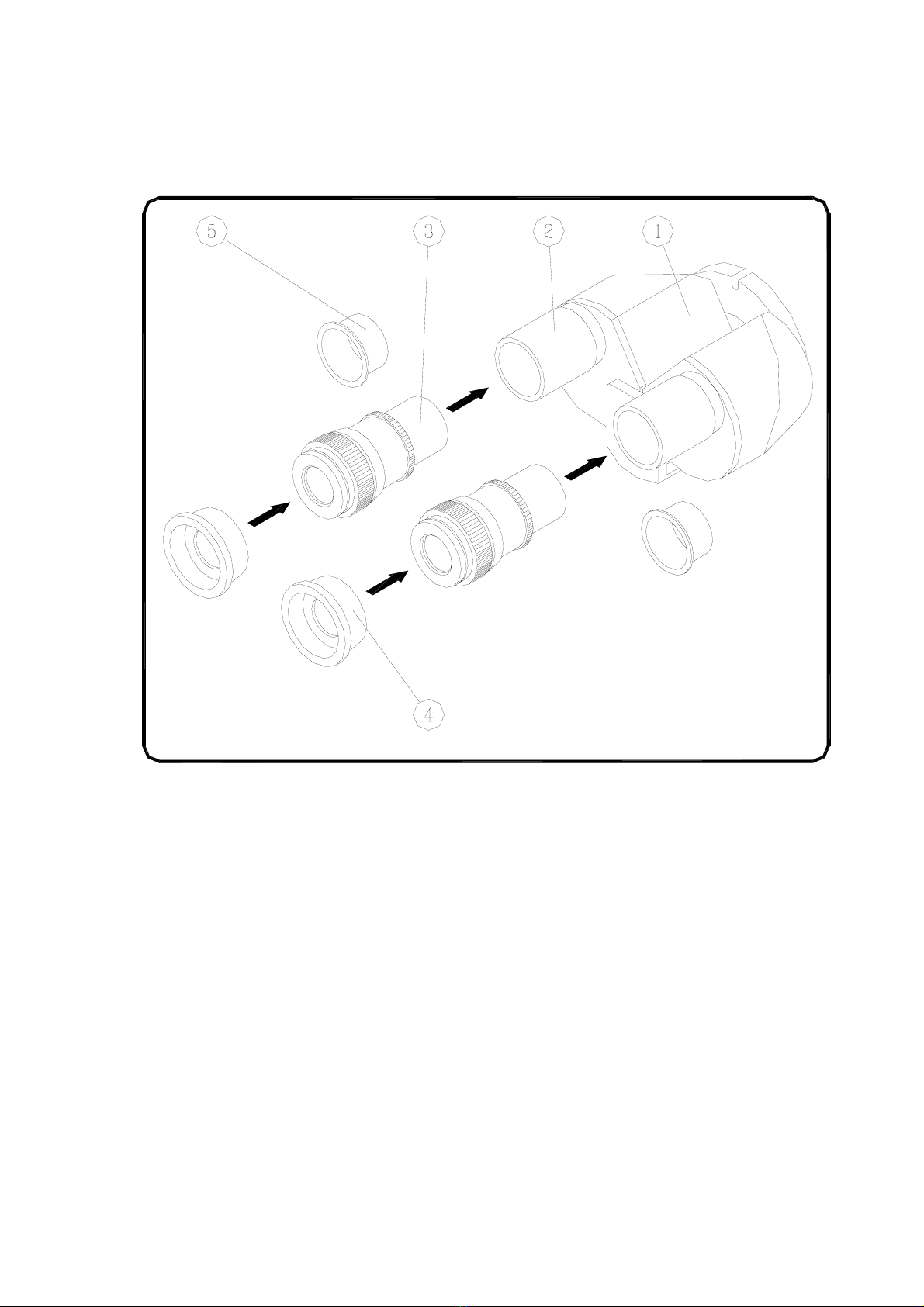
IV-a-2 - STRAIGHT BINOCULARS
FIGURE 4
1) Binoculars body
2) Eyepiece tube
3) Eyepieces with diopter adjustment
4) Eye protectors
5) Binocular protection plugs
Note: The data given is also valid for inclined binoculars
9

DFV-N50/93-02
Aug. 2002
IV-a-3 - OBJECTIVE
The colposcopes are shipped by the factory with the following objective:
F = 300 mm
The following objectives are available as options:
F = 175 mm
F = 200 mm
F = 250 mm
F = 350 mm
F = 400 mm
10
DFV-N50/93-02
Aug. 2002
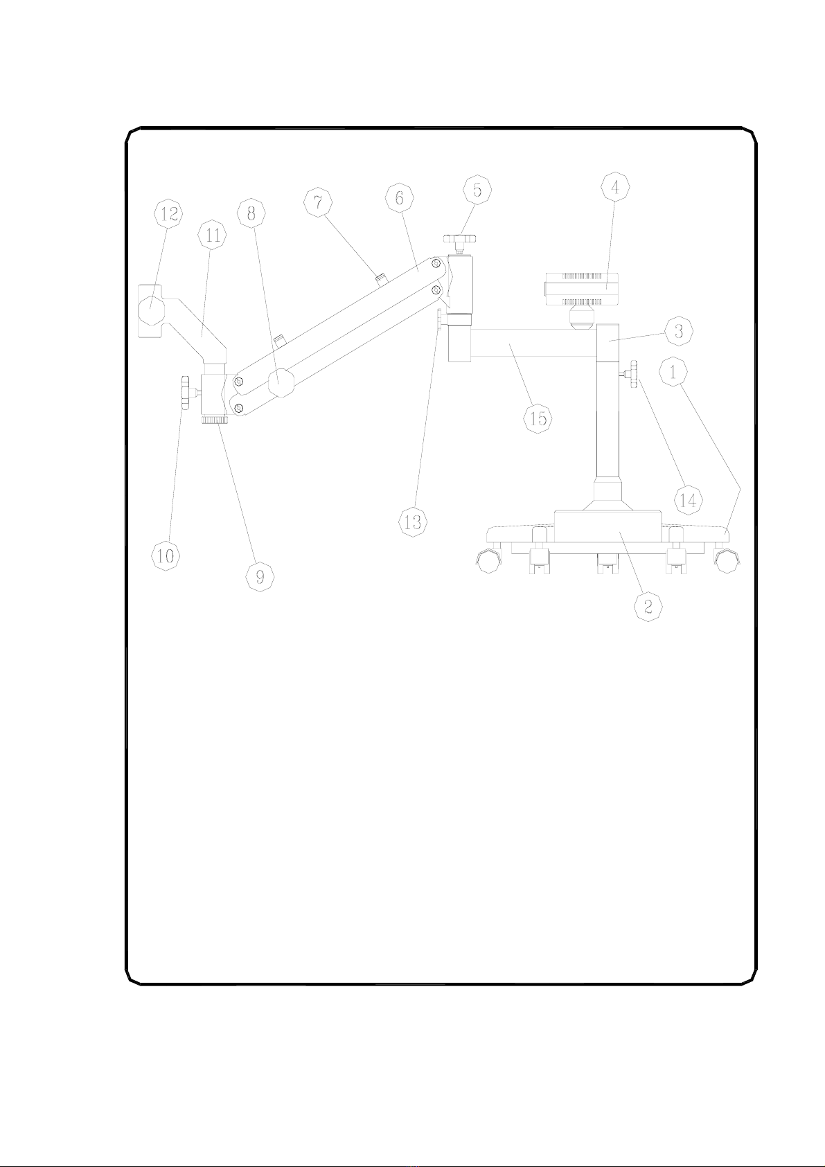
IV - b) FLOOR STAND SUPPORT
FIGURE 5
1) Base with 5 trundles and five casters
(two with brakes)
2) Counterweight
3) Column
4) Cold light generator
5) Balance Knob
6) Pantographic forearm II
7) Clamp for light conductor
8) Vertical movement lock knob
9) Vertical safety knob
10) Terminal lock knob
11) Terminal
12) Optical head lock knob
13) Forearm lock knob
14) Arm I lock knob
15) Arm I
11
DFV-N50/93-02
Aug. 2002
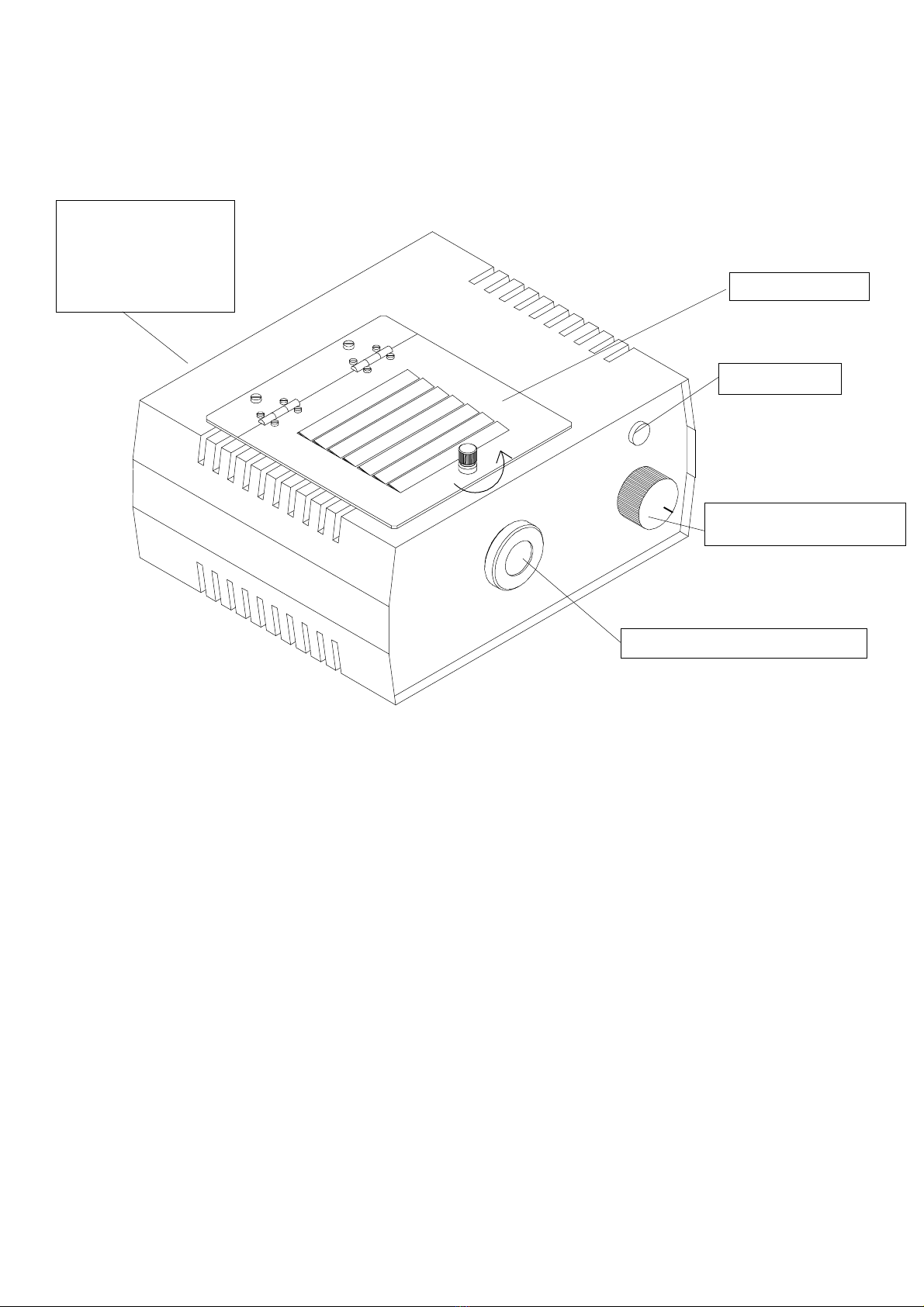
IV – c - COLD LIGHT GENERATOR
REAR PART
- Wire access
- 02 fuses 2.5 A
- Reversible switch
- Identification plate
On/Off switch with
potentiometer
Connector for fiber optic cable
Lamp housing
Pilot lamp
FIGURE 6
This illumination system is called "cold light", since it does not allow the passage of the
heat radiation. It consists basically of the generator (Figure 6), illumination terminal for
fiber optic and fiber optic cable, making the connection between the two parts.
As shown in Figure 6, the generator panel is composed basically of a pilot lamp, a
connector for the fiber optic cable and an ON/OFF switch with potentiometer that
allows the adjustment of the intensity of light in the Microscope.
If the socket’s voltage is not the same as the microscope’s voltage, remove the 2 screws
that fix the identification plate (Figure 6) and change the voltage to the desired value.
IMPORTANT: As a last recommendation, it is highly convenient that the local
electrical tension be connected to a voltage regulator, and this one (properly adjusted to
the rated voltage) will be then connected to the cold light generator here represented,
being so ensured that the overload operations will remain within bearable limited
ranges, which should not be surpassed by unexpected variations of the local electric
tension.
12

DFV-N50/93-02
Aug. 2002
V - COMPLETE ASSEMBLY OF THE COLPOSCOPE HEAD
Remove from the packing case with maximum care:
a) Optical head
b) Binoculars
c) Eyepieces and protectors
1. Head assembly
Introduce the shank pin (item 9-figure 3) into the terminal (item 11-figure 5). Screw the
safety knob (item 14-figure 3) and lock the shank pin with knob (item 12 –figure 5).
2. Binoculars assembly
At first release the screw that fixes to the body (item 13, Figure 3). Place the binoculars
(item 1, Figure 4) on the flange of the body making sure that the pin fits into the slit of
the binoculars flange.
Tighten the fixing screw and make yourself sure that the binoculars are firmly secured
to the colposcope.
3. Eyepiece mounting
a) Eyepiece installation into the binoculars
The eyepieces shall be introduced into the binocular tubes until the relief touches the
edge of the tube.
b) Installation of the eye protectors
The internal rib of protector shall be fitted in the groove at the top of the eyepiece. Their
purpose is to protect the eyes from the surrounding light (false light) setting up a
darkroom to improve and facility watching.
Many times they are also used to make small corrections of the image place.
13

DFV-N50/93-02
Aug. 2002
VI - COLPOSCOPE HANDLING
a- MAGNIFICATION SELECTOR
The magnification selector has 6 positions: A/6, B/10, C/16, D/25, E/40.
The C/16 position is repeated in the selector.
The position being used in the one that stands before the red mark on the body.
The magnification factors engraved near the letters are given for the 20x eyepiece,
160 mm focus binocular and 200 mm focus objective. Other magnifications are found
in the table appended.
b- PROGRESSIVE BRAKES
The progressive braking system allows small adjustments of the colposcope position
during surgery or clinic examination.
The lever (item 7-figure 3) progressively restrains the rotating movement of the head.
The movement of the brake is clockwise (Figure 7) when the observer is in front of it.
FIGURE 7
14

DFV-N50/93-02
Aug. 2002
The figure shows the lever unscrewed and removed, and the fixation hole. There are
five more holes that are covered by the protective ring, which are seen successively as
the ring is turned, as indicated in the figure.
The progressive brake made from fiber washers and a pressure spring ensures light
and progressive pressure on the head rotation.
The brake system also permits that:
After the locking of the head, the lever can be kept in different positions. Therefore,
unscrew the lever; turn the ring that covers 5 holes and screw in another opening,
according to Figure 7.
Finally we recommend that the lever should stay ALWAYS SMOOTHLY BREAKED
to guarantee immobility on the chosen position, permitting small movements on the
rotating head, without moving the break lever.
c- FOCAL POINT
The micro-focusing is done mechanically by means of a rack and pinion guided by a
dovetail and can be actuated with 2 knobs (item 5 - Figure 3), one at each side.
Focusing corrections are unnecessary for the smaller magnifications when maximum
magnification is used in focusing.
The field focusing uses only one eye, possibly with 0 dioptries One eyepiece scale
shall be adjusted to 0 dioptries, while locking the other. Focusing is then made turning
the micro focusing micrometric motion knobs (item 5 - Figure 3) in the clockwise and
counterclockwise directions until the field is clearly seen.
Then, using only the other eye, focus the field turning the eyepiece ring in the
clockwise and counterclockwise directions.
d- COLPOSCOPE FOCALIZATION
Fix the eyepiece to the field to be observed. Make the distance to the observation field
the same number of millimeters as the focal distance of the objective being used.
EXAMPLE: The distance of the field to the objective shall be 200 mm when a 200mm
focal distance objective is being used.
NOTE: It is easier to locate the field when the emerging light beam is on.
e- INTERPUPILLARY DISTANCE ADJUSTMENT
Watch with both eyes, through the eyepieces, the object to be magnified. Get the tubes
that support the eyepieces close and then apart with soft turning movements, over
imposing the images until the field vision comes out in a single disk, clear and
stereoscopic.
It is basic to obtain a clear and stereoscopic view that will remain assured by the
colposcope after a properly made focusing.
15

DFV-N50/93-02
Aug. 2002
f- GREEN FILTER
If the operator considers it necessary, a green filter may be interposed between the
illumination and the objective, which is done with the help of the filter knob (item 4 -
Figure 3).
g- PANTOGRAPHIC ARM BALANCING
At the factory, the colposcope is pre-adjusted for balancing, using the normal optical
head, and may only require adjustment at the tension knob (item 5-figure 5) when the
operator is using accessories.
16
DFV-N50/93-02
Aug. 2002
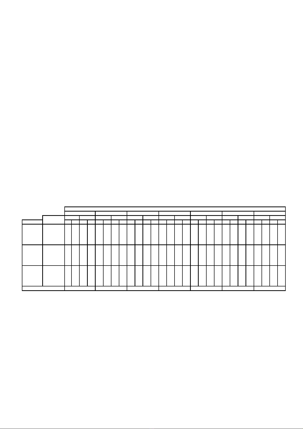
VII – OPTICAL AND FIELD MAGNIFICATION TABLE
The optical magnification achieved with the colposcope are determined by 3 variables:
the objective focal distance, the position of the Magnification Selector and the by
eyepiece used.
The table shows the optical magnification and the observed field diameters, in
millimeters, depending on those variables. At the bottom line of the table the
illumination Field is shown, corresponding to the light disk incident on the field, with a
diameter that depends only on the focus of the work objective.
The magnification selector bas 6 positions: A, B, C, D, C and E. The C position is
repeated in the selector. The working position is the one corresponding to the letter
standing before the red mark.
The CP-M1250 and CP-M1230 colposcolpes have the same basic configuration as
related in item III-A, the diference between them is that the CP-M1250 has a
magnification selector with six positions and five magnifications (A, B, C, D and E) and
the CP-M1230 has a four position selector and three magnification (B, C and D).
Magnification and field table for binoculars focus = 125 and focus = 160 mm
# microscope with 5 magnifications selector #
OBJECTIVES
100 175 200 250 300 350 400
KNOB magnification field magnification field magnification field magnification field magnification field magnification field magnification field
EYEPIECE POSITION f125 f160 f125 f160 f125 f160 f125 f160 f125 f160 f125 f160 f125 f160 f125 f160 f125 f160 f125 f160 f125 f160 f125 f160 f125 f160 f125 f160
A/6 (0.4)
B/10 (0.6) 7102317 4 63829 4 54334 3 45242 3 36550 2 37659 2 38767
10X C/16 (1.0)
D/25 (1.6) 19 26 9 6 12 15 15 11 10 13 17 13 9 10 20 16 7 9 25 19 6 7 29 23 5 7 33 26
E/40 (2.5)
A/6 (0.4)
B/10 (0.6) 10 13 23 17 6 7 38 29 5 6 43 34 4 5 52 42 3 4 65 50 3 4 76 59 3 3 87 67
12.5X C/16 (1.0)
D/25 (1.6) 25 33 9 6 15 19 15 11 13 16 17 13 11 13 20 16 9 11 25 19 8 9 29 23 7 8 33 26
E/40 (2.5)
A/6 (0.4)
B/10 (0.6) 15 20 13 10 9 11 22 17 8 10 25 19 7 8 29 24 5 7 37 29 4 6 43 33 4 5 49 38
20X C/16 (1.0)
D/25 (1.6) 3852 5 42330 8 62026 9 7172111 9141714111215161310131915
E/40 (2.5)
ILUMINATED FIELD 2
5
44 50 62 7
5
88 100
5 7 35 26 3 4 58 45 3 3 66 52 2 3 79 65 2 2 99 78 2 2 115 90 1 2 132 103
12 16 14 11 7 9 24 18 6 8 27 21 5 6 32 26 4 5 40 32 4 5 47 37 3 4 54 42
29 40 6 4 17 26 10 7 16 20 11 8 13 16 13 11 10 13 16 13 9 11 19 15 8 10 22 17
6 8 35 26 4 5 58 45 3 4 66 52 3 3 79 65 2 3 99 78 2 2 115 90 2 2 132 103
15 20 14 11 9 11 24 18 8 10 27 21 7 8 32 26 5 7 40 32 5 6 47 37 4 5 54 42
38 50 6 4 23 29 10 7 20 25 11 8 17 20 13 11 13 17 16 13 12 14 19 15 10 13 22 17
10 13 20 15 6 7 33 26 5 7 37 29 4 5 45 37 3 4 56 44 3 4 65 51 3 3 75 58
24 32 8 6 14 18 13 10 13 16 15 12 11 13 18 15 8 11 23 18 7 9 26 21 6 8 30 24
59 80 3 2 35 46 5 4 31 40 6 5 26 32 7 6 21 27 9 7 18 23 11 8 16 20 12 10
17

DFV-N50/93-02
Aug. 2002
VIII - MAINTENANCE
WARNING: Once a year a short revision shall be made, including:
a) Lubrication;
b) Cleaning up;
c) Lamps examination;
d) Electric connections;
e) Spare lamps: at least two spare lamps shall be kept to avoid losing time with
equipment unavailability and larger damages to the colposcope.
a) LUBRICATION
At the colposcope head there is a point that requires lubrication after some time of use.
It is the microfusing system that is called, in the mechanics jargon, “dovetail”. It
works by sliding, and Figure 8 shows it in extended position.
FIGURE 8
18

DFV-N50/93-02
Aug. 2002
b- CLEANING
The objective, fixed before the field under clinical treatment or surgery, is exposed to
bloodstains and drips of topic medicines, etc.
The stains blur the light path reducing the luminosity of the optical observation.
Cotton padding wetted in alcohol or ether rubbed softly, in CIRCULAR
MOVEMENTS over the optical surface, are enough to clean the stains, except those of
clot blood. Clot blood shall be cleaned with cotton wetted with hydrogen peroxide.
If the eyepieces are too dirty, change the cotton at each circular friction motion to
avoid spreading out the dirt.
On the other hand, we would like to remind that there is an effective protector for the
eyepiece, the MC-A40 (as an accessory) fitted under pressure at the outer edge of the
eyepiece and protecting it against eventual hits from surgery instruments and
contamination. The MC-A40 can be sterilized.
To have the eyepieces and objective well cleaned at the time of clinical of surgery use
it is enough use cotton head cleaners wetted with alcohol or ether.
The metallic parts (chromium plates or painted) shall be cleaned with cotton, alcohol
and ether.
c - LAMP EXAMINATION
1 - Generator pilot lamp
The pilot lamp indicates that the electric system is operating. If the lamp does not lit
when the equipment is turned on, check the fuses and main’s power.
2 - Illumination lamp
- Check if the two contacts at the rear are not oxidized.
- Check the lamp bulb is not darkened.
- The bulge at the reflector edge shall be well fit in the window of the support.
-The socket shall be fitted in the lamp’s pins.
d - ELECTRIC CONNECTIONS
Check for:
Wires are broken inside cable.
Wires are loose at the plug.
Wires are broken at the fixation inside the plug.
Oxidized plug’s pins
19
This manual suits for next models
1
Table of contents


