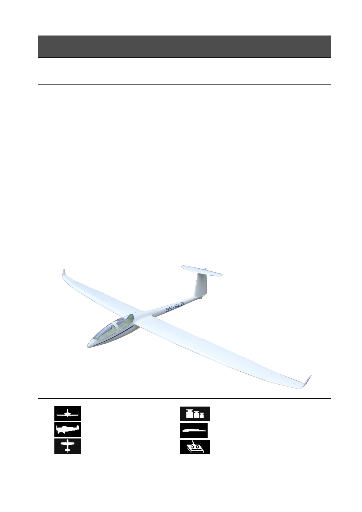
DG Flugzeugbau DG-1001 Instruction Manual
Thank you for your purchase this up-to-date sport semi-scale glider model,
designed for slope soaring, where you will appreciate it´s maneuvereability and
nice flying characteristics.
This is an absolute gorgeous reproduction of the famous DG-1001 from DG
Flugzeugbau GmbH from Germany. You have here an accurate 1:8 scale version,
in all molded technology. At 1:8 scale this should be a small scale glider, but the
high aspect ratio of the wing makes it still a comfortable sized plane of 2.5 m span.
Original forward swept wing plan-form, double taper elevator, installed airbrakes.
Designated for the intermediate pilot this is not the easiest plane to fly. It can be
pitch sensitive at high speed. But heck what a great look in the air. The wing does
not have flaps. It can be histarted, winched or aero towed. Also nice on the slope.
Radio requirements are four micro servos for the ailerons and airbrakes, one micro
for the elevator, one for the rudder. An additional servo might be installed for
aerotow.
Kit includes:
All fiberglass 1/8 scale sailplane
DG-1001
Building instructions
2500 mm 700 g (empty)
1090 mm S 3021
29 dm2 A, E, R, B

* fiberglass fuselage,
* fiberglass wing, double-high airbrakes installed,
* winglets
* horizontal stabilizer,
* rudder,
* canopy,
* canopy frame,
* wing connecting rod,
* bag with accessories
* stickers,
* building instructions
To finish the model you need:
* cyanoacrylate glue,
* 5-min epoxy glue,
* common modeller’s tools (sharp knife, drilling machine, screwdriver, fine round file,
sandpaper)
To fly you need:
* 4 channel RC set and 6 servos (at least 5 of them micro size)
Attention! Thank you to us immediately, if you note a missing part or a damaged part. We
cannot control the dexterity of the modeler and cannot influence the builder during the assembly
or the use of this radiocontrolled model, thus we will in no way accept or assume responsability
or liability for damages resulting from the use of this user assembled product.
You are responsible for running this model. A damage to property or health might arise by
improper use of this product. This is why you have to keep a safe distance from the buildings and
other developed areas when flying. Make sure that you are the only one who is flying on the
same waveband.
The product may only be used by the children over 14, supervised by adults.
The purchaser/user accepts all the responsibilities in the event of structural or mechanical
problems.
Warning, this is not a toy!
FINISHING THE MODEL
The glider is ready to fly right after the installation of the RC set.
1. How to install the rudder servos
Glue the servo holder plate into the fuselage. The best position is in the rear cockpit. Insert the
0.8 mm steel wire with inner tubes into the outer bowdens. Cut the bowden tube to the proper
length, insert it into the fuselage. Check if all bends are smooth and glue the bowden in several
points. Push in the steel wire of 0.8mm diameter, cut to the proper length. Remove the wire
again, solder the brass metal ending and screw in the link, which will be later connected to the
rudder horn.
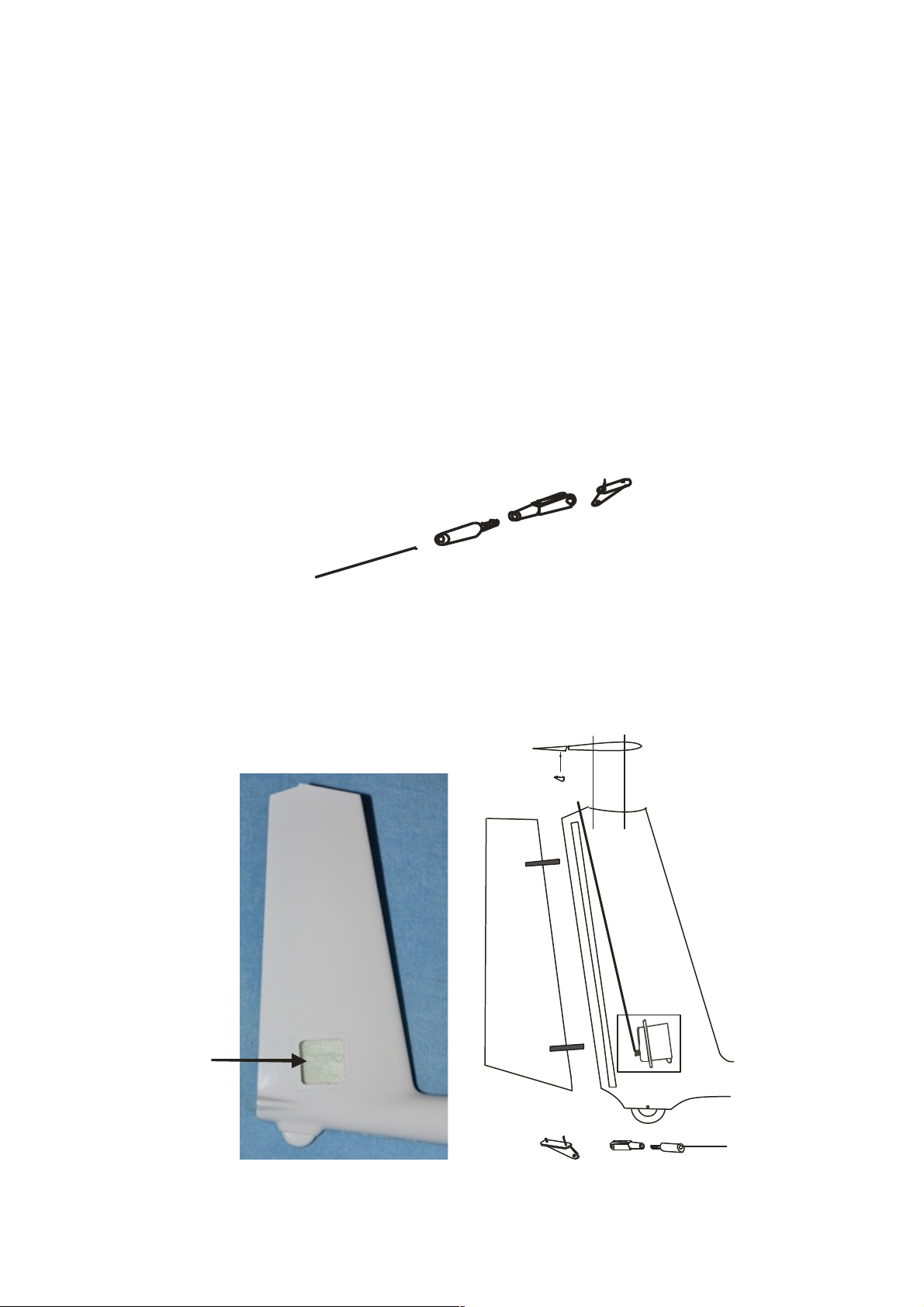
2. Rudder installation
The rudder is mounted on hinges. Make slots for hinges in both the stabilizer and the rudder - the
rudder must fit to the stabilizer. Glue the hinges into the stabilizer and then glue the rudder to the
hinges - mounting the rudder to the stabilizer this way. Find the position of the rudder control
horn so that the straight line connecting the holes in the horn and the axis of rotation of the
control surface is perpendicular to the surface of the stabilizer and the horn itself is in the same
level as the control wire coming from the fuselage. Drill two holes and fix the horn. Insert the
previously prepared wire into the bowden and connect it to the horn.
3. How to install the elevator servo
Drill the holes in the elevator with a diameter of 3mm for the screws. You must open the hole
for the servo in the vertical fin. It is advisable to use a small milling cutter.
Glue up the servo in the fin. Glue up the control lever on the elevator flap and join it using a
draw rod with the servo. Attach the cover.
4. Fitting the cockpit
open

Cut out the canopy transparent section using the mark line, glue it onto the epoxy frame, trim it
then and grind a bit off to a desirable shape.
The canopy is held in place with a pin and canopy lock. Bore then the matching holes in the
fuselage and in the canopy frame. Glue the pin in the front canopy frame. Glue the canopy lock
in the fuselage.
5. How to install the aileron servos
Install the extension servo cables into the wing. Connect the extension cables to the servos
(connectors or soldering -in this case isolate the wires using the heat shrinking tube). Attach the
control horns to the ailerons. Fix the ailerons in the neutral position using pieces of a self-
adhesive tape. Install single levers to the servos, adjust them to the neutral position and insert the
servos into the holders - without fixing them now. Prepare 2 rods made of 1mm diameter wire
with „Z“- bend on one end ,measure and cut the wires to the proper lengths and solder the brass
endings. Screw in the clevises. Remove the servos, insert the „Z“-bend into the servo lever, and
fix the servos in the holders using a quality double-side self adhesive tape or 5-min. epoxy.
Connect the pushrods to the control horns. Attach the servo covers using a double-sided self
adhesive tape.
6. How to install the servos to the brakes
Pin Lock

Attach the servos with two-sided Scotch tape to the channel and join them with the dive flap
using a draw rod. You will need extension cables and a Y-cable.
Shade your spoiler by pushing slightly with a small flat screwdriver on the arms of the bar (black
parts). Pull the Z of the manoeuvring on the gilded part and insert it into the interlocking hole
connecetd with the bottom of the servo. Shade again your spoiler and screw down your clevis at
the end of the manoeuvring. Demonstrate your servo heeding that the manoeuvring arm of the
servo is in the position of closed spoilers of your radion manoeuvring. (Example full gas on the
way of the engine manoeuvring of your radio) Adjust your manoeuvring and glue your servo
after having checked that both spoilers servos are moving in the right direction. Cover the servos
with the sheet.
7. Assembly of winglets
The winglest shall be glued to the wing ends. If it is necessary, chance the size of the gap in
order to insert winglet. Apply epoxy resin, insert winglet into the rib and leave it to get dry.
8. How to install the radio and batteries
Insert the batteries, power switch and receiver in the fuselage .Connect all the servos in the
fuselage with the radio. Use a Y-cable to connect the aileron servos to one channel only or use
two channels, if available, for ailerons. Use a Y-cable to flaps servos and brakes servos.
Use foam to protect them from vibrations and impacts. Connect all components as necessary.
9. Assembling and finishing the model
Glue the brass pipe for the wing coupling into the fuselage. The wing halves can be secured in
the right position either by self-adhesive tape or using a rubber ring. In this case make 1.8 mm
holes in the first wing ribs and screw in the hooks for the fixing rubber ring. Drill the holes in the
proper position in the fuselage for the rubber ring.
Applying the decorative stickers is the last step to finish your model.
glue
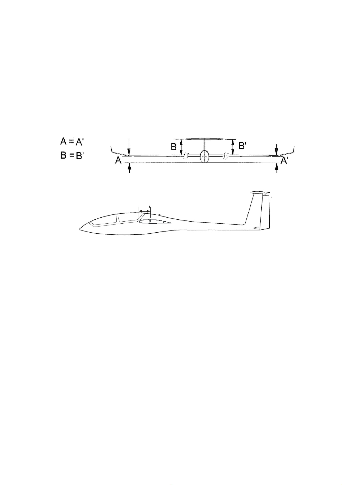
Balance: Check the centre of gravity position. This is a very important relationship between the CG
location and the stall characteristics of an airplane or knife-edge performance. CG location determines
the stall characteristics.
CG range from 27-30 mm measured from the leading edge at the root of the wing.
In workshop, ready to fly, carry the model on the fingers on each side of the fuselage at the wing
root, after having drawn the balance marks.
If the model leans forwards (nose heavy), move the battery backwards.
If the model leans backwards (tail heavy), move the battery forwards, add some lead if
necessary.
The plane is correctly balanced when it leans very slightly forwards with the index on the
reference marks.
FLYING
Insert the wing joiner into one wing, then into the fuse and add the other wing. The dowels
ensure the correct incidence of the wings. You can use a white or clear tape to attach the wings
to the fuse, only at upper side.
Don`t forget to check the symmetry of the whole model. Once on the field, first check the
function of your RC set and check the range, too. Calm wheather is the best for the first flights.
Try hand launching, trim if required for optimal gliding. Provided that everything is in order, you
can go for the maiden flight, with a charged battery of course.
Besides the slope soaring it is possible to install a tow hook and use a set for high-altitude
launches for thermal sparing.
Set up:
Rudder function: +/- 30 mm
Elevator function: +/- 6 mm
Aileron function: +8/-5 mm, term flight -1mm
Centre of Gravity - usually 27-30 mm from wing leading edge
Have a lot of fun and many happy landings with your DG-1001
CG 30 mm
Table of contents
Popular Toy manuals by other brands


Costway
Costway TQ10023 user manual

Fisher-Price
Fisher-Price wonder makers GFJ13 quick start guide

American Flyer
American Flyer 2-8-8-2 owner's manual

PLAYTIVE JUNIOR
PLAYTIVE JUNIOR 303642 Instructions for use

Oceanscience
Oceanscience Q-Boat 1800D user guide

GRAUPNER
GRAUPNER Junior Line Series instruction manual