DG TOE10G IP User manual

dg_toe10gip_cpu_instruction_xilinx_en.doc
23-Aug-19 Page 1
TOE10G IP with CPU Demo Instruction
Rev1.3 23-Aug-19
Contents
1Overview...............................................................................................................................2
Part ATOE10G IP with CPU demo by using FPGA and PC ........................................................3
2Environment Setup................................................................................................................3
3PC Setup...............................................................................................................................8
3.1 IP Setting........................................................................................................................8
3.2 Speed and Frame Setting...............................................................................................9
3.3 Power Option Setting....................................................................................................12
4FPGA board setup...............................................................................................................13
5Main menu ..........................................................................................................................19
5.1 Show TCPIP parameters..............................................................................................19
5.2 Reset TCPIP parameters..............................................................................................20
5.3 Send Data Test.............................................................................................................22
5.4 Receive Data Test.........................................................................................................25
5.5 Full duplex Test.............................................................................................................28
Part B TOE10G IP with CPU demo by using two FPGAs ..........................................................30
6Environment Setup..............................................................................................................30
7FPGA board setup...............................................................................................................32
8Main menu ..........................................................................................................................34
8.1 Display current parameter.............................................................................................34
8.2 Reset TCPIP parameters..............................................................................................35
8.3 Send Data Test (server to client)...................................................................................37
8.4 Receive Data Test (client to server)..............................................................................39
8.5 Full duplex Test.............................................................................................................41
9Revision History ..................................................................................................................43

dg_toe10gip_cpu_instruction_xilinx_en.doc
23-Aug-19 Page 2
1 Overview
The demo is designed to run TOE10G IP for transferring 10 Gb Ethernet data by using TCP/IP
protocol. Two test environments can be setup for the demo, as shown in Figure 1-1. First one
(Test Env#A) uses one FPGA board transferring data with Test PC. More details to run the demo
by using FPGA and Test PC are described in PartA. Second one (Test Env#B) uses two FPGA
boards to transfer data from the 1st FPGAto the 2nd FPGA. More details to run the demo by using
two FPGAs are described in PartB.
User interface for setting the test parameters on FPGA and monitoring the hardware status is
Serial console by using UART interface.
Figure 1-1 Two test environments for the demo

dg_toe10gip_cpu_instruction_xilinx_en.doc
23-Aug-19 Page 3
Part ATOE10G IP with CPU demo by using FPGAand PC
To transfer data between TOE10G IP and Test PC, user selects to run half-duplex or full-duplex
demo. “tcpdatatest” application is run on Test PC for half-duplex demo (sending data from
TOE10G IP to PC or receiving data from PC to TOE10G IP). “tcp_client_txrx_40G.exe”
application is run on Test PC for full-duplex demo (sending and receiving data with PC at the
same time). More details of the demo are described as follows.
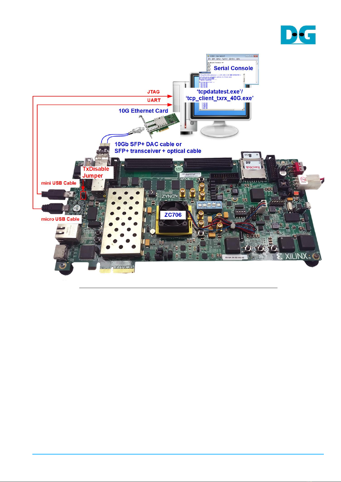
2 Environment Setup
To operate TOE10G IP with CPU demo, please prepare following test environment.
1) FPGA development boards (ZC706/ZCU102/KCU105/VCU118)
2) PC with 10 Gigabit Ethernet support or 10 Gigabit Ethernet card
3) 10 Gb SFP+ copper cable (DAC) or 2x10 Gb SFP+ transceiver (10G BASE-R) with optical
cable for network connection between FPGA board and PC
Note: For VCU118 board, QSFP+ to four SFP+ cable must be used for network
connection.
4) micro USB cable for programming FPGA, connecting between FPGA board and PC
5) mini USB cable (ZC706) or micro USB cable (ZCU102/KCU105/VCU118), connecting
between FPGAboard and PC for Serial console.
6) “tcpdatatest.exe” and “tcp_client_txrx_40G.exe” which are test application provided by
Design Gateway, installed on PC
7) Serial console software such as TeraTerm installed on PC. The setting on the console is
Baudrate=115,200, Data=8-bit, Non-parity, and Stop=1.
8) Vivado tool for programming FPGA, installed on PC
Note: Test result in this document is captured by using following test environment.
[1] 10G Network Adapter: Intel X520-DA2
http://www.intel.com/content/www/us/en/network-adapters/converged-network-adapters/
ethernet-x520-server-adapters-brief.html
[2] a) 10-Gigabit SFP+ DAC cable
http://www.netgear.com/business/products/switches/modules-accessories/axc761.aspx
b) 10-Gigabit SFP+ transceiver + optical cable
SFP+ transceiver (850nm)
http://www.fit-foxconn.com/Product/ProductDetail?topClassID=Electronic%20Module&&
PN=AFBR-709SMZ
Optical cable 2105027-3 (LC to LC 1.8mm OM3 DPX LSZH&OFNR 3M)
c) 40-Gigabit QSFP to 4x10-Gigabit SFP+ cable
https://www.finisar.com/active-optical-cables/fcbn510qe2cxx
[3] PC: Motherboard ASUS Z170-K, 32 GB RAM, and 64-bit Windows7 OS
dg_toe10gip_cpu_instruction_xilinx_en.doc
23-Aug-19 Page 4
Figure 2-1 TOE10G IP with CPU demo (FPGA <-> PC) on ZC706

dg_toe10gip_cpu_instruction_xilinx_en.doc
23-Aug-19 Page 5
Figure 2-2 TOE10G IP with CPU demo (FPGA <-> PC) on ZCU102

dg_toe10gip_cpu_instruction_xilinx_en.doc
23-Aug-19 Page 6
Figure 2-3 TOE10G IP with CPU demo (FPGA <-> PC) on KCU105

dg_toe10gip_cpu_instruction_xilinx_en.doc
23-Aug-19 Page 7
Figure 2-4 TOE10G IP with CPU demo (FPGA<-> PC) on VCU118
dg_toe10gip_cpu_instruction_xilinx_en.doc
23-Aug-19 Page 8
3 PC Setup
Before running demo, please check the network setting on PC. Following shows the example
of the network setting.
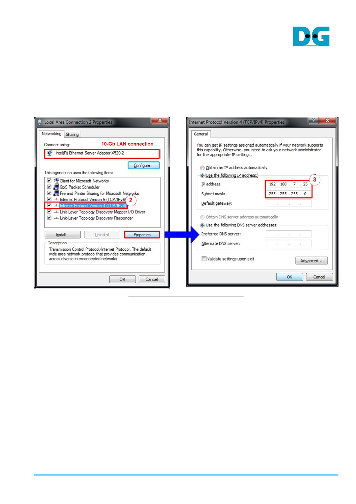
3.1 IP Setting
Figure 3-1 Setting IP address for PC
1) Open Local Area Connection Properties of 10-Gb connection, as shown in the left window
of Figure 3-1.
2) Select “TCP/IPv4” and then click Properties.
3) Set IP address = 192.168.7.25 and Subnet mask = 255.255.255.0, as shown in the right
window of Figure 3-1.
dg_toe10gip_cpu_instruction_xilinx_en.doc
23-Aug-19 Page 9
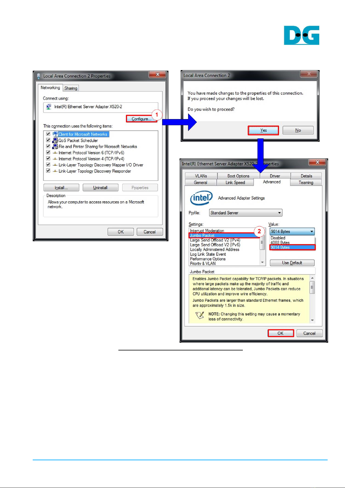
3.2 Speed and Frame Setting
Figure 3-2 Set frame size = jumbo frame
1) On Local Area Connection Properties window, click “Configure” as shown in Figure 3-2.
2) On Advanced Tab, select “Jumbo Packet”. Set Value to “9014 Bytes” for Jumbo Frame
support or set value to “Disabled” for non-Jumbo Frame support, as shown in the bottom
window of Figure 3-2.

dg_toe10gip_cpu_instruction_xilinx_en.doc
23-Aug-19 Page 11
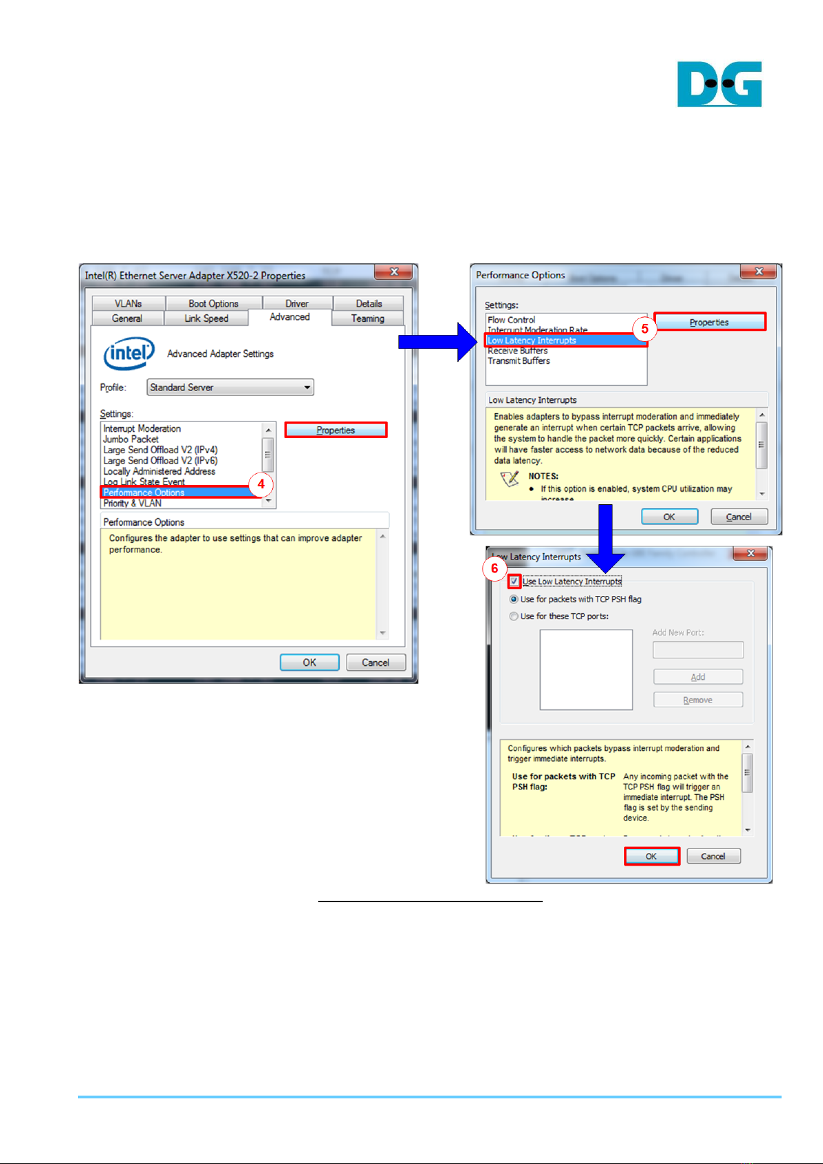
4) On Advanced Tab, select “Performance Options” and click “Properties” button.
5) On “Performance Options” window, select “Low Latency Interrupts” and click “Properties”
button.
6) On “Low Latency Interrupts” window, select “Use Low Latency Interrupts” and click “OK”
button.
7) Click “OK” button to save and exit all setting windows.
Figure 3-4 Performance option


dg_toe10gip_cpu_instruction_xilinx_en.doc
23-Aug-19 Page 13
4 FPGA board setup
1) Check DIPSW and jumper setting on FPGA board.
a) Board setting on ZC706 board is shown in Figure 4-1.
- Insert jumper to J17 to enable Tx SFP+
- Set SW11 to configure PS from JTAG
- Set SW4 to use USB-JTAG.
Figure 4-1 ZC706 board setting
b) Board setting on ZCU102 board is shown in Figure 4-2.
- Insert jumper to J16 to enable Tx SFP+
- Set SW6=all ONs to use USB-JTAG.
Figure 4-2 ZCU102 board setting

dg_toe10gip_cpu_instruction_xilinx_en.doc
23-Aug-19 Page 14
c) Board setting on KCU105 board is shown in Figure 4-3. Insert jumper to J6 to enable
Tx SFP+.
Figure 4-3 Insert jumper to enable SFP+ on KCU105
2) Connect micro USB cable from FPGA board to PC for JTAG programming.
3) Connect micro USB cable (ZCU102/KCU105/VCU118 board) or mini USB cable (ZC706
board) from FPGA board to PC for USB UART.
4) Connect power supply to FPGA development board.
5) Connect 10Gb Ethernet cable between FPGAboard and PC.
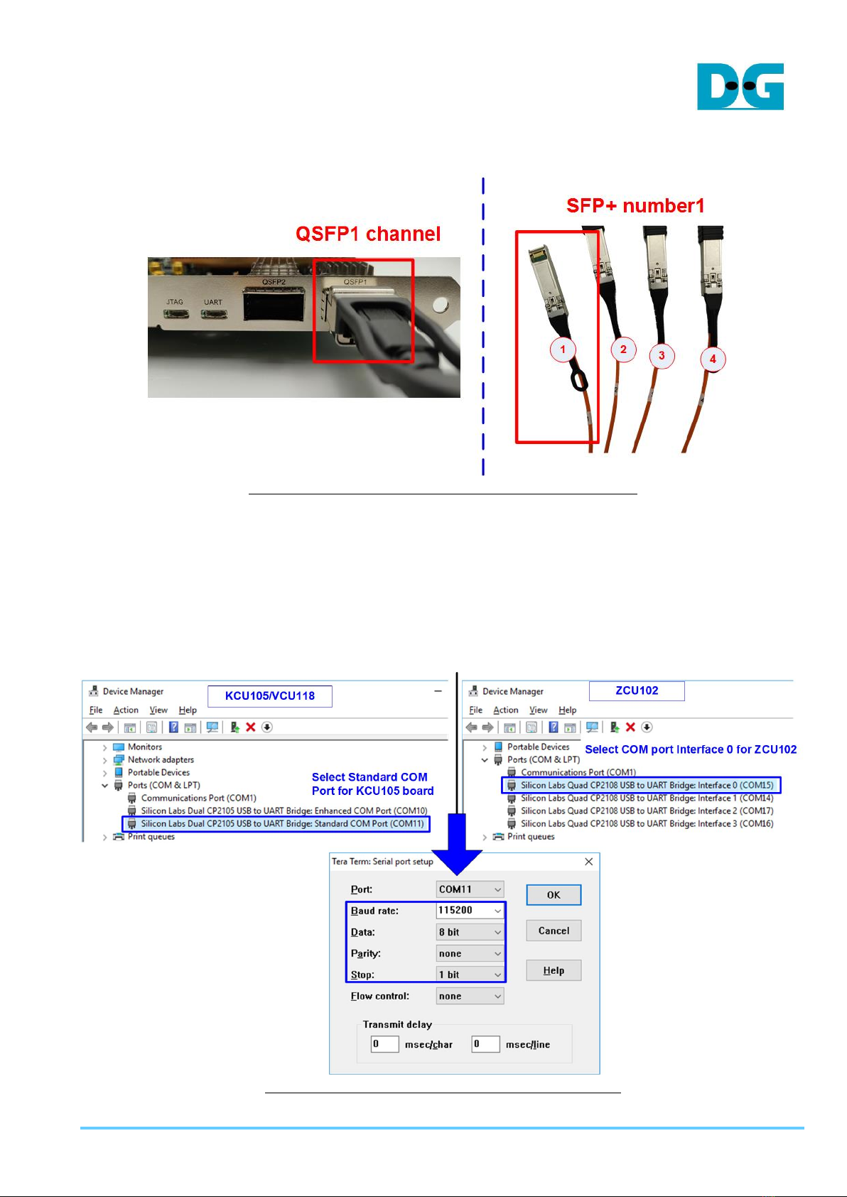
a) For ZCU102/KCU105/ZC706, insert 10-Gigabit SFP+ DAC or SFP+ transceiver with
optical cable. Some boards have many SFP connectors, use the channel as shown in
Figure 4-4.
Figure 4-4 SFP+ channel using on ZCU102/KCU105 board
dg_toe10gip_cpu_instruction_xilinx_en.doc
23-Aug-19 Page 15
b) For VCU118, insert QSFP+ to 4 SFP+ cable between FPGAboard and PC. Use SFP+
no.1 to connect to FPGA as shown in Figure 4-5
Figure 4-5 QSFP+ channel using on VCU118 board
6) Power on FPGA board.
7) Open Serial console. When connecting FPGA board to PC, many COM ports from FPGA
connection are detected and displayed on Device Manager.
In case of KCU105/VCU118, select Standard COM port.
In case of ZCU102, select COM port number of Interface0 (COM15 in the right side of
Figure 4-6) for Serial console.
On Serial console, use following setting: Buad rate=115,200, Data=8-bit, Non-Parity, and
Stop = 1.
Figure 4-6 COM port number for Serial console
dg_toe10gip_cpu_instruction_xilinx_en.doc
23-Aug-19 Page 16
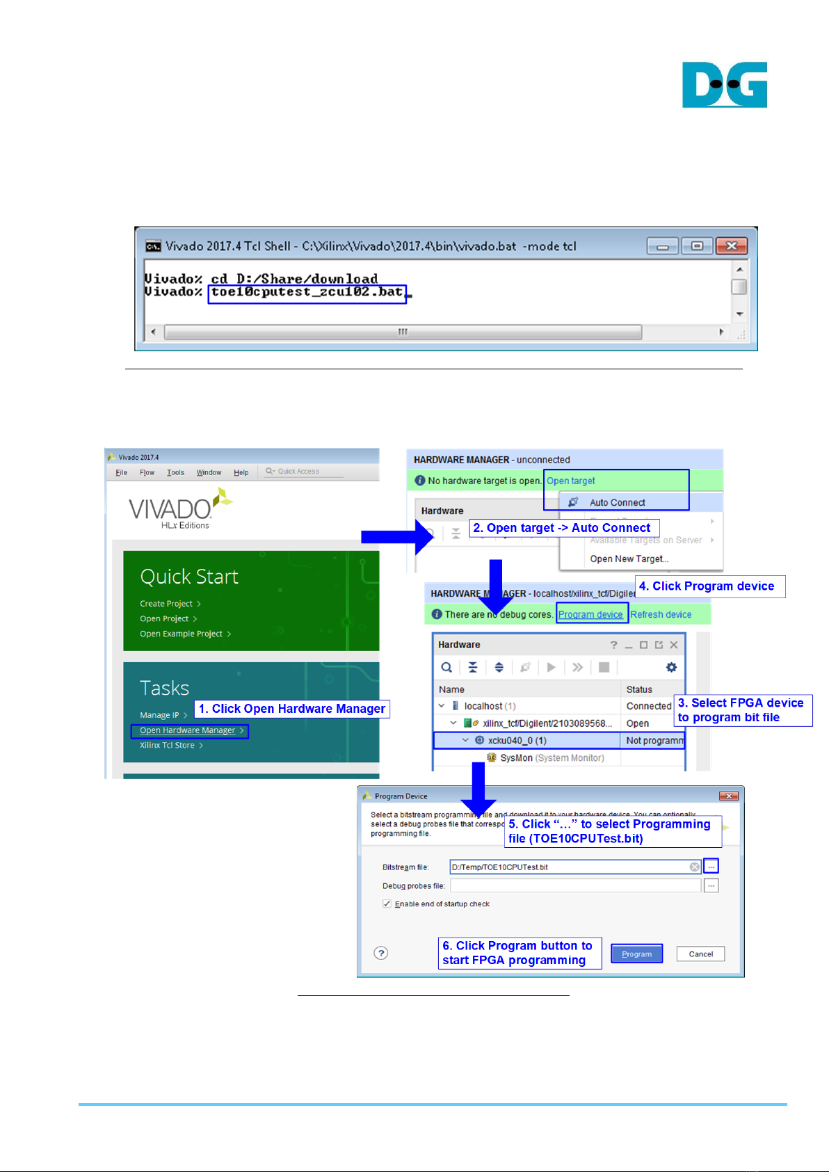
8) Download configuration file and firmware to FPGA board
a) For ZCU102/ZC706 board, open Vivado TCL shell and change current directory to
download folder which includes demo configuration file. Type “toe10cputest_zcu102
(or zc706).bat, as shown in Figure 4-7.
Figure 4-7 Example command script for download to ZC706/ZCU102 by Vivado tool
b) For KCU105 board, use Vivado tool to program configuration file, as shown in Figure
4-8
Figure 4-8 Program FPGA by Vivado

dg_toe10gip_cpu_instruction_xilinx_en.doc
23-Aug-19 Page 17
9) Input ‘0’ to initialize TOE10G IP in client mode (ask PC MAC address by sending ARP
request).
10)Default parameter in client mode is displayed on the console.
Figure 4-9 Message after system boot-up
If Ethernet connection has the problem and the status is linked down, the error message
will be displayed on the console instead of welcome message, as shown in Figure 4-10.
Figure 4-10 Error message when cable is linked down

dg_toe10gip_cpu_instruction_xilinx_en.doc
23-Aug-19 Page 18
11)User inputs ‘x’ to skip parameter setting for using default parameters to initialize system,
as shown in Figure 4-11. If user inputs other keys, the menu to change parameter will be
displayed. The example to change parameter is shown in topic 5.2 (Reset TCPIP
parameters).
Figure 4-11 Initialization complete
Note: Transfer performance in the demo depends on Test PC resource in Test platform.

dg_toe10gip_cpu_instruction_xilinx_en.doc
23-Aug-19 Page 19
5 Main menu
5.1 Show TCPIP parameters
Select ‘0’ to check current parameter in the demo. There are seven parameters displayed on
the console.
Figure 5-1 Display current parameter result
1) Window Update Gap: Set threshold value to transmit window update packet. Valid value
is 0x00 –0x3F (0-63). The unit size of threshold value is 1 Kbyte. Default value is 0
(disable window update feature).
2) Mode: Set mode to TOE10G IP to act as server or client. To run with PC, please input ‘0’
to initialize the IP in client mode.
3) FPGA MAC address: 48-bit hex value to be MAC address of FPGA. Default value is
0x000102030405.
4) Target IP: IP address of destination device (10 Gb Ethernet on PC). Default value is
192.168.7.25.
5) FPGA IP: IP address of FPGA. Default value is 192.168.7.42.
Note: This value is used to be server IP address, the input parameter of test application
on PC.
6) Target port number: Port number of destination device to transfer 10 Gb Ethernet data.
Default value is 60001.
7) FPGA port number: Port number of FPGA. Default value is 60000.
Note: This value is used to be server port, the input parameter of test application on PC.
To change some parameters, user can set by using menu [1].

dg_toe10gip_cpu_instruction_xilinx_en.doc
23-Aug-19 Page 20
5.2 Reset TCPIP parameters
Select ‘1’ to reset the IP and change IP parameters.
This menu is used to change IP parameters or send reset to TOE10 IP. After user selects
this menu, the current parameters are displayed on the console. User enters ‘x’ to use same
parameters while other keys are entered to change some parameters. After the parameters
are fixed, reset signal is sent to TOE10G IP.
There are seven parameters to set in this menu. Each parameter is verified by CPU. The
parameter is updated to TOE10G IP when the input is valid. If the input is not valid, the
parameter will not change. After user inputs all parameters, IP is reset. The description of
each parameter is shown in topic 5.1(Show TCPIP parameters) and the range of each
parameter is described as follows.
1) Window Update Gap: Set threshold value to transmit window update packet. Valid value
is 0x00 –0x3F (0-63). The unit size of threshold value is 1 Kbyte. Default value is 0
(disable window update feature).
2) Mode: Input ‘0’ to initialize the IP as client mode.
3) FPGAMAC address: Input 12 digit of hex value. Add “0x” as a prefix to input as hex value.
4) FPGA IP address: A set of four decimal digits is separated by “.”. The valid range of each
decimal number is 0-255.
5) FPGA port number: Valid range is 0-65535.
6) Target IP address: A set of four decimal digits like FPGA IP address. This value is IP
address of Test PC.
7) Target port number: Valid range is 0-65535.
After finishing parameter assignment, new parameters set is displayed on the console. Next,
reset signal is sent to the IP to use new parameters set. Finally, “IP initialization complete” is
shown after IP completes initialization process, as shown in Figure 5-2.
Table of contents
Other DG Motherboard manuals


