DGH MS 2000 User manual
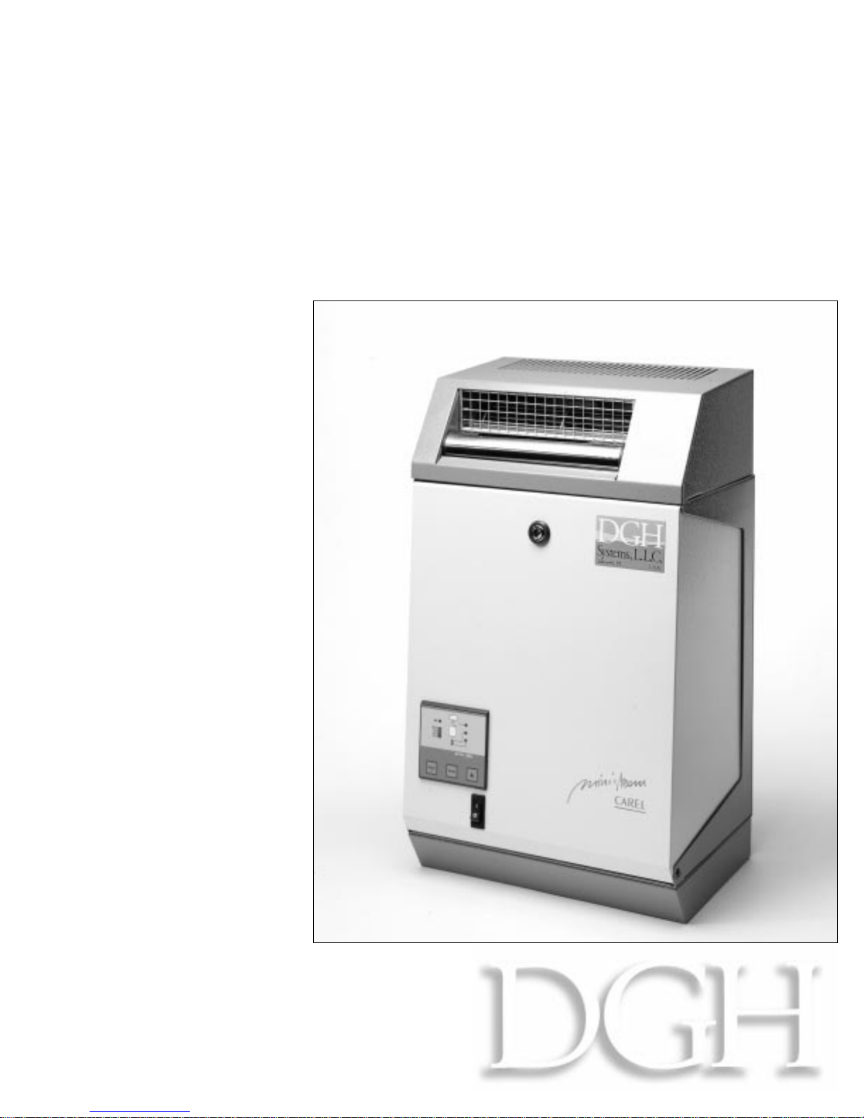
MS2000
Electronic Steam
Humidifiers
MiniSteam
Residential
Owner’s
Manual
Read and Save
these Instructions

Systems, L.L.C.
Item Page
CONTENTS
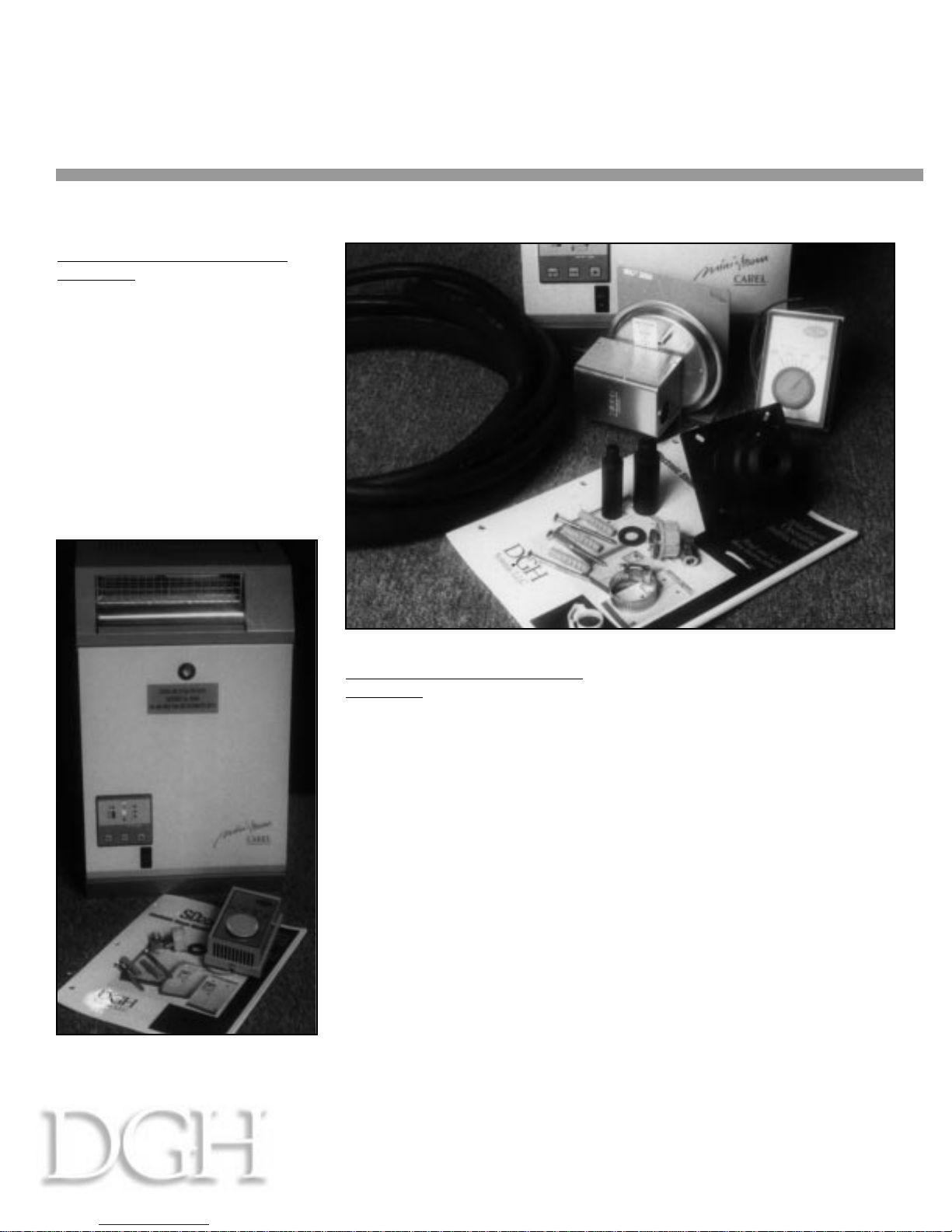
Your MiniSteam steam humidifier will consist of:
INSTALLATION
MOUNTING THE HUMIDIFIER
MOUNTING THE STEAM NOZZLE
RUNNING THE STEAM HOSE.
PLUMBING
POWER WIRING
CONTROL WIRING
START UP AND CHECK OUT OF THE SD 2000 HUMIDIFIER
Startup Checklist
Startup Procedures
OPERATING YOUR MINISTEAM HUMIDIFIER
The MiniSteam Controller
The Main Control Board
MAINTENANCE
Cleaning the steam cylinder
Cleaning the fill and drain valves
ALARMS & FAULT CONDITIONS
Other Trouble-Shooting Hints
REPLACEMENT PARTS - BLOWER UNIT
REPLACEMENT PARTS - HUMIDIFIER UNIT
HUMIDIFIER WIRING DIAGRAM
TECHNICAL SPECIFICATIONS
1
2
2
6
7
9
10
11
13
13
13
14
15
16
17
17
18
19
21
21
21
22
23
Limited Warranty
All Products manufactured by DGH Systems, L.L.C. are warranted to the original purchaser to be free
from defects in materials and workmanship in the course of normal and reasonable use for a period of 2
years from the date of installation or 2 years and 1 month from the date of shipment, whichever comes first,
so long as the product has been installed and operated in accordance with all appropriate manuals and
wiring diagrams.
Any product or part that is found to be defective will, at the option of DGH Systems, L.L.C. be
replaced or repaired. DGH Systems, L.L.C. reserves the right to inspect any part or installation before
replacing or repairing defective parts. After startup of the product, labor for repairs or replacement of parts is
not covered by this warranty. Replacement of routinely replaceable parts such steam cylinders and gaskets
are not covered by this warranty.
DGH Systems, L.L.C. assumes no liability for consequential or inconsequential damage, or damage
due to negligence or improper use. Under the terms of this warranty, the original purchaser may have certain
legal rights and other rights which may vary from state to state.
1
Systems, L.L.C.
MS2000
MiniSteam Residential
Owner’s Manual
For duct mounted applications
(Figure 1):
■1 Steam humidifier unit
■1 Duct steam nozzle
■10’ - 7/8” ID steam hose
■2 Steam hose clamps
■10’ - 5/16” ID condensate hose
■1 Condensate hose clamp
■1 HC-101 humidistat
■1 PC-301 air proving switch
■2 Fill cup extenders
■3 Screws and anchors
■1 Fill connector
For room mounted applications
(Figure 2):
■1 Steam humidifier unit with
blower attached
■1 HC-101 humidistat
■3 Screws and anchors
■1 Fill connector
IMPORTANT:
BEFORE beginning
installation:
■Check for shipping damage to
cartons. Mark the shipping waybill
accordingly.
■Open cartons and check for any
hidden damage. Mark the shipping
waybill accordingly.
■Check packing slip to insure all
items have been received. Notify
DGH immediately of any
shortages or damaged parts.
You
must notify DGH within 5
working days of any shortages.
2
Your
MiniSteam
steam humidifier will consist of:
Figure 1
Figure 2

Systems, L.L.C.
MS2000
MiniSteam Residential
Owner’s Manual
1. Open the carton and carefully
remove the humidifier and
accessories.
2. Open the humidifier, using a flat
blade screwdriver, and remove the
mounting hardware and
accessories.
3. Remove the plastic steam
cylinder by loosening the clamp
on the top left of the cylinder and
lifting the cylinder while twisting it
up out of its base.
a. Disconnect the wires on
top by carefully loosening and
removing the plastic knobs
holding them in place.
Carefully use a pliers if
necessary to loosen the knobs.
CAUTION:
Do not squeeze
the pliers too hard, and turn
counter-clockwise only.
3
Installation - Mounting the Humidifier
Figure 3
Systems, L.L.C.
MS2000
MiniSteam Residential
Owner’s Manual
4
4. Locate where you will install
the duct steam nozzle in the duct
(if used), and then decide on a
convenient location for the
humidifier, that will permit the
hoses to be sloped properly.
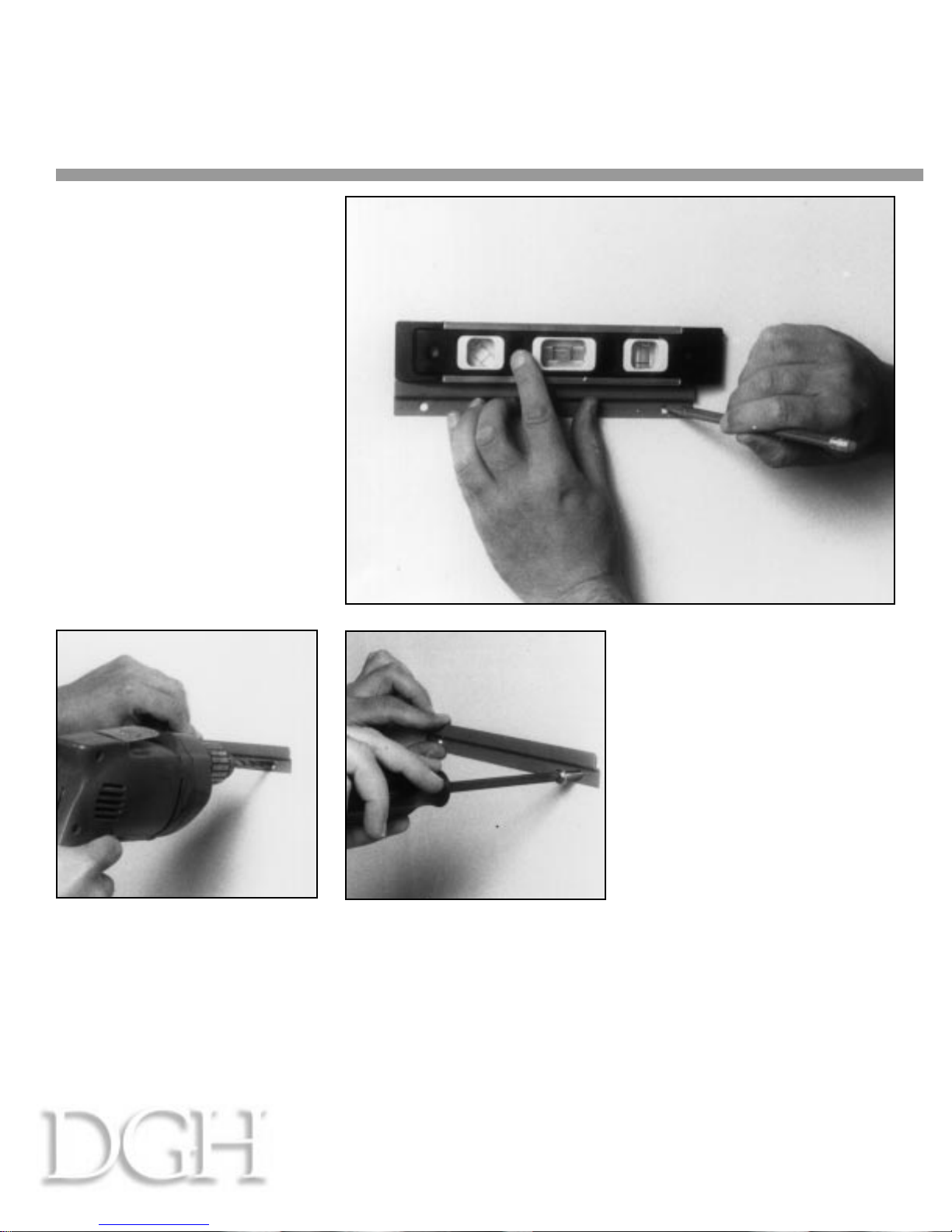
5. Use the mounting bracket to
mark the wall for drilling. Use a
level to insure the unit will hang
level. (See Figure 4 at right)
CAUTION:
make sure that the
screws will go into wall studs to
support the weight of the
humidifier.
6. If the mounting screws will be
screwed into wood, drill 2 -1/8"
pilot holes for the mounting
bracket. If dry wall, drill 2 -5/16"
holes for the anchors.
(See Figure 5 above)
7. Insert the screw anchors if
needed and then screw in the
mounting screws through the
bracket. The top edge of the
bracket should stand out away
from the wall.
(See Figure 6 above)
Figure 4
Figure 6
Figure 5

Systems, L.L.C.
MS2000
MiniSteam Residential
Owner’s Manual
DIMENSIONS:
A=Clearance in front of
humidifier 36" (72" with blower)
B=Clearance to left side of
humidifier 12"
C=Clearance to right side of
humidifier 12"
D=Clearance to right side of
blower unit 12"
E=Clearance from top of blower
to ceiling 24"
F=Clearance from bottom of
humidifier to floor 12"
IMPORTANT:
Maximum length of
rubber steam hose is 20 feet.
10 feet is supplied with the
humidifier.
5
9. Remove the mounting bracket
from the back of the humidifier
Mount the humidifier unit as close
to the steam distributor pipe as
possible to minimize condensate.
Mount the humidifier unit below
the steam distributor pipe
whenever possible. Insure that a
slope can be maintained in the
steam hoses. Certain mounting
clearances must be maintained to
allow access for maintenance, and
for steam discharge from the
blower unit:
Figure 8
Figure 7

6
Systems, L.L.C.
MS2000
MiniSteam Residential
Owner’s Manual
10. Hang the humidifier unit
carefully on the mounting bracket.
(See Figure 9 at right)
11. Secure the bottom of the
humidifier unit to the wall using
the third screw.
(See Figure 10 at right)
Figure 9
Figure 10

Systems, L.L.C.
MS2000
MiniSteam Residential
Owner’s Manual
12. Locate a suitable position for
the steam nozzle per Figure 11
at right.
a. Locate the nozzle at least
18" upstream of any duct
takeoffs or elbows.
b. If the steam nozzle is
installed from the bottom of
the duct, locate it in the center,
and cap off the condensate
outlet nipple.
12. Cut or drill a 2-1/2" hole in the
side of the duct to fit the steam
nozzle.
13. Apply silicone caulk to the
faceplate of the steam nozzle and
insert it into the duct with the 5/16"
outlet nipple at the bottom, as
shown in Figure 12 above.
14. Attach the steam nozzle to the
duct using #10 by 1/2" drill point
sheet metal screws (not included).
Be sure the nozzle is mounted
level, with the 5/16" outlet nipple at
the bottom.
(See Figure 13 above)
Installation - Mounting the Steam Nozzle
Figure 12
Figure 11 Figure 13
7

8
Systems, L.L.C.
MS2000
MiniSteam Residential
Owner’s Manual
CAUTION:
90% of all
operational problems with the
MiniSteam humidifier can be
traced to improper installation of
the steam hose. It is very critical
that steam be allowed to flow
freely from the humidifier unit to
the steam nozzle, and that
condensate can flow back.
■A 20% slope must be
maintained from the humidifier
unit to the steam nozzle. That
means the hose must slope up
2 1/2" for every foot of the
length of the steam hose.
■There must be NO sags,
kinks or low areas in the steam
hose that can collect
condensate or otherwise
restrict the steam flow.
■Copper tubing may be used
in place of the steam hose, but
it must be a minimum of 7/8"
ID and must be insulated.
DO NOT REDUCE THE SIZE
OF THE STEAM HOSE OR
PIPE.
16. Slip the end of the 7/8" ID
rubber steam hose over steam
nozzle inlet nipple and secure it
with the stainless steel hose clamp
supplied.
(See Figure 15 at right)
17. Slip the 5/16" ID condensate
hose over the steam nozzle
condensate outlet nipple and
secure it with the plastic hose
clamp supplied.
(See Figure 16 at right)
Installation - Running the Steam Hose
Figure 14
Figure 15
Figure 16
Systems, L.L.C.
MS2000
MiniSteam Residential
Owner’s Manual
9
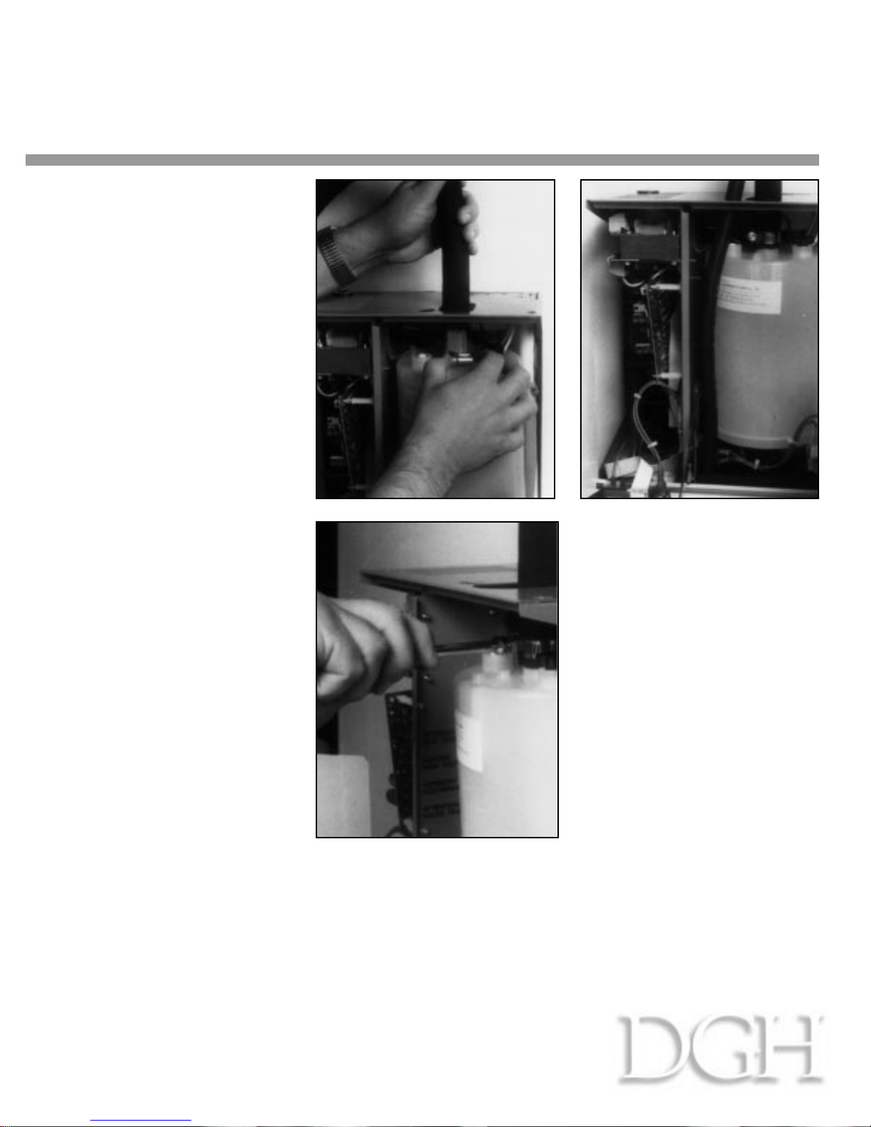
18. Bring the end of the steam
hose through the hole in the top of
the humidifier cabinet and slip the
end over the steam cylinder outlet.
Secure the hose using the stainless
the steel hose clamp supplied.
(See Figure 17 at right)
18. Reinstall the steam cylinder
into the humidifier unit by pressing
it down into the O-ring fitting at
the bottom, and then securing all
wires.
CAUTION:
Loose electrical
connections could cause fire, so
make sure all fittings are tight.
(See Figure 18 above)
20. Bring the end of the
condensate hose through the
smaller hole in the top of the
humidifier cabinet and cut it so it
ends in the drain pan of the
humidifier.
(See Figure 19 above)
Figure 17
Figure 18
Figure 19
This manual suits for next models
1
Table of contents


